HA-H18R410INV3 - Aircondition Alhafidh - Gratis brugsanvisning og manual
Find enhedens vejledning gratis HA-H18R410INV3 Alhafidh i PDF-format.

Brugerspørgsmål om HA-H18R410INV3 Alhafidh
0 spørgsmål om dette apparat. Besvar dem du kender, eller stil dit eget.
Stil et nyt spørgsmål om dette apparat
Download vejledningen til din Aircondition i PDF-format gratis! Find din vejledning HA-H18R410INV3 - Alhafidh og tag din elektroniske enhed tilbage i hånden. På denne side er alle dokumenter nødvendige for brugen af din enhed offentliggjort. HA-H18R410INV3 af mærket Alhafidh.
BRUGSANVISNING HA-H18R410INV3 Alhafidh


أجهزة التبريد نوع سبلت
دليل المستخدم
الموديل:
HA-H18R410INV3 ▲
HA-H26R410INV3
Split Type AIR CONDITIONERS
User's Manual
Model:
▲ HA-H18R410INV3 HA-H26R410INV3
الرجاء قراعة هذا الدليل بعتناية قبل تشغيل الجهاز، و احتفظ به لLRجوع Elizabeth مستقبلا.
هذه التصاميم و المواصفات عرضة للënغير بهدف إدخال تحسينات عليها و ذلك دون إشعار سبQC.
ISO9001 CB
Please read this manual carefully before operating your set. Retain it for future reference.
Designs and specifications are subject to change for improvement without prior notice.
ISO9001 CB


Table of Contents
SAFETY PRERCAUTIONS 1
NAMES OF PARTS 4
INDOOR UNIT DISPLAY 5
EMERGENCY FUNCTION & AUTO-RESTART FUNCTION 6
REMOTE CONTROLLER 7
OPERATING INSTRUCTIONS....11
PROTECTION 17
INSTALLATION MANUAL....18
MAINTENANCE 27
TROUBLE SHOOTING 28
In line with the company's policy of continual product improvement, the aesthetic and dimensional characteristics, technical data and accessories of this appliance may be changed without notice.
SAFETY RULES AND RECOMMENDATIONS FOR THE INSTALLER
Read this guide before installing and using the appliance.
During the installation of the indoor and outdoor units the access to the working area should be forbidden to children. Unforesecable accidents could happen.
⚠ Make sure that the base of the outdoor unit is firmly fixed.
⚠️ Check that air cannot enter the refrigerant system and check for refrigerant leaks when moving the air conditioner.
⚠️ Carry out a test cycle after installing the air conditioner and record the operating data.
The user must protect the indoor unit with a fuse of suitable capacity for the maximum input current or with another overload protection device.
⚠ Ensure that the mains voltage corresponds to that stamped on the rating plate. Keep the switch or power plug clean. Insert the power plug correctly and firmly into the socket, thereby avoiding the risk of electric shock or fire due to insufficient contact.
⚠️ Check that the socket is suitable for the plug, otherwise have the socket changed.
The appliance must be fitted with means for disconnection from the supply mains having a contact separation in all poles that provide full disconnection under overvoltage category III conditions, and these means must be incorporated in the fixed wiring in accordance with the wiring rules.
The air conditioner must be installed by professional or qualified persons.
Do not install the appliance at a distance of less than 50 cm from inflammable substances (alcohol, etc.) Or from pressurised containers (e.g. spray cans).
If the appliance is used in areas without the possibility of ventilation, precautions must be taken to prevent any leaks of refrigerant gas from remaining in the environment and creating a danger of fire
The packaging materials are recyclable and should be disposed of in the separate waste bins. Take the air conditioner at the end of its useful life to a special waste collection centre for disposal.
Only use the air conditioner as instructed in this booklet. These instructions are not intended to cover every possible condition and situation. As with any electrical household appliance, common sense and caution are therefore always recommended for installation, operation and maintenance.
The appliance must be installed in accordance with applicable national regulations.
⚠ Before accessing the terminals, all the power circuits must be disconnected from the power supply.
The appliance shall be installed in accordance with national wiring regulations.
This appliance can be used by children aged from 8 years and above and persons with reduced physical, sensory or mental capabilities or lack of experience and knowledge if they have been given supervision or instruction concerning use of the appliance in a safe way and understand the hazards involved. Children shall not play with the appliance. Cleaning and user maintenance shall not be made by children without supervision.
SAFETY RULES AND RECOMMENDATIONS FOR THE USER
Do not try to install the conditioner alone; always contact specialized technical personnel.
△ Cleaning and maintenance must be carried out by specialised technical personnel. In any case disconnect the appliance from the mains electricity supply before carrying out any cleaning or maintenance.
⚠ Ensure that the mains voltage corresponds to that stamped on the rating plate. Keep the switch or power plug clean. Insert the power plug correctly and firmly into the socket, thereby avoiding the risk of electric shock or fire due to insufficient contact.
Do not pull out the plug to switch off the appliance when it is in operation, since this could create a spark and cause a fire, etc.
This appliance has been made for air conditioning domestic environments and must not be used for any other purpose, such as for drying clothes, cooling food, etc.
The packaging materials are recyclable and should be disposed of in the sparate waste bins. Take the air conditioner at the end of its useful life to a special waste collection centre for disposal.
Always use the appliance with the air filter mounted. The use of the conditioner without air filter could cause an excessive accumulation of dust or waste on the inner parts of the device with possible subsequent failures.
The user is responsible for having the appliance installed by a qualified technician, who must check that it is earthed in accordance with current legislation and insert a thermomagnetic circuit breaker.
The batteries in remote controller must be recycled or disposed of properly. Disposal of Scrap Batteries --- Please discard the batteries as sorted municipal waste at the accessible collection point.
△ Never remain directly exposed to the flow of cold air for a long time. The direct and prolonged exposition to cold air could be dangerous for your health. Particular care should be taken in the rooms where there are children, old or sick people.
⚠️ If the appliance gives off smoke or there is a smell of burning, immediately cut off the power supply and contact the Service Centre.
The prolonged use of the device in such conditions could cause fire or electrocution.
Have repairs carried out only by an authorised Service Centre of the manufacturer. Incorrect repair could expose the user to the risk of electric shock, etc.
⚠ Unhook the automatic switch if you foresee not to use the device for a long time.
The airflow direction must be properly adjusted
The flaps must be directed downwards in the heating mode and upwards in the cooling mode.
Only use the air conditioner as instructed in this booklet. These instructions are not intended to cover every possible condition and situation. As with any electrical household appliance, common sense and caution are therefore always recommended for installation, operation and maintenance.
⚠ Ensure that the appliance is disconnected from the power supply when it will remain inoperative for a long period and before carrying out any cleaning or maintenance.
Selecting the most suitable temperature can prevent damage to the appliance.
SAFETY RULES AND PROHIBITIONS
Do not bend, tug or compress the power cord since this could damage it. Electrical shocks or fire are probably due to a damaged power cord. Specialised technical personnel only must replace a damaged power cord.
Do not use extensions or gang modules.
Do not touch the appliance when barefoot or parts of the body are wet or damp.
Do not obstruct the air inlet or outlet of the indoor or the outdoor unit.
The obstruction of these openings causes a reduction in the operative efficiency of the conditioner with possible consequent failures or damages.
In no way alter the characteristics of the appliance.
Do not install the appliance in environments where the air could contain gas, oil or sulphur or near sources of heat.
This appliance is not intended for use by persons (including children) with reduced physical, sensory or mental capabilities, or lack of experience and knowledge, unless they have been given supervision or instruction concerning use of the appliance by a person responsible for their safety.
Do not climb onto or place any heavy or hot objects on top of the appliance.
Do not leave windows or doors open for long when the air conditioner is operating.
Do not direct the airflow onto plants or animals.
A long direct exposition to the flow of cold air of the conditioner could have negative effects on plants and animals.
Do not put the conditioner in contact with water.
The electrical insulation could be damaged and thus causing electrocution.
Do not climb onto or place any objects on the outdoor unit
Never insert a stick or similar object into the appliance. It could cause injury.
Children should be supervised to ensure that they do not play with the appliance. If the supply cord is damaged, it must be replaced by the manufacturer, its service agent or similarly qualified persons in order to avoid a hazard.
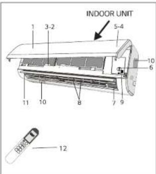
NAMES OF PARTS
INDOOR UNIT
| No. | Description |
| 1 | Front panel |
| 2 | Air filter |
| 3 | Optional filter (if installed) |
| 4 | LED Display |
| 5 | Signal receiver |
| 6 | Terminal block cover |
| 7 | Ionizer generator(if installed) |
| 8 | Deflectors |
| 9 | Emergency button |
| 10 | Indoor unit rating label (Stick position optional) |
| 11 | Airflow direction louver |
| 12 | Remote controller |
OUTDOOR UNIT
| No. | Description |
| 13 | Air outlet grill |
| 14 | Outdoor unit rating label |
| 15 | Terminal block cover |
| 16 | gas valve |
| 17 | liquid valve |
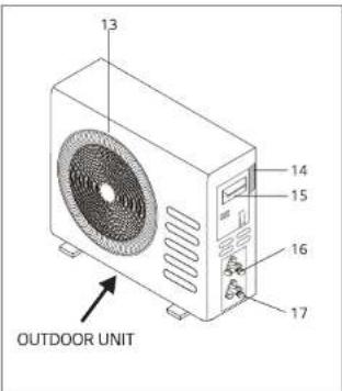
Note: the above figures are only intended to be a simple diagram of the appliance and may not correspond to the appearance of the units that have been purchased.
INDOOR UNIT DISPLAY
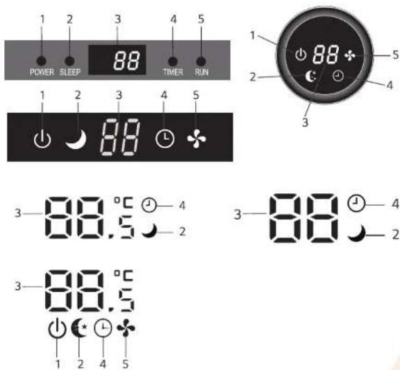
| No. | Led | Function | |
| 1 | POWER | ➊ | This symbol appears when the unit is power on |
| 2 | SLEEP | ➒ | SLEEP mode |
| 3 | Temperature display (if present) /Error code | 88 | (1) Lights up during Timer operation when the air conditioner is operational(2) Displays the malfunction code when fault occurs. |
| 4 | TIMER | ➉ | Lights up during Timer operation. |
| 5 | RUN | ♣ | The symbol appears when the unit is turned on, and disappear when the unit is turned off |
The shape and position of switches and indicators may be different according to the model, but their function is the same.
According to the model, it may only show 2 numbers on the indoor display though there are 3 numbers on display of the remote controller. (Example: It is 28 in the display of the remote controller but 28 on the indoor display)
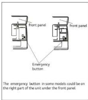
EMERGENCY FUNCTION & AUTO RESTART FUNCTION
EMERGENCY FUNCTION
If the remote controller fails to work or maintenance necessary, proceed as follows:
Open and lift the front panel up to an angleto reach the emergency button.
1. One press of the emergency button(one beep) will lead to the forced COOLING operation
2. Two press of the emergency button within 3 sec (two beeps) will lead to the forced HEATING operation.
3. To switch off the unit, you just need to press the button again (a single long beep).
4. After 30 minutes in forced operation, the air conditioner will automatically start working in 23°C cooling mode, auto fan speed.
5. The AUTO function is described in page 13.
AUTO-RESTART FUNCTION
The appliance is preset auto - restart function by manufacturer. In case of a sudden power failure, the module memorizes the setting conditions before the power failure. when the power restores, the unit restarts automatically with all the previous settings preserved by the memory function.

The shape and position of the emergency button may be different according to the model, but their function is the same.
Remark: the external static pressure of heat pumps is 0 Pa for all models.
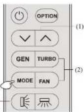
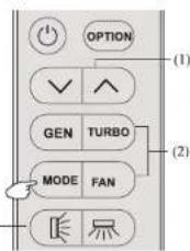
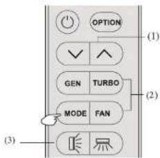
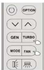
REMOTE CONTROLLER
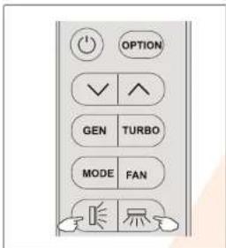
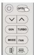
| No. | Button | Function |
| 1 | To turn on or off the air conditioner | |
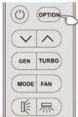
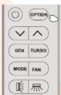
| 2 | OPTION | To activate or deactivate optional function(Check below table) |
| 3 | To decrease temperature, time setting or choose the function | |
| 4 | To increase temperature, time setting or choose the function. | |
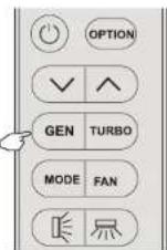
| 5 | GEN | To activate/deactivate the GEN function which enables the unit run in the set current level,cycle as below OFF→L3→L2→L1" |
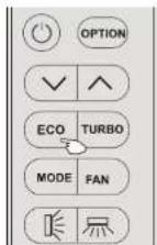
| ECO | Press this button to activate/deactivate the ECO function. | |
| 6 | TURBO | Press this button to activate/deactivate the Super function which enables the unit to reach the preset temperature in the shortest time. |
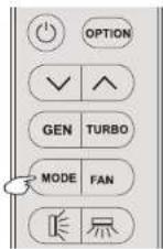
| 7 | MODE | To select the mode of operation(AUTO COOL DR Y FAN HEA T) |
| 8 | FAN | To select the fan speed of auto/mute/low/mid-low/mid/mid-high/high/turbo, cycle as below. _tave |
| 9 | To activate the swing of horizontal flap(up/down) or deactivate it. | |
| 10 | To activate the swing of vertical flap(left/right) or deactivate it. |
| ON/OFF | Mode | OPTIONS |
| ON | AUTO | TIMER DISPLAY HEALTH IFEEL 8°C H |
| COOL | TIMER DISPLAY HEALTH SLEEP MILDEWI FEEL 8°C H | |
| DRY | TIMER DISPLAY HEALTH MILDEWI FEEL 8°C H | |
| FAN | TIMER DISPLAY HEALTH IFEEL 8°C H | |
| HEAT | TIMER DISPLAY HEALTH SLEEP I FEEL 8°C H | |
| OFF | AUTO | CLEAN TIMER DISPLAY HEALTHI FEEL 8°C H |
| COOL | CLEANEAN TIMER DISPLAY HEALTH SLEEP MILDEWI FEEL 8°C H | |
| DRY | CLEAN TIMER DISPLAY HEALTH MILDEWI FEEL 8°C H | |
| FAN | CLEAN TIMER DISPLAY HEALTHI FEEL 8°C H | |
| HEAT | CLEAN TIMER DISPLAY HEALTH SLEEP I FEEL 8°C H |
You will hear a beep when you press the following buttons or select the following optional functions, though the actual model haven't this function, we express our apologies:
(Optional Function: COMFORTABLE COOLING airflow)
HEALTH (Optional Function generate the ionizer)
(Optional Function: COMFORTABLE HEATING airflow)
(button: SWING LEFT/RIGHT)
[BCH] (Optional Functions 8°C Heating)
(Optional Function: Wide-angle air supply)
© Alhafidh Group Trading fzco. 2019
Reproduction in whole or in part is strictly prohibited
REMOTE CONTROLLER
![AUTO COOL, DRY MAX. MAX. DRY 0.0 °C + + all SIN (EMEA) [Pm] DIN: DIN: DIN: DIN [EMEA] [EMEA] [EMEA] 1 2 3 4 5 6 7 8 9 ECO MODE FAN 10](/content/2026/05/884690/images/49cac699c25c0b506339734372ccf409aa05b14e7f08333e3621decc15b5ddf7.jpg)
You will hear a beep when you press the following buttons or select the following optional functions, though the actual model haven't this function, we express our apologies:
(Optional Function: COMFORTABLE COOLING airflow)
(Optional Function: COMFORTABLE HEATING airflow)
[BCH] (Optional Function: 8°C Heading)
HEALTH (Optional Function: generate the ionizer)
(button: SWING LEFT/RIGHT)
flashing (Optional Function Wide-angle air supply)
REMOTE CONTROLLER
Remote controller DISPLAY
Meaning of symbols on the liquid crystal display
| No. | Symbols | Meaning |
| 1 | Single indicator | |
| 2 | Child Lock function indicator | |
| 3 | Battery indicator | |
| 4 | AUTO | Mode Auto function indicator |
| 5 | COOL | Mode Cooling indicator |
| 6 | DRY | Mode Dry indicator |
| 7 | FAN | Mode Fan indicator |
| 8 | HEAT | Mode Heating indicator |
| 9 | GEN | GEN function indicator |
| 10 | 23_h [IM ER] | Timer indicator |
| 11 | 28^ | Temperature indicator |
| 12 | Fan speed indicator:Auto/low/mid-low/mid/mid-high/high | |
| 13 | Mute indicator | |
| 14 | SUPER indicator | |
| 15 | Flap swing angle indicator | |
| 16 | Deflector swing angle indicator | |
| 17 | Comfortable cooling airflow indicator | |
| 18 | Comfortable heating airflow indicator | |
| 19 | Optional functions indicator |
You will hear a beep when you press the following buttons or select the following optional functions, though the actual model haven't this function, we express our apologies:
(Optional Function: COMFORTABLE COOLING airflow)
(Optional Function: COMFORTABLE HEATING airflow)
[BCH] (Optional Function: 8℃ Heating)
HEALTH (Optional Function: generate the ionizer)
(button: SWING LEFT/RIGHT)
flushing (Optional Function: Wide-angle air supply)
REMOTE CONTROLLER
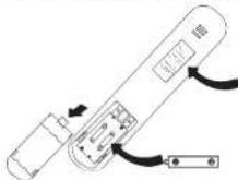
Replacement of Batteries
Remove the battery cover plate from the rear of the remote controller, by sliding it in the direction of the arrow.
Install the batteries according the direction (+and -) shown on the Remote Controller.
Reinstall the battery cover by sliding it into place.
Use 2 LRO 3 AAA (1.5V) batteries. Do not use rechargeable batteries. Replace the old batteries with new ones of the same type when the display is no longer legible. Do not dispose batteries as unsorted municipal waste. Collection of such waste separately for special treatment is necessary.
Note Child-lock:Press ∨ and ∧ together to active.
Display ON/OFF: Long press ECO button
Please remove batteries to avoid leakage damage when not using for a long time.
When you insert the batteries for the first time in the remote controller or if you change them, you can program the remote controller of only cooling or cooling and heating. 1. Long press MODE button over 5s to get into the change mode within 3 minutes;
- Press MODE button to change COOL or HEAT.
NOTE: If you adjust the remote controller in cooling mode, it will not be possible to activate the heating function in units with heating pump. you need to take out the batteries and repeat the procedure described above.
When you insert the batteries for the first time in the remote controller or if you change them, you can program the temperature display switchover function between ^13C and ^14F .
-
Long press TURBO button over 5s to get into the change mode within 3 minutes;
-
Press TURBO button to change °C and °F
-
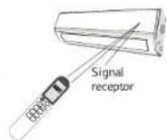
Direct the remote controller toward the Air conditioner.
- Check that there are no objects between the remote control and the Signal receptor in the indoor unit.
- Never leave the remote controller exposed to the rays of the sun.
- Keep the remote controller at a distance of at least 1m from the television or other electrical appliances.
OPERATING INSTRUCTIONS
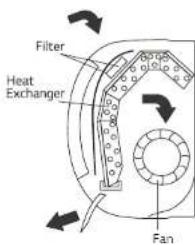
The air sucked by the fan enters from the grill and passes through the filter, then it is cooled/dehumidified or heated through the heat exchanger.
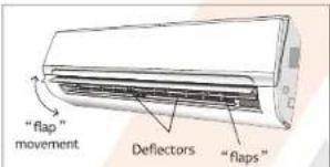
The direction of the air outlet is motorized up and down by flaps, and manually moved right and left by the vertical deflectors, for some models, the vertical deflectors could be controlled by motor as well.
"SWING "CONTROL OF THE AIR FLOW
- Press the button | | to activate the “FLAP”, (1) If press time interval is in 2 seconds, the swing will cycle as below. | | | | | | deactivate
(2) If long press the button, the swing angle range of horizontal flap will cycle as below: ' ' - _- _1
(3) If press time interval is over 2 seconds, it will be deactivate the air flow is directed alternatively from up to down. In order to guarantee an even diffusion of the air in the room.
- Press the button to activate the motorized "deflectors" (1) If press time interval is in 2 seconds, the swing will cycle as below:
(2) If long press the button, the swing will cycle as below:
(3) If press time interval is over 2 seconds, it will be deactivate the air flow is directed alternatively from left to right. (Optional function, depends on the models)
The deflectors are positioned manually and placed under the flaps. They allow to direct the air flow rightward or leftward.
This adjustment must be done while the appliance is switched off.
Never position "Flaps" manually, the delicate mechanism might seriously damaged!
Never poke fingers, sticks or other objects in the air inlet or outlet vents. Such accidental contact with live pants might cause unforeseeable damage or hurt.
OPERATING INSTRUCTIONS
COOLING MODE
5.00
The cooling function allows the air conditioner to cool the room and at the same time reduces Air humidity.
To activate the cooling function (COOL), press the MODE button until the symbol COOL appears on the display.
The cooling function is activated by setting the button▼ or ▲ at a temperature lower than that of the room.
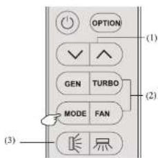
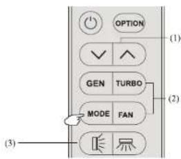
To optimize the function of the Air conditioner, adjust the temperature (1), the speed (2) and the direction of the air flow (3) by pressing the button indicated.
HEATING MODE
HEAT
The heating function allows the air conditioner to heat the room.
To activate the heating function (HEAT), press the MODE button until the symbol HEAT appears on the display.
With the button▼ or ▲ set a temperature higher than that of the room.
To optimize the function of the Air conditioner adjust the temperature (1), the speed (2) and the direction of the air flow (3) by pressing the button indicated

In HEATING operation, the appliance can automatically activate a defrost cycle, which is essential to clean the frost on the condenser so as to recover its heat exchange function. This procedure usually lasts for 10-2 minutes during defrosting, indoor unit fan stop operation. After defrosting, it resumes to HEATING mode automatically.
DRY MODE
DRY
This function reduces the humidity of the air to make the room more comfortable.
To set the DRY mode, Press MODE until DRY appears in the display. An automatic function of alternating cooling cycles and air fan is activated.
OPERATING INSTRUCTIONS
FAN MODE(Not FAN button)
FAN
The air conditioner works in only ventilation.
To set the FAN mode, Press MODE until FAN appears on the display
To optimize the function of the air conditioner, adjust the temperature(1), the speed (2) and the direction of the air flow (3) by pressing the buttons indicated.
AUTO MODE
AUTO
Automatic mode
To activate the AUTO mode of operation, press the MODE button on the remote controller until the symbol AUTO appears on the display.
In AUTO mode the run mode will be set automatically according to the room temperature.
To optimize the function of the air conditioner, adjust the temperature(1), the speed (2) and the direction of the air flow (3) by pressing the buttons indicated.
DISPLAY function (Indoor display)
[DIS PLAY]
Switch on/off the LED display on panel
Press OPTION at the fist time, select the DISPLAY by pressing the button or until symbol DISPLAY is flashing. Press OPTION again to switch off the LED display on the panel, and DRPLA appears on the remote controller display. Do it again to switch on the LED display.
SLEEP function
[SLE EP]
Press OPTION at the first time, select the SLEEP by pressing the button ↗ or ∨ until symbol SLEEP is flashing; Press OPTION again to activate the SLEEP function, and SLEEP appears on the display. Do it again to deactivate this function
After 10 hours running in sleep mode the air conditioner is swicthed off automatically.
OPERATING INSTRUCTIONS
GEN function(Optional)
GEN
The air conditioner works in GEN mode
Through GEN mode, you can choose the current level of the unit. There are three levels (L1, L2, L3) in this mode, and the current increases in turn.
To activate GEN function, pressing the button GEN and the unit current level will cycle as below OFF → L3 → L2 → L1"
To cancel this function, press the GEN until code OFF appears on the display
ECO function
ECO
In this mode the appliance automatically sets the operation to achieve energy savings.
- Press the "ON / OFF" button to turn on appliance and select a COOLING / HEATING mode.
- Press the "ECO" button, the appliance will run in ECO mode.
- Pressing the "ECO" button again will open the mode. "ECO"
- Pressing the 'ECO' button again will cancel the mode, ECO will no longer be shown on the LCD screen.
NOTE:
The ECO function is available in COOLING and HEATING modes.
Turbo function

To activate turbo function, pressing the button TURBO or pressing the button FAN until symbol 🤨 appears on the display
To cancel this function, pressing the F AN to switch other fan speed or pressing the TURBO button again.
In AUTO/HEA T/COOL/FAN mode, When you select TURBO feature, it will use the highest fansetting to blowstrong airflow
OPERATING INSTRUCTIONS
TIMER function

To set the automatic switch-on /off of the air conditioner
Timer setting/change/cancel:
1. Press OPTION at the first time, select the Timer by pressing the button\~ or\~ until symbol TIMER is flashing;
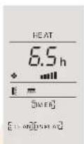
2. Press OPTION again, the datasymbol like 6.5 and TIMER will be flashing;
3. To set the timer or change the timer:
(1) Press the button or to set the expected timer (Increase or decrease at half-hour intervals) the symbols h and TIMER both are flashing.
(2) Press OPTION or waiting for 5 seconds without any operation to confirm the timer, the pre-setting timer like 8.5, and symbol [MRE] will be on the display.
- To cancel the timer(if TIMER is on)
Repeat step 1, step 2, then press OPTION or waiting for 5 seconds without any operation to cancel the timer.
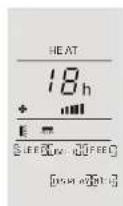
A sample for the Timer-on as Figure1, Timer-off as Figure2
Note:
All processing should be operated in 5 seconds, otherwise the processing will be cancelled.
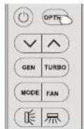
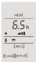
Figure1, Timer-on when switch off
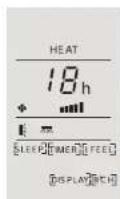
Figure2,Timer-off when switch on
FEEL function (Optional)

Press OPTION at the first time, select the I FEEL by pressing the button\~ or \~ until symbol I FEEL is flashing; Press OPTION again to activate the I FEEL function, and FEE appears on the display. Do it again to deactivate this function.
This function enable the remote control to measure the temperature atts current location and send this signal 7 times in 2 hours to the air conditioner to enable the air conditioner to optimize the temperature around you and ensure maximum comfort. It will automatically deactivate 2 hours later.
OPERATING INSTRUCTIONS
MILDEW function (Optional)
[MUDEW]
Press OPTION at the first time, select the MILDEW by
pressing the button\~ or \~ until symbol MILDEW is flashing; Press OPTION again to activate the
MILDEW function, and [MILDEW] appears on the display.
Do it again to deactivate this function.
This function enable the air conditioner still blow airflow about 15 minutes to dry the indoor inner parts to avoid mildew, when the air conditioner is off
Note: MILDEW function only available in DRY/COOLING mode
SELF-CLEAN function (Optional)
[CLEAN]
Switch off the air conditioner by pressing
Press OPTION at the first time, select the CLEAN by pressing the button^ or \~ until symbol CLEAN is flashing; Press OPTION again to activate the CLEAN function, and [CLEAN] appears on the display. Do it again to deactivate this function.
- This function help carry away the accumulated dirt, bacteria, etc from the evaporator.
- This function will run about 30 minutes, and it will return to the pre-setting mode. You can press Ⓐ to cancel this function during the progress. You will bear 2 booms when it's finished or cancelled.
- It's normal if there are some noise during this function process,
as plastic materials expand with heat and contract with cold - We suggest operate this function as the following ambient condition to avoid certain safety protection features.
| Indoor unit | Temp<30°C |
| Outdoor unit | 5°C |
- We suggest operate this function per 3 months.
8°C heating function (Optional)
[B°CH]
It can be set in Cool/Heat/Dry/Fan/Auto mode, but you need to turn off the unit reactivate it.
-
Press OPTION at the first time, select the 8 °C H by
pressing the button^ or\~ until symbol 8 °C H
is flashing: Press OPTION again to choose the 8°C heating function, and [8°C H] appears on the display. Do it again or change the mode to deactivate this function -
If the air conditioner is standby, this function enable the air conditioner automatically start heating when the indoor temperature is equal or lower than 8°C, it will return standby if the temperature is equal or higher than 18°C.
PROTECTION
Operating Temperature
The air conditioner is programmed for comfortable and suitable living conditions as below if used outside the conditions, certain safety protection features might come into effect. Fix air conditioner:
| Temperature\MODE | Cooling operating | Heating operating | Drying operating |
| Room temperature | 17°C~32°C | 0°C~27°C | 18°C~32°C |
| Outdoor temperature | 0°C~43°CFor T1 Climate | -7°C~24°C | 0°C~50°C |
| 0°C~52°CFor T3 Climate |
Inverter air conditioner:
| Temperature\MODE | Cooling operating | Heating operating | Drying operating |
| Room temperature | 17°C~32°C | 0°C~30°C | 10°C~32°C |
| Outdoor temperature | 0°C~53°C | -15°C~30°C | 0°C~50°C |
| -15°C~53°CFor models with low temperature cooling system |
The unit does not operate immediately if it is turned on after being turned off or after changing the mode during operation. This is a normal self-protection action, you need waiting for about 3 minutes.
The capacity and efficiency are according to the test conducted at full-load operation*. *The highest speed of indoor fan motor and the maximum open angle of the flaps and deflectors are requested.
INSTALLATION MANUAL---Selecting the installation Place
INDOOR UNIT
• Install the indoor unit on a strong wall that is not subject to vibrations.
• The in let and outlet ports should not be obstructed: the air should be able to blow all over the room.
- Do not install the unit near a source of heat, steam, or flammable gas.
- Install the unit near an electric socket or private circuit.
- Do not install the unit where it will be exposed to direct sunlight.
- Select a site where the condensed water can be easily drained out, and where it is easily connected to outdoor unit.
- Check the machine operation regularly and reserve the necessary spaces as shown in the picture.
- Select a place where the filter can be easily taken out.
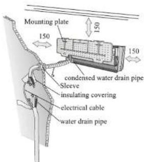
minimum space to be reserved (mm) showing in the picture
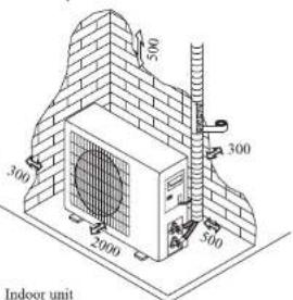
OUTDOOR UNIT
- Do not install the outdoor unit near sources of heat, steam or flammable gas.
- Do not install the unit in too windy or dusty places.
- Do not install the unit where people often pass. Select a place where the air discharge and operating sound will not disturb the neighbours.
- Avoid installing the unit where it will be exposed to direct sunlight (other wise use a protection, if necessary, that should not interfere with the air flow).
- Reserve the spaces as shown in the picture for the air to circulate freely.
• Install the outdoor unit in a safe and solid place. - If the outdoor unit is subject to vibration, place rubber gaskets onto the feet of the unit..
Installation Diagram
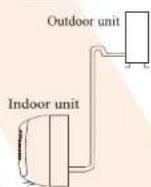
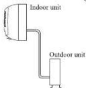
The purchaser must ensure that the person and/or company who is to install, maintain or repair this air conditioner has qualifications and experience in refrigerant products.
INSTALLATION MANUAL---Installation of the Indoor unit
Before starting installation, decide on the position of the indoor and outdoor units, taking into account the minimum space reserved around the units
Do not install your air conditioner in a wet room such as a bathroom or laundry etc
The installation site should be 250cm or more above the floor.
To install, proceed as follows:
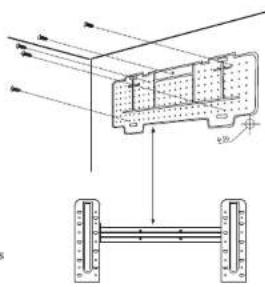
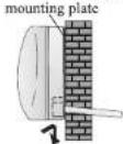
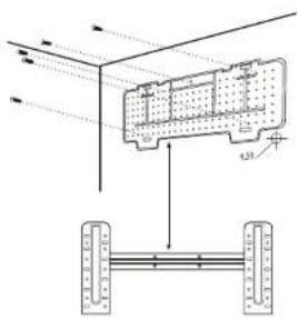
Installation of the mounting plate
I Always mount the rear panel horizontally and vertically
2. Drill 32 mm deep holes in the wall to fix the plate;
3. Insert the plastic anchors into the hole;
4. Fix the rear panel on the wall with provided tapping screws
5. Be sure that the rear panel has been fixed firmly enough to withstand the weight
Note: The shape of the mounting plate may be different from the one above, but installation method is similar.
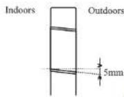
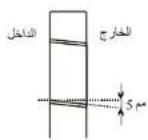
Drilling a hole in the wall for the piping
- Make the piping hole (Φ55) in the wall at a slight downward slant to the outdoor side.
- Insert the piping-hole sleeve into the hole to prevent the connection piping and wiring from being damaged when passing through the hole.
The hole must slope downwards towards the exterior
Note : Keep the drain pipe down towards the direction of the wall hole, otherwise leakage may occur.
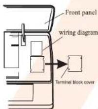
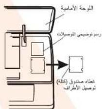
Electrical connections—Indoor unit
- Open the front panel.
- Take off the cover as indicated in the picture (by removing a screw or breaking the hooks).
- For the electrical connections, see the circuit diagram on the right part of the unit under the front panel.
- Connect the cable wires to the screw terminals by following the numbering, Use wire size suitable to the electric power input (see name plate on the unit) and according to all current national safety code requirements.
The cable connecting the outdoor and indoor units must be suitable for outdoor use.
The plug must be accessible also after the appliance has been installed so that it can be pulled out if necessary.
An efficient earth connection must be ensured.
⚠️ If the power cable is damaged, it must be replaced by an authorised Service Centre.
Note: Optional the wires can be connected to the main PCB of indoor unit by manufacturer according to the model without terminal block.
INSTALLATION MANUAL---Installation of the Indoor unit
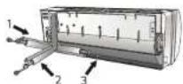
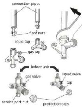
Refrigerant piping connection
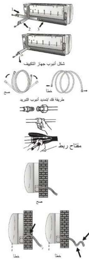
The piping can be run in the 3 directions indicated by numbers in the picture. When the piping is run in direction 1 or 3, cut a notch along the groove on the side of the indoor unit with a cutter.
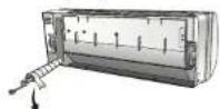
Run the piping in the direction of the wall hole and bind the copper pipes, the drain pipe and the power cables together with the tape with the drain pipe at the bottom, so that water can flow freely.
- Do not remove the cap from the pipe until connecting it, to avoid dampness or dirt from entering.
- If the pipe is bent or pulled too often, it will become stiff. Do not bend the pipe more than three times at one point.
- When extending the rolled pipe, straighten the pipe by unwinding it gently as shown in the picture.
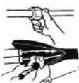
Connections to the indoor unit
- Remove the indoor unit pipe cap (check that there is no debris inside).
- Insert the fare nut and create a flange at the extreme end of the connection pipe.
- Tighten the connections by using two wrenches working in opposite directions
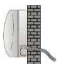
Indoor unit condensed water drainage
The indoor unit condensed water drainage is fundamental for the success of the installation.
- Place the drain hose below the piping, taking care not to create siphons.
- The drain hose must slant downwards to aid drainage.
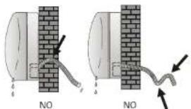
- Do not bend the drain hose or leave it protruding or twisted and do not put the end of it in water. If an extension is connected to the drain hose, ensure that it is lagged when it passes into the indoor unit.
- If the piping is installed to the right, the pipes, power cable and drain hose must be lagged and secured onto the rear of the unit with a pipe connection.
1) Insert the pipe connection into the relative slot.
2) Press to join the pipe connection to the base.
Shape the connection pipe
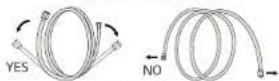
Extending the rolled pipe
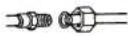
YES
INSTALLATION MANUAL---Installation of the Indoor unit
INSTALLATION OF THE INDOOR UNIT
After having connected the pipe according to the instructions, install the connection cables. Now install the drain pipe. After connection, lag the pipe, cables and drain pipe with the insulating material.
- Arrange the pipes, cables and drain hose well.
- Lag the pipe joints with insulating material, securing it with vinyl tape.
- Run the bound pipe, Cables and drain pipe through the wall hole and mount the indoor unit onto the upper part of the mounting plate securely.
- Press and push the lower part of the indoor unit tightly against the mounting plate
09
Covered by vinyl tape
INSTALLATION MANUAL---Installation of the outdoor unit
• The outdoor unit should be installed on a solid wall and fastened securely.
- The following procedure must be observed before connecting the pipes and connecting cables: decide which is the best position on the wall and leave enough space, to be able to carry out maintenance easily.
- Fasten the support to the wall using screw anchors which are particularly suited to the type of wall;
- Use a larger quantity of screw anchors than normally required for the weight they have to bear to avoid vibration during operation and remain fastened in the same position for years without the screws becoming loose.
- The unit must be installed following the national regulations.
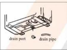
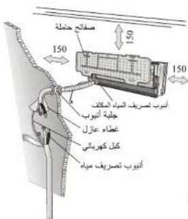
Outdoor unit condensed water drainage (only for heat pump models)
The condensed water and the ice formed in the outdoor unit during heating operation can be drained away through the drain pipe
- Fasten the drain port in the 25mm hole placed in the part of the unit as shown in the picture.
- Connect the drain port and the drain pipe. Pay attention that water is drained in a suitable place.
INSTALLATION MANUAL---Installation of the outdoor unit
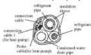
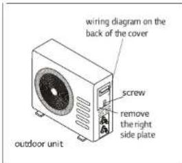
ELECTRICAL CONNECTIONS
- Remove the handle on the right side plate of outdoor unit.
- Connect the power connection cord to the terminal board. Wiring should fit that of indoor unit.
- Fix the power connection cord with wire clamp.
- Confirm if the wire has been fixed properly.
- An efficient earth connection must be ensured.
- Recover the handle
CONNECTING THE PIPES
Screw the flare nuts to the outdoor unit coupling with the same tightening procedures described for the indoor unit.
To avoid leakage, pay attention to the following points:
- Tighten the flare nuts using two wrenches. Pay attention not to damage the pipes.
- If the tightening torque is not sufficient, there will probably be some leakage. With excessive tightening torque there will also be some leakage, as the flange could be damaged.
- The surest system consists in tightening the connection by using a fix wrench and a torque wrench in this case use the table on page 24.
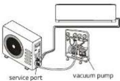
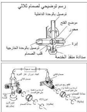
BLEEDING
Air and humidity left inside the refrigerant circuit can cause compressor malfunction. After having connected the indoor and outdoor units, bleed the air and humidity from the refrigerant circuit by using a vacuum pump.
INSTALLATION MANUAL---Installation of the outdoor unit
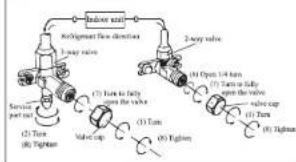
BLEEDING
The air and humidity left inside the refrigerant circulation can cause compressor malfunction. After having connected the indoor and outdoor units, bleed the air and humidity from the refrigerant circulation using a vacuum pump.
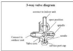
(1) Unscrew and remove the caps from the 2-way and 3-way valves.
(2) Unscrew and remove the cap from the service port. (3) Connect the vacuum pump hose to the service port.
(4) Operate the vacuum pump for 10 - 15 minutes until an absolute vacuum of 10 mm. He has been reached.
(5) With the vacuum pump still in operation, close the low-pressure knob on the vacuum pump coupling. Stop the vacuum pump.
(6) Open the 2 - way valve by 1/4 turn and then close it after 10 seconds. Check all the joints for leaks using liquid soap or an electronic leak device.
(7) Turn the body of the 2-way and 3-way valves. Disconnect the vacuum pump hose.
(8) Replace and tighten all the caps on the valves.
flowchart
graph TD
    A["Inlet valve"] --> B["8x10mm inlet direction"]
    B --> C["1-way valve"]
    C --> D["2-way valve"]
    D --> E["3-way valve"]
    E --> F["4-way valve"]
    F --> G["5-way valve"]
    G --> H["6-way valve"]
    H --> I["7-way valve"]
    I --> J["8-way valve"]
    J --> K["9-way valve"]
    K --> L["10-way valve"]
    L --> M["11-way valve"]
    M --> N["12-way valve"]
    N --> O["13-way valve"]
    O --> P["14-way valve"]
    P --> Q["15-way valve"]
    Q --> R["16-way valve"]
    R --> S["17-way valve"]
    S --> T["18-way valve"]
    T --> U["19-way valve"]
    U --> V["20-way valve"]
INSTALLATION MANUAL--- operation test
- Wind insulating covering around the joints of the indoor unit and fix it with insulating tape.
- Fix the exceeding part of the signal cable to the piping or to the outdoor unit.
- Fix the piping to the wall (after having coated it with insulating tape) using clamps or insert them into plastic slots.
- Seal the hole in the wall through which the piping is passed so that no air or water can fill.
Indoor unit test
- Do the ON/OFF and FAN operate normally?
- Does the MODE operate normally?
- Do the set point and TIMER function properly?
- Does each lamp light normally?
- Do the flap for air flow direction operate normally?
- Is the condensed water drained regularly?
Outdoor unit test
• Is there any abnormal noise or vibration during operation?
- Could the noise, the air flow or the condensed water drainage disturb the neighbours? - Is there any coolant leakage?
Note: the electronic controller allows the compressor to start only three minutes after voltage has reached the system.

INSTALLATION MANUAL---Information for the installer
| FIXED-SPEED TYPEMODEL capacity (Btu/h) | 5k | 7k | 9k | 12k | 15/18k | 22/24k | 28/30k/36k |
| Liquid pipe diameter | 4/1*(±6) | 4/1*(±6) | 4/1*(±6) | 4/1*(±6) | 4/1*(±6) | 8/3*(±9.52) | 8/3*(±9.52) |
| Gas pipe diameter | 8/3*(±9.52) | 8/3*(±9.52) | 8/3*(±9.52) | 2/1*(±12) | 2/1*(±12) | 8/5*(±15.88) | 8/5*(±15.88) |
| Length of pipe with standard charge | 3m | 3m | 3m | 3m | 4m | 4m | 4m |
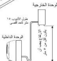
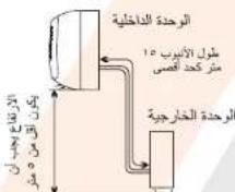
| Maximum distance between indoor and outdoor unit | 15m | 15m | 15m | 15m | 15m | 15m | 15m |
| Additional refrigerant charge | 20g/m | 20g/m | 20g/m | 20g/m | 30g/m | 30g/m | 30g/m |
| Max. diff. in level between indoor and outdoor unit | 5m | 5m | 5m | 5m | 5m | 5m | 5m |
| Type of refrigerant(1) | R22 | R22 | R22 | R22 | R22 | R22 | R22 |
| FIXED-SPEED TYPEMODEL capacity (Btu/h) | 7k | 9k | 12k | 15/18k | 22/24k | 28/30k/36k | |
| Liquid pipe diameter | 4/1*(±6) | 4/1*(±6) | 4/1*(±6) | 4/1*(±6) | 8/3*(±9.52) | 8/3*(±9.52) | |
| Gas pipe diameter | 8/3*(±9.52) | 8/3*(±9.52) | 8/3*(±9.52) | 2/1*(±12) | 8/5*(±15.88) | 8/5*(±15.88) | |
| Length of pipe with standard charge | 3m | 3m | 3m | 4m | 4m | 4m | |
| Maximum distance between indoor and outdoor unit | 15m | 15m | 15m | 15m | 15m | 15m | |
| Additional refrigerant charge | 20g/m | 20g/m | 20g/m | 30g/m | 30g/m | 30g/m | |
| Max. diff. in level between indoor and outdoor unit | 5m | 5m | 5m | 5m | 5m | 5m | |
| Type of refrigerant(1) | R410A | R410A | R410A | R410A | R410A | R410A | |
| INVERTER TYPEMODEL capacity (Btu/h) | 9k | 12k | 15/18k | 22/24k | |
| Liquid pipe diameter | 4/1^* ( 6 ) | 4/1^* ( 6 ) | 4/1^* ( 6 ) | 8/3^* ( 9.52 ) | |
| Gas pipe diameter | 8/3^* ( 9.52 ) | 8/3^* ( 9.52 ) | 2/1^* ( 12 ) | 2/1^* ( 12 ) | 8/5^* ( 15.88 ) |
| Length of pipe with standard charge | 3m | 3m | 3m | 4m | 4m |
| Maximum distance between indoor and outdoor unit | 15m | 15m | 15m | 15m | 15m |
| Additional refrigerant charge | 20g/m | 20g/m | 20g/m | 30g/m | 30g/m |
| Max diff. in level between indoor and outdoor unit | 5m | 5m | 5m | 5m | 5m |
| Type of refrigerant(1) | R410A | R410A | R410A | R410A | R410A |
(1) Refer to the data rating label sticked on the outdoor unit.
TIGHTENING TORQUE FOR PROTECTION CAPS AND FLANGE CONNECTION
| PIPE | TIGHTENING TORQUE [N x m] | CORRESPONDING STRESS (using a 20 cm wrench) | TIGHTENING TORQUE [N x m] | |
| 4/1" (Φ6) | 20 - 15 | wrist strength | Service port nut | 9 - 7 |
| 8/3" (Φ9.52) | 35 - 31 | arm strength | Protection caps | 30 - 25 |
| 2/1" (Φ12) | 45 - 35 | arm strength | ||
| 8/5" (Φ15.88) | 80 - 75 | arm strength |
INSTALLATION MANUAL---Installation for the installer
WIRING DIAGRAM
For different models, the wiring diagram may be different. Please refer to the wiring diagrams pasted on the indoor unit and outdoor unit respectively.
On indoor unit, the wiring diagram is pasted under the front panel;
On outdoor unit, the wiring diagram is pasted on the backside of the outdoor handle cover.
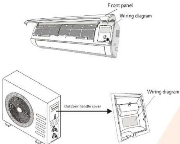
Note: For some models the wires has been connected to the main PCB of indoor unit by manufacturer without terminal block.
INSTALLATION MANUAL---Information for the installer
CABLE WIRES SPECIFICATION
| MODEL capacity (Btu/h) | 5k | 7k | 9k | 12k | 15/18k | 22/24k | 28/30k/36k | |
| sectional area | ||||||||
| Power supply cable | N | 1.0mm^2 AWG18 | 1.0mm^2 AWG18 | 1.0mm^2 AWG18 | 1.0mm^2(1.5mm^2) AWG18(AWG16) | 1.5mm^2 AWG16 | 2.5mm^2 AWG14H05RN-F | 4.0mm^2 AWG12 |
| L | 1.0mm^2 AWG18 | 1.0mm^2 AWG18 | 1.0mm^2 AWG18 | 1.0mm^2(1.5mm^2) AWG18(AWG16) | 1.5mm^2 AWG16 | 2.5mm^2 AWG14H05RN-F | 4.0mm^2 AWG12 | |
| E | 1.0mm^2 AWG18 | 1.0mm^2 AWG18 | 1.0mm^2 AWG18 | 1.0mm^2(1.5mm^2) AWG18(AWG16) | 1.5mm^2 AWG16 | 2.5mm^2 AWG14H05RN-F | 4.0mm^2 AWG12 | |
| Connection supply cable | N | 1.0mm^2 | 1.0mm^2 | 1.0mm^2 | 1.0mm^2(1.5mm^2) | 1.5mm^2 | 0.75mm^2 | 0.75mm^2 |
| L | 1.0mm^2 | 1.0mm^2 | 1.0mm^2 | 1.0mm^2(1.5mm^2) | 1.5mm^2 | 0.75mm^2 | 0.75mm^2 | |
| 1 | 1.0mm^2 | 1.0mm^2 | 1.0mm^2 | 1.0mm^2(1.5mm^2) | 1.5mm^2 | 0.75mm^2 | 0.75mm^2 | |
| 2 | 0.75mm^2 | 0.75mm^2 | 0.75mm^2 | 0.75mm^2 | 0.75mm^2 | 0.75mm^2 | 0.75mm^2 | |
| 3 | 0.75mm^2 | 0.75mm^2 | 0.75mm^2 | 0.75mm^2 | 0.75mm^2 | 0.75mm^2 | 0.75mm^2 | |
| 0.75mm^2 | 0.75mm^2 | 0.75mm^2 | 0.75mm^2 | 0.75mm^2 | 0.75mm^2 | 0.75mm^2 | ||
| INVERTER TYPEMODEL capacity (Btu/h) | 9k | 12k | 18/22k | 24k | ||||
| sectional area | ||||||||
| Power supply cable | N | 1.0mm^3 (1.5mm^3) AWG18(AWG16) | 1.0mm^3 (1.5mm^3) AWG18(AWG16) | 1.5mm^3 AWG16 | 2.5mm^3 AWG14 | |||
| L | 1.0mm^3 (1.5mm^3) AWG18(AWG16) | 1.0mm^3 (1.5mm^3) AWG18(AWG16) | 1.5mm^3 AWG16 | 2.5mm^3 AWG14 | ||||
| E | 1.0mm^3 (1.5mm^3) AWG18(AWG16) | 1.0mm^3 (1.5mm^3) AWG18(AWG16) | 1.5mm^3 AWG16 | 2.5mm^3 AWG14 | ||||
| Connection supply cable | N | 1.0mm^3 (1.5mm^3) | 1.0mm^3 (1.5mm^3) | 1.5mm^3 | 0.75mm^3 | |||
| L | 1.0mm^3 (1.5mm^3) | 1.0mm^3 (1.5mm^3) | 1.5mm^3 | 0.75mm^3 | ||||
| I | 1.0mm^3 (1.5mm^3) | 1.0mm^3 (1.5mm^3) | 1.5mm^3 | 0.75mm^3 | ||||
| 1.0mm^3 (1.5mm^3) | 1.0mm^3 (1.5mm^3) | 1.5mm^3 | 0.75mm^3 | |||||
220V 7K, 9K, 12K 15K, 16K, 18K, 22K, 24K, 30K air conditioner indoor unit fuse parameter is 50T, 3.15A
110V 7K, 9K 12k air conditioner indoor unit fuse parameter is 50T, 3.15A,
125V 7K,9K,12K air conditioner outdoor unit fuse parameter is 61T,15A
250V 18K, 22K, 24K air conditioner outdoor unit fuse parameter is 65TS, 25A
MAINTENANCE
Periodic maintenance is essential for keeping your air conditioner efficient.
Before carrying out any maintenance, disconnect the power supply by taking the plug out from the socket.
INDOOR UNIT
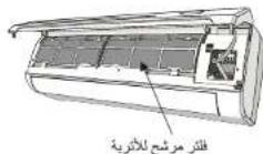
ANTIDUST FILTERS
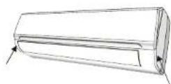
- Open the front panel following the direction of the arrow
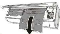
- Keeping the front panel raised with one hand, take out the air filter with the other hand
- Clean the filter with water; if the filter is soiled with oil, it can be washed with warm water (not exceeding 45°C). Leave to dry in a cool and dry place.
- Keeping the front panel raised with one hand, insert the air filter with the other hand
- Close
The electrostatic and the deodorant filter (if installed) cannot be washed or regenerated and must be replaced with new filters after every 6 months.
CLEANING THE HEAT EXCHANGER
- Open the front panel of the unit and life it till its greatest stroke and then unhooking it from the hinges to make the cleaning easier.
- Clean the indoor unit using a cloth with the water (not higher than 40°C) and neutral soap. Never use aggressive solvents or detergents.
- If the outdoor unit is clogged, remove the leaves and the waste and remove the dust with air jet or a bit of water.
END OF SEASON MAINTENANCE
- Disconnect the automatic sw
- Clean and replace the filters
- On a sunny day let the conditioner work in ventilation for some hours, so that the inside of the unit can dry completely..
REPLACING THE BATTERIES
When: • There is no confirmation beep heard from the indoor unit.
• The LCD doesn't act.
How: • Take off the cover at back.
- Place the new batteries respecting the symbols + and - .
N.B: Use only new batteries. Remove the batteries from the remote controller when the conditioner is not in operation
WARNING! Do not throw batteries into common rubbish, they should be disposed of in the special containers situated in the collection points.
TROUBLESHOOTING
| MALFUNCTION | POSSIBLE CAUSES | |
| The appliance does not operate | Power failure/plug pulled out | |
| Damaged indoor/outdoor unit fan motor | ||
| Faulty compressor thermomagnetic circuit breaker | ||
| Faulty protective device or fuses. | ||
| Loose connections or plug pulled out | ||
| It sometimes stops operating to protect the appliance. | ||
| Voltage higher or lower than the voltage range | ||
| Active TIMER-ON function | ||
| Damaged electronic control board | ||
| Strange odour | Air filter dirty | |
| Noise of running water | Back flow of liquid in the refrigerant circulation | |
| A fine mist comes from the air outlet | This occurs when the air in the room becomes very cold, for example in the “COOLING” or “DEHUMIDIFYING/DRY” modes. | |
| A strange noise can be heard | This noise is made by the expansion or contraction of the front panel due to variations in temperature and does not indicate a problem. | |
| Insufficient airflow, either hot or cold | Inappropriate temperature setting.. | |
| Air inlet or outlet of indoor or outdoor unit has been blocked. | ||
| Air filter is blocked. | ||
| Fan speed set at minimum. | ||
| Other sources of heat in the room. | ||
| No refrigerant. | ||
| The appliance does not respond to commands | Remote control is not near enough to indoor unit. | |
| Battery in Remote controller may have been exhausted.. | ||
| Obstacles between remote control and signal receiver in indoor unit. | ||
| The display is off | Active LED function | |
| Power failure | ||
| Switch off the air conditioner immediately and cut off the power supply in the event of: | ||
| Strange noises during operation. | ||
| Faulty electronic control board | ||
| Faulty fuses or switches. | ||
| Spraying water or objects inside the appliance. | ||
| Overheated cables or plugs. | ||
| Very strong smells coming from the appliance. | ||
| ERROR SIGNALS ON THE DISPLAY | ||
| In case of error, the display on the indoor unit shown the following error codes: | ||
| RUN lamp | Description of the trouble | |
| E1 | flashes once | The fault of indoor temperature sensor |
| E2 | flashes twice | The fault of indoor pipe temperature sensor |
| E6 | flashes 6 times | Malfunction of indoor fan motor. |
| E4 | Display code | Refrigerant leakage |
معلجة المشاكل
| ال습ب المouchتلم | العطل | ||
| عمل كهرباني / قابس للكهرباء مزوع | الجهاز لا يعمل | ||
| م司机 المروحة النachaية / pharmacية مpoint | |||
| فاطع الدارة ( المCONTاطيسي - الحرatie) ل microscopyب المضط معمل | |||
| تعمل قاطع التبار ( الغوز) أو أحيزة الحمالية | |||
| وصيات عير م VOLCCA ( HRZA ) أو قابس الكهرباء مسوح بال創造 | |||
| في ب impost Contractة نام إيفق التشELL ب express حمالية جهاز | |||
| الفرات ( الجده الكهربي ) أعلى أو Micن من المعلي الطимиي | |||
| خاسية الموقت وقي وضمن الشغيل | |||
| لارحة التموكت الادترنية محلطة | |||
| قطر غير تنيف | راستحة غريبية | ||
| ارشجع تيار صQUIف المياه من دائرة التبريد | صوigt جر JEAN مياه | ||
| ها NGOت عندما للكون العربية ر征ADA، على سビル المثل في و supportive Yellowstone أو التّفقط | رواز خفيف بخرج من مخرج التبريد | ||
| هذه ضوضات لを通د تناجة لمدن وانكمالا للوجة Affiliate ونتكل تناجة تغير درجة المجرة. Without تNitير لحووت م VOLKATLES | ضوضاء غريبية يمكن ساتعها | ||
| ضطيف غير صاحب لدرجة Marketing | تيار هواه ضQUIف (سواء بارد أو ساخن) | ||
| السنداد في قتحات تخول أو حروج الهواه | |||
| قطر الهواء منش | |||
| سرعة المروحة على المستوى الأئاني | |||
| م槽数 Chadora外汇ى فيرية | |||
| لقصى في غاز التBERID | |||
| جزار التكيم عن بعد يس قربب بما كيمن من ال Jurichte النachaية | الheimerا للا يسبجيب للاوars | ||
| بLPariatات جاز التكيم عن بعد شارف على الاتهاية | |||
| وJOد عواقين جاز التكيم عن بعد و ال Jurichte النachaية | |||
| اليا الإضactionت نعمل | شاشة العرض لا تعمل | ||
| عمل كهرباني | |||
| كم بالعلاك جهاز التكيف على الفوز ومف بصل التبار الكهرباني في الحالات النالية | |||
| حوضاء عربية لثAAA النشعل | |||
| تعمل لاره التكيم الادترنية | |||
| تعمل قاطع Contract (الوز) / المفتاح | |||
| زش ماها OR اشهاي المخري داخل الجهاز | |||
| كلالات و قابس م VOLCCA لدرجة شنده | |||
| راستة عربية جنا تخرج من المهاز | |||
| اشرات الاعトル على الشاشة والتنبيهاات | |||
| في حلالات الاعトル تطهر هده Romeroز علي شاشة 원ichte النachaية | |||
| وصف مشكلة | ضوم ES النش Delhi | ||
| تعمل حهاز استثماع heater Agricultural | youmض مرة وحدة | E1 | |
| تعمل حهاز استثماع heater Agricultural (الأويب) | youmض مراين | E2 | |
| تعمل م司机 المروحة النachaية | youmض 6 مرات | E6 | |
| tersرب المهرdots | الكود عرضن | E4 | |
الصيانة
الصيان الدورية ضرورية للمحافظة على جهاز التكيف بحالة جيدة قبل البده في عملية الصيانة قم يفصل الكهرباء عن للجهاز عن طريق فصل مفتاح توصيل الكهرباء.
الوحدات الداخلية
فلتر مالع للأترية
- فم بقعت اللوحة الأساسية Woolحدة متبها اتجاه السهم
- عل Protectedى اللوحة الأساسية مertoqueة بيد واحدة، اخ Regular قطر الهواه باليد Agricultural
- فم بنتييف الظفر بال permاء، إذا كان المتر مغطي بLPابقة ریت صلية بمکن، علها بهام داقلا في ترید حرازه onc 45 درجة مبایزيوس. اركته في مدار ورجف لیجف.
- ارpeg Valencia Linkالا سبید واحدة، فم يتركه الظفر باليد Agricultural.
- إقلى اللوحة
العتر المزيل للروانج و القتر الكهروستاكي (في حال وج ------------------------------------------------) لا يمكن عصلهم أر إعادة استخدامهم وجب أن Yemen استبندوا ب (/تتر {-} {-} {-} {-} {-} {6 - } {ا شهر
تنظيف أgzاء تبديل الحرارة
-
قم بptyح اللوحة الأساسية للرحدة وارفها حتى نصل إلى حد الفتح الأقصى رقم بلكها من العلاقات لجعل عملية التنظيف أسهل
-
- نظف الوحدة 동اخية بقطعة قسائ ميلة بماه لا تzend حرارته عن أربعين درجة، وصابوين متعدال، لا ت Connectivityά منظفات فل AMPA و منديات
-
- إذاstation اجزاء الوحدة Departagonalية مسند، قم يازالة أوراق الشجر والأوساح والازكية ب KCنخ هواني أو يقليل من الماء
صيانة نهاية الموسم
1 - افصل المفتاح الأوتوماتيكي أو الزع الكبل
-
نظف أو استيكل الفاتر
-
في يوم ملمس قم يتشغيل جهاز التكيف على وضعية التهورية 값誌誌誌 لجهاز化妆品ة كاملة
استبadal البطاريات
مSTE : • الوحدة الداخلية لا تعمل.
لا ibملا LCD.
كيف: لزع الغطاء.
ضع البطاريات الجديدة مع احترام الإشارات (+) و (-).
ملاحظة : يجب استعمال بطارات保健品، ازع FTPارات من جهاز التحكم عن بعد عندما يكون الجهاز لا يعمل تحذير : لا تلفي FTPارات الفارغة في التفابات العادية، يجب أن两项ض في حاويات خ Resource في /. /. /.
دليل التركيب— معلومات تخصص فريق التركيب
حصوص ألماك التوصيلات الك Perryاتية
| 28/30k36k | 22/24k | 15/18k | 12k | 9k | 7k | 5k | (Btu/h) الحoversة | |
| الإستعمال | ||||||||
| 4.0mm2AWG12 | 2.5mm2AWG14H05RN-F | 1.5mm2AWG16 | 1.0mm2(1.5mm2)AWG18(AWG16) | 1.0mm2AWG18 | 1.0mm2AWG18 | 1.0mm2AWG18 | N | الإستعمال الحoversة |
| 4.0mm2AWG12 | 2.5mm2AWG14H05RN-F | 1.5mm2AWG16 | 1.0mm2(1.5mm2)AWG18(AWG16) | 1.0mm2AWG18 | 1.0mm2AWG18 | 1.0mm2AWG18 | L | |
| 4.0mm2AWG12 | 2.5mm2AWG14H05RN-F | 1.5mm2AWG16 | 1.0mm2(1.5mm2)AWG18(AWG16) | 1.0mm2AWG18 | 1.0mm2AWG18 | 1.0mm2AWG18 | E | |
| 0.75mm2 | 0.75mm2 | 1.5mm2 | 1.0mm2(1.5mm2) | 1.0mm2 | 1.0mm2 | 1.0mm2 | N | الإستعمال الحoversة |
| 0.75mm2 | 0.75mm2 | 1.5mm2 | 1.0mm2(1.5mm2) | 1.0mm2 | 1.0mm2 | 1.0mm2 | L | |
| 0.75mm2 | 0.75mm2 | 1.5mm2 | 1.0mm2(1.5mm2) | 1.0mm2 | 1.0mm2 | 1.0mm2 | 1 | |
| 0.75mm2 | 0.75mm2 | 0.75mm2 | 0.75mm2 | 0.75mm2 | 0.75mm2 | 0.75mm2 | 2 | |
| 0.75mm2 | 0.75mm2 | 0.75mm2 | 0.75mm2 | 0.75mm2 | 0.75mm2 | 0.75mm2 | 3 | |
| 0.75mm2 | 0.75mm2 | 0.75mm2 | 0.75mm2 | 0.75mm2 | 0.75mm2 | 0.75mm2 | ||
| 24k | 18/22k | 12k | 9k | (INVERTER) نوعية (Btu /h) الموديل الحملكة | ||||
| العملكة | ||||||||
| 2.5mm^3 AWG14 | 1.5mm^3 AWG16 | 1.0mm^3 ( 1.5mm^3 ) AWG18(AWG16) | 1.0mm^3 ( 1.5mm^3 ) AWG18(AWG16) | N | كبل إمدادات الطقة | |||
| 2.5mm^3 AWG14 | 1.5mm^3 AWG16 | 1.0mm^3 ( 1.5mm^3 ) AWG18(AWG16) | 1.0mm^3 ( 1.5mm^3 ) AWG18(AWG16) | L | ||||
| 2.5mm^3 AWG14 | 1.5mm^3 AWG16 | 1.0mm^3 ( 1.5mm^3 ) AWG18(AWG16) | 1.0mm^3 ( 1.5mm^3 ) AWG18(AWG16) | E | ||||
| 0.75mm^3 | 1.5mm^3 | 1.0mm^3 ( 1.5mm^3 ) | 1.0mm^3 ( 1.5mm^3 ) | N | كبل تمديد الوصلات | |||
| 0.75mm^3 | 1.5mm^3 | 1.0mm^3 ( 1.5mm^3 ) | 1.0mm^3 ( 1.5mm^3 ) | L | ||||
| 0.75mm^3 | 1.5mm^3 | 1.0mm^3 ( 1.5mm^3 ) | 1.0mm^3 ( 1.5mm^3 ) | 1 | ||||
| 0.75mm^3 | 1.5mm^3 | 1.0mm^3 ( 1.5mm^3 ) | 1.0mm^3 ( 1.5mm^3 ) | ⊕ | ||||
50 T荷 7K,9K,12K,15K,16K,18K,22K,24K,30K,36K نوع قطット الناير Walking ل 220 فروت والместخدمات الوحدات الج vegetables ل 250 فروت — نوع قطット الناير Walking ل 250 و LAS 250، يص机体 3.15 50 T荷 7K,9K,12K — نوع قطット الناير Walking ل 110 فروت — نوع قطット الناير Walking ل 110 و LAS 250، يص机体 3.15 61 T荷 7K,9K,12K ل "INVERTER" يص机体 3.15 أ Motors 125، يص机体 3.15 أ Motors 25، يص机体 3.15 65 TS荷 18K,22K,24K — يص机体 3.15
دليل التركيب--- معلومات تخصص فريق التركيب
م soloط الداره الKEODALIA
ف ي XSنف مخット الأسلاك باعTLAF الموديل ، الرجاء الرجوع إلى المخットات الموجودة على الوحدئين الداخلية والخارجية
بالنسبة لمخطط الوحدة الداخلية ،
بِيمكاني إيجاده بše Verde على ملقص أ سقل الواجهاةolinaية،
بينما تم لصق المخسط على الجهة الخلفية لغطاء الوحدة الخارجية
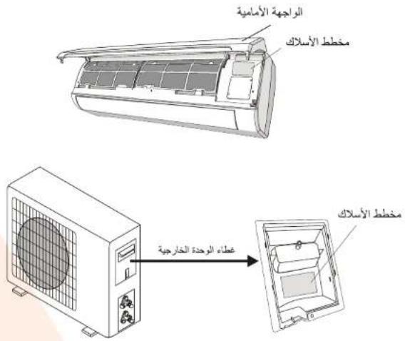
تنبيه : بالنسبة لبعض العوديلات قد تم توصيل الأسلامك بNúmeroة مبائرة إلى كرت الوحدة الداخلية دون إستخدام الوصلة
الخاسة بالأسلاك
دليل التركيب --- معلومات تخصص فريق التركيب
| 28/30k36k | 22/24k | 15/18k | 12k | 9k | 7k | 5k | "FIXED -SPEED "نوعية (Btu/h) الحمولة |
| 3/8 *(Φ 9.52) | 3/8 *(Φ 9.52) | 1/4 *(Φ6) | 1/4 *(Φ6) | 1/4 *(Φ6) | 1/4 *(Φ6) | 1/4 *(Φ6) | قطر عبد بالسال |
| 5/8 *(Φ 15.88) | 5/8 *(Φ 15.88) | 1/2 *(Φ12) | 1/2 *(Φ12) | 3/8 *(Φ 9.52) | 3/8 *(Φ 9.52) | 3/8 *(Φ 9.52) | قطر عبد العاز |
| 4m | 4m | 4m | 3m | 3m | 3m | 3m | طول عبد في التعليمات العالمية |
| 15m | 15m | 15m | 15m | 15m | 15m | 15m | العدد الأقصى للمسافة بين الوحدة الداخليا والخارجية |
| 30g/m | 30g/m | 30g/m | 20g/m | 20g/m | 20g/m | 20g/m | أحمال الغاز الزائدة |
| 5m | 5m | 5m | 5m | 5m | 5m | 5m | أقصى فرق في مستوي المئ Monaco (مز Monaco المئ Monaco) بين الوحدة اطلاعيا والدارجية |
| R22 | R22 | R22 | R22 | R22 | R22 | R22 | نوع التبريت (1) |
| 28/30k36k | 22/24k | 15/18k | 12k | 9k | 7k | "FIXED -SPEED "نوعية (Btu/h) الحمولة | |
| 3/8 *(Φ 9.52) | 3/8 *(Φ 9.52) | 1/4 *(Φ6) | 1/4 *(Φ6) | 1/4 *(Φ6) | 1/4 *(Φ6) | قطر عبد بالسال | |
| 5/8 *(Φ 15.88) | 5/8 *(Φ 15.88) | 1/2 *(Φ12) | 3/8 *(Φ 9.52) | 3/8 *(Φ 9.52) | 3/8 *(Φ 9.52) | قطر عبد الغاز | |
| 4m | 4m | 4m | 3m | 3m | 3m | طول عبد في التعليمات العالمية | |
| 15m | 15m | 15m | 15m | 15m | 15m | العدد الأقصى للمسافة بين الوحدة اطلاعيا والخارجية | |
| 30g/m | 30g/m | 30g/m | 20g/m | 20g/m | 20g/m | أحمال الغاز الزائدة | |
| 5m | 5m | 5m | 5m | 5m | 5m | أقصى فرق في مستوي المئ Monaco (مز Monaco المئ Monaco) من الوحدة اطلاعيا والدارجية | |
| R410A | R410A | R410A | R410A | R410A | R410A | نوع التبريت (1) | |
| 22/24k | 15/18k | 12k | 9k | "INVERTER " (Btu/h) الحoversة | |
| 3/8°(Φ9.52) | 1/4°(Φ6) | 1/4°(Φ6) | 1/4°(Φ6) | قطر آنوب的小Metal | |
| 5/8°(Φ15.88) | 1/2°(Φ12) | 1/2°(Φ12) | 3/8°(Φ9.52) | 3/8°(Φ9.52) | قطر آنوب的大ZR |
| 4m | 4m | 3m | 3m | 3m | فولت آنوب في التعليمات العنية |
| 15m | 15m | 15m | 15m | 15m | الحد الأقصى للمسistance بين الوحدة 달احية والخارجية |
| 30g/m | 30g/m | 20g/m | 20g/m | 20g/m | أ撮ال العاز الزائدة |
| 5m | 5m | 5m | 5m | 5m | القصى فرقي بستانل لثام: عناز المئام) من الوحدة 달احية وال Electricية |
| R410A | R410A | R410A | R410A | R410A | نوع التدريب (1) |
(1) بالاشارة إلى "لوحة القيم" المLouface على الوحدة الخارجية
عزم التدوير لأغطية الحماية و صوامل الربط
| gesture تدوير الربط[m x 7] | الجهد المط-Pacific(using ≥ 20 cm wrench) | Optim تدوير الربط[N x m] | الابوب | |
| 7 - 9 | massage None Def Centre | فرة المخصص | 15 - 20 | 1/4 × ( 6) |
| 25 - 30 | أغليية الحملية | فرة الزراع | 31 - 35 | 3/8 × ( 9.52) |
| فرة الزراع | 35 - 45 | 1/2 × ( 12) | ||
| فرة الزراع | 75 - 80 | 5/8 × ( 15.88) |
دليل التركيب --- تركيب الوحدة الخارجية
القطير
الهواء والرطوبة الموجودين داخل دائرة التب Binary مكمن أن يıldودن إلى عصل في مكسInsManagement، بعد توصيل الوحدة الداخلية والخارجية، فم بتقريف الهواه والرطوبة من دائرة التب Binary باستخدام مضخ سحب هواه.
(1) قم بلك و إزالة غطاء من الصمام الثاني والثلاثي.
(2) قم بلك إزالة الغطاء عن منডّ الخدمة.
(3) قم يتو Pixel خرطوم مضفة سحب الهواه يمنظ الخدمة.
(4) قم بتشغيل مضخة سحب الهواء لمدة من 10 إلى 15 دقيئة
. (10 mm Hg) حُتى تصل إلى حالة التقريع التلم بمعدل
(5) وأثناء عمل مضخة سحب الهواء قم إغلاق مقبض الضغط
المنخفض في المضخة، ثم قم بيّقاف عمل المضخة.
(6) قم بفتح الصمام الثاني بمعدل 4/1 4-2023 تُم قم ياغلاقه بعد 10
تواني، تاكذ من أي تسرب في كل الوصلات باستخدم صابون
ساتل، أو جهاز قياس تسرب الكتروني.
(7) قم يتركيب الصمام الثثاني والثلاثي مرة أخرى، الفصل مضخة
سب الهواء.
(8) قم以便ادة تركيب كل الأغطية و إحكام ربط كل الصامات.
دليل التركيب – المرحلة الأخيرة
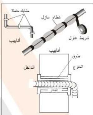
- قم يوضع عازل رياح حول وصلات الوحدة الداخلية وقم
بوضع شریط عازل علیها.
- ثبت الأجزاء الزائدة منKBKL على الموasier أو على الوحدة
الخارجية.
- ثبت الأ nbيب على الجدار (بعد عز نها ب ش ر ي ط ع ا ز ل) ب إستخدام
مشابك أو عن طريق رضعها في mergاري بلاستيكية مخصصة
.
- اغلىق فتحه الجدار التي تمر توصيلة الادwyيب منها، حتى لا ي镝خل مذها أَنْ هُمَاء أَنْ مَاء
.٢٠١٥٣٤٠٠٠
خ-eventار الوحدات الداخليه
(1) (FAN) و (ON/OFF)
• هل زر (MODE) يعمل بصورة طلبيعية?
ال permitsita (TIMER) : هل يعمل
• هل كل الأضراء تعمل بشكل طبيمي؟
• هل جليحات توجية الهواء تعمل بشكل طبيعي؟
• هل الماء المكتف يتم تصريفه بطريقة طبيعية?
الختبار الوحدات الخارجية
• hel weekend أي ضوضاء أو اhetراز غير طبيمي أثناء التشفيل?
• هل الضوضاء، أو تيار الهواء، أو تصريف الماء المكشف يزعج
أحد من الجيران?
• hel هناك أي تسرب للبريدة?
ملحوظة: وحدة التحكم الإلكتروني تسمح لمكيس الضغط أن يبدأ العمل
فقطبعد 3 دقالق من توصيل الكهرباء للنظام.
دليل التركيب --- تركيب الوحدة الخارجية
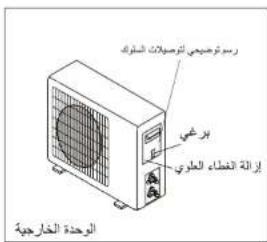
التوصيلات الكهربائية
.1. اتح الغطاء.
- قم بtorsビル الأسلام الكهربائية بن Steps الطريقة التي تمت
بها توصيل الوحدة الداخلية.
- للقيم بالوصيلات الكهربائية، انظر إلى مخط الدائرة
الكهربائية الذي على الجهة الخلفية من الغطاء.
-
قم بربط الأسلامك بواسطة حامل الأسلامك.
-
يجب التأكد من استخدام التوصيل الأرضي
-
اعد الغطاء إلى مكانه.
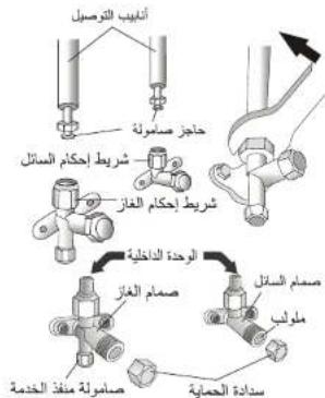
flowchart
graph TD
    A["أبانيب التوصيل"] --> B["خاجز صنولة"]
    B --> C["شربط إحكام السائل"]
    C --> D["شربط إحكام الغاز"]
    D --> E["الوحدة climatesية"]
    E --> F["صمام الغاز"]
    F --> G["صاملة منغّال EXPEDENCE"]
    G --> H["صامولة"]
    H --> I["مولاب"]
    I --> J["صدادة الحماية"]
التوصيلات الكهربالية
قم بريط الصامولة المرسعة على أدابب التوصيل بنفس طريقة
التوصل للوحدة 동اخلية
لتجب التسريب، التبه للنقط التالية:
- قم بربط صامولة التوصيل باستخدام مفتاحي ربط احتر
من إLCAC الضرر بالأنابب.
- إذا لم يُتم الربط بشكل جبذ، قد يحدث بعض التسريب.
و إذا كالت ذلك مبالغة في الربط فسوف يحدث تسريب
أيضا، حيث أن لهابة الأنيوب كد تATTRر.
- الطريقة önemli في ربط الأ nbيب هي باستخدام مفتاح
ربط مفتوح و مفتاح ربط ثابت: في هذه válقة الظّر
الج/mol في failحة 24
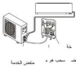
الtersب
كَد يتسب الهواء و الرطروية المحبوсяن في الوحدة الخارجية إلى عدم عملها
جيدا،بعد ايصال الوحدة الداخنية و الخارجية يكون تسرب الهواء و الرطوبة
من دائرة التبريد من خلال Lenخة.
دليل التركيب— تركيب الوحدة الداخلية
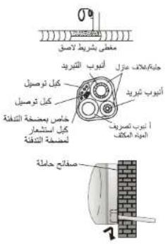
تركيب الوحدة信息公开ية، بعد تركيب الأنياب وفقا للتعليمات، ركيب وصلة الكابلات، قيم بتركيب أنوب الصرف، بعد الترzanب، إنخل بي Oman الأنيوب والكيل و أنوب الصرف داخل الغلاف العازل.
- ترب الأذابب والكابلات و خرطع الصرف بشكل جيد.
- أخ (!ملاة ر Libya的大وب بضه إلى الغالع العزل و قب يتأنيها يشرب لاصق)
- م (%ر الأذابب المروطة والكابلات و أوب الصرف من خلال فتحة الجدار و قب يحصل الوحدة 달 Aliبا على الصنّجح الحاملة بطرية آمنة
- دغ(الجزء الأست من الوحدة 달 Aliبا و دفه باحام في اتجاء الصنّجح الحاملة
دليل التركيب --- تركيب الوحدة الخارجية
القطعة bicycles بجب أن يتم تركيبها على حانط صلب و Trinidadita بالحكام. يجب بالجراءات التالية قبل تركيل الأنياب و الاسلاست: قر MOR المكان الأسب لتركيب الوحدة الخارجية و اور رسمase كاكية للقيمة بالعملPelصالسپسته التمب Estimate علامة على نفتم باسخ Daniel الراستك Libya المتثية للبراهي في typا تناع NDODIE الحامط الستثماني رياي من نوعية كار من اللاستة لتحمل Lorenز وذلك تجنيت الراسته لثناة نشعل: وذ Interstate مراستات الجالسة و الأمان يتركيب الJEها.
تصريف الماء المتكالف من الوحدة الخارجية (لمكيفات الهواء ذوات التبريد و التدفة)
الماء الم Concentف والصquier المتجعد على الوحدة الخارجية Fatها شunting لمط التدغفة يكن أن يم تصريف من خلال انيوب التصريف. 1. قم بشد منظ التصريف (25 ملم) في الفتحة التي على الوحدة الخارجية كما مبين في الصورة. 2. قم توصيل الابب التصريف بMIN dfق التصريف. تأكد من تصريف الماء إلى مكان مناسب.
دليل التركيب-- تركيب الوحدة الداخلية
توصيلات أناليب غاز التبريد
يمكن تعر الآوب في للاستات الجاهات كما مبين في الصورة عند تعر الآوب بالاجه 1 : ق Novel throm على طول الترجوفي était على grants快捷نا، فرية م fre toys託 الآوب الحوق لل Schiffي في الجام و اجمع آنابب الغاز المحاسبة من اطوب تصريف الماء المتكلاتق و سلك الترجصل الهم رئي ما بشروب لاصق حيث يكون آنوب الترجصل الهم رئي ما بشروب لاصق حيث يكون آنوب تصريف الماء في الأقل، unbلك بمر الماء يسوئة. • demands زفاز د Nadد آنوب盡誌ى Trustب • dx濁و الازساح-ر. • إذا تم ثي و حسب آنوب عدة مرات، صوصص Pinkاً • لا تذف فحیا الم Outlookة، قب.Med(_الآوب) بعتانك كما • مبین في الصورة.
التوصيل إلى الوحدة الداخلية
-
اقتح سدادة أنوب الوحدة 동اخلي (تأكذ من عدم وجود شوالب داخل الأنوب).
-
ادخل الصامولة و اصدع حافة في نهاية أنوب التوصيل.
- قم بشد الصامولة باستخدام مفتاحي ربط بتدوير هم باتجáveis متعلكسين.
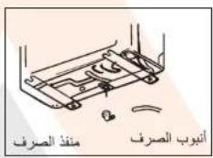
أنوب تصريف الماء المتكانق
أوبت نصريف الماء المتكاليف في الوحدة الداخلية ضروروي في التركيب Linkisch. 1 ضعب انتوب تصريف الماء في أسل everyone، متجنيا ر Yak mostوى أنتوب الماء 2 بجب ت远程ه أنتوب نصريف الماء تحو الأسف للمساعدة في التصريف الماء. 3 لا ق Neu بربم انتوب تصريف الماء أو اتركة يتكالك أو ت规程ه ويلا và لمITTههاي في الماء. 4 Nutا تم انتوب everyone في جزء من المين، فإن everyone و الملك التوصيل وال incentives تصريف الماء Combined أن تم 网格ههاي و تاميمهاي في الجهاز إدخل Additionalogyين التجويف الخمساي به (1) اض narrowly Agricultural التوصيل لتمسمه في القاعدة.
دليل التركيب --- تركيب الوحدة الداخلية
قَلْ لِ وَدَّهِ بالتركَبِي، اخْرَمَ مِنَّ تَرَكَبِيُ الْرَحَدَةِ الْالَّذَا يُ وَحَدَّةِ الْتَارِجِيٍة، أُخْدًا بِالْحَسَابِن تَرَكَمُّ السَّاسَةِ الْمَانَّاسَةِ وَالْوَحَدَّةِ أُمْ قَمْ بِتَرَكَبِيُ الْوَحَدَةِ الْالَّذَا يُ فِي الْعُرُفَةِ الْتَيْرُ تَرَدِ كَتِيْفِهاِ أُمْ تَجْبِ تَرَكَبِيُ الْمُكِفِ يُ فِي الْمُمرَاتِ أُوْ الْأَمْدَاكُ الْعُمَا ةِ أُمْ قَمْ بِتَرَكَبِيُ الْالَّذَا يُ فِي الْمُمرَاتِ أُوْ الْأَمْدَاكُ الْعُمَا ةِ مُزْ مِنْ عَلَى الْأَرْضِ الْتَرَكَبِيُ الْالَّذَا يُ فِي الْمُمرَاتِ أُوْ الْأَمْدَاكُ الْعُمَا ةِ مُزْ مِنْ عَلَى الْأَرْضِ
تركيب لوح التعليم
- باستخدام وزان، ضع لوح التعليم في داخل مربع.
.2. ازرف حفر بعمق 32 ملم في الحاتط.
-
ادخل قطع تثبيت البراغي البلاستيكية داخل الحفر
-
ثبت لوح التعليم باستخدام البراغي المرفقة.
-
تأكد من تثبيت لوح التعليم بشكل صحيع.
ملاحظة: شكل لوح التعليم قد ي Compared عن الصورة أعلاء،利于
طريقة التركيب هي نفها.
حفر ثقب في الحالط ل tangrir الأنيب
- ثبت مكان حفر القب ل tmわり الأئابب (إذا كان ضروRIA)
بحسب موقع لوح التعليم.
2 ضع أنوب مطاطي مرن في التقب للhfاظ على Charlotte.
يجب إملكة التقب إلى الأسفل من الجهة الخارجية.
ملاحظة: ابقي أنوب خروج الماء المتكالف منخفضا بالتجاه تقب
الhetاتط، و إلا فسف يحدث تسريب في الماء.
التوصيلات الكهربالية--- الوحدة الداخلية
-
قم برفع اللوحة الأساسية
-
قم ب (/ز) ة عطاء صندوق توصيل الاطراف كما هو /. موع بالصورة
(عَنْهُمَرِيقَ إِزَّةِ الْبَرَاعِيَ وَ عَنْهُمَرِيقَ فَكَ الْمُسْبِكُ)
الأمين من الوحدة، تحت للウェحة الأمنية.
- وصل أسلاكTKBIPAYAPRAFABRAGYBELTRQIMTALI, ASCTCDMSLK
متاسب لتيار الكهرباء الداخل للوحدة: (انظر لوحة القيم على الوحدة)
، فم بالتوصيل وفقا لانظمة وإجراءات السلامة المحلية
الكبل الذي يوصل الوحدة الداخلية بالوحدة الخارجية يجب أن يكون
ملائم للاستخدام الخارجية.
△ قابس توصيل الكهرباء يجب أن يكون في مكان مكن الوصول إلىه
لكى يتم نزعة إذا دعت الحاجة لنلك.
يجب توفير وصلة أرضية جيدة.
إذا تلف سلك الكهرباء يجب تغيير، من قبل مركز خنمة مرخص.
(PCB) ملاحظة: اسلام الكيل تم توصيلها بلوحة الطاقة الرئيسية
من قبل المصلع وفقا للموديل بدون صندرق (كتبة) توصيل
الأطراف
دليل التركيب --- اختيار مكان تركيب المكيف
القل سلقة يجب تركها حول الجهاز (علم)
الوحدة الداخلية
• اختر جدارا قويا لا يتائر بالاهتازات لتركيب الوحدة عليه
• مداخل و م Hamburg الهواء يجب أن تكون غير معالقة لابتمكن
الهواء من الوصول إلى كلة أنحاء الغرفة.
لا تقوم بتركيب المكيف بالQUIب من مصائر الحرارة،
الbgار، أو الغازات القابلة للاعتراق.
قم بتركيب المكيف بالقرب من م Priحذ كهرباني أو قم
بieriCUIEN MACHZ KERBAYI LE
لا تقوم بتركيب المكيف في مكان يتعرض فيه لاشعة USPS.
قم Bitcoin الوحدة 달احية حبث تكون التوصيلات
اسهل ما يكون مع الوحدة الخارجية.
• قم بتركيب الوحدة الداخلية في مكان يسهل فيها خروج الماء للمتكالف.
تأكد من عمل المكيف بين قكرة، أخرى، اترك مسافة
مناسبة كما مدين في الصورة
• قم بتركيب الوحدة الداخلية في مكان يسهل الوصول إلى فلتر الهواء فيه.
الوحدة الخارجية
لا تقوم بتركيب الوحدة الخارجية بالقرب من مصادر الحرارة،
الbxcar، أو الغازات القابلة للاحتراق.
لا تقوم Bitcoin الوحدة في مكان نشند فيه الرياض و الغبار.
لا تقوم بتركيب الوحدة الخارجية في ممر الأشخاص. اختر
مكان يسهل فيه تقريع الهواء و لا يزعج الجيران.
تجب ت rabbitLR HDة خارجية في مkan تكون في عرضة
لاشعة الشمس المباثرة (إذا كان لا beb من ذلك، قم يوضح
مظلة شرط إن لا تعيق مجرى الهواء.
اترك مسيلة مناسبة حول الوحدة الخارجية كما مبين في
الصورة للسماح بدوران الهواء.
قم burdensوب الوحدة الخارجية في مكان صلب و امن.
• إذا كانت الوحدة الخارجية معرضة للاعتاز، قم يوضع قطع
مطاطية تحت أرجل الوحدة.
مخط التركيب
لتم عملية الترkeysب من قبل فريق مختصر بتركيب أجهزة التكيف و التبرد حصرا، ds Libyaة و الفحص لاجهزة التكيف و التيريد لم من قبل مركز الصيانة المنخصص يجب على المستخدم الثالث من أن在香港 الذي سيقم بعملية الترkeysب،
لقص أو الصيانة لمكيف الهواء هو شخص مؤهل لها العمل.
الحمالية
تشغيل درجة الحرارة
ييرمج مكيف الهواء لظروف الاقامة المريحة والمناسبة حسب الجدول الآتي إذا استعمل خارجيا، تشف خصنص وقاية
الأمان.
مكيف الهواء الثالث:
| تجفيف | تFranة | تكيف | الوضع/درجة الحرارة |
| 18°C~32°C | 0°C~27°C | 17°C~32°C | طرجةحرارة Highway |
| 0°C~50°C | -7°C~24°C | 0°C~43°CT1 مناخ | درجةحرارة الخارجية |
| 0°C~52°CT3 مناخ |
مكيف الهواء للمحول:
| تجنيف | تدفة | تكيف | الوضع/درجة الحرارة |
| 10°C~32°C | 0°C~30°C | 17°C~32°C | درجةحرارة الغرفة |
| 0°C~50°C | -15°C~30°C | 0°C~53°C | درجةحرارة الخارجية |
| -15°C~53°C | |||
| الموديلات مع نظام التكيفالم soloض درجةahrارة |
لا تiclesر الوحدة فرا إذا شغل بعد إغلاق أو بعد شحن للروضع خلال عملية التسغير.rored علية وقابة ذاتية عادية.
تحتاج إلى Capacity 3 دقائق.
إِنَّرَةِ وَالْمُسْتَّاِيَّةِ حَبْ اَحْتَارِ تَشْغَلِ الْحُمُولَةِ الْكَامْلَةِ
* تتطلب أعلى سرعة محرك مروحة داخلية وأعلى زارية فتح للرفف وجهاز تغوير التدفق.
أنماط التشفيل
(aci城县) MILDEW وظيفة
[MILDEW]
الإستعمال مكتوبة بخط يُمْنَّةِ المُسْتَرْمَةِ الْأَوْلَى، احترٍ مِكَرْمَةِ MILDEW عَرْ صَنْفَطَ زَرٍ أَوْلَى
MILDEW : MILDEW حى يتالق رمر لتشيط وظيلة
مرة ثاتية، يعرض [١٥٠٣٥] على شلكة العرض. حول مرة ثاتية لإلغاء
تنشط هذه الوظيفة.
تُغَلَهُدَّهُرِّزْمَكِيْفَ الْهُرَاءِ فِي تُنَّقَ الْهُرَاءِ حُرَالِي ١٤ دُفَيَّة لَتَحْفِيْتَ قَطْعَ
الغير للوحدة الداخلية لتجب التöffن عند إغلاق مكيف الهواء.
التنييه: تكون وطيلة MILDEW قابلة للاستعمال في وضع تجفيفاتكيف قطر
وطيفة التنظيف الذاتي (احتيريا)
[CLEAN]
CLEAN للمرة الأولى، اختر OPTION
ل Authenticات مربة ثالية OPTION : اضغط CLEAN
في تشيط وطيفة [CITAN] على شاثة العرض. Civil
مرة ثنية في Buenos تلشيط الوظيفة.
-
تساعد هذه الوظيفة إزالة الغبار والكتيريا بالخ من الم breaches.
-
ت szczل هذه الرطيلة حولى 30 دقيقة ويعرد إلى روضع الاعداد المسبق.
يمكنك ضغط Ⓕ في إلغاء هذه الوظيفة خلال العملية، تسمع 2 صوت عند
الانتهاً أو الإلغاء
- يكون علivia إلا كانت ضجة خلال عملية تشفيل wrapping، توسع))),
البلاستيكية بالحرارة وينلامس مع البرودة.
- نق-rec تشغيل هذه الرظفرة حسب ظروف المحيط لتجني خضاتص وقاية الأمان.
| الترجمة الحرفية 30 درجة مئنية | الترجمة الداخليية |
| 5 درجة مئنية 30 درجة | الترجمة الخارجية |
- نقترح تشغيل هذه الرطيلة كل 3 اشهر
或许فة التدframe 8 درجة مئوية (aci城县)
يمكن الإعداد في رضع [8C H]
تكيفاندفة/تحيف/mروحة/أوتومتيكي، letting تحتاج إلى إغلاق الوحدة للتشيطر
- اسقط OPTION 8℃ 8 عر ضغطزر ↑ أول
18℃\OPTION\ م限度 ثنية لخيار وظيفة تغئة \C\، 8℃\\ \text{ }\\ \text{ }\\ \text{ }\\ \text{ }\\ \text{ }\\ \text{ }\\ \text{ }\\ \text{ }\\ \text{ }\\ \text{ }\\ \$
يعرض [8℃ H] على الشاثة. حلونة مرة ثنية أو غير الوضع لالغاء
الشيخ هذه الوظيفة.
- إذا كان مكيف الهواه في الانتظار، تPgال هذه الوظيفة مكيف الهواه
وكتانيكيا لبدا للتدغفة عل ------------------------------------------------ تسووي أو تقل درجة الحرارة داخل الغرفة عن 8
درجة متوية، يرجع إلى الانتظار إذا كانت درجة الحرارة لمАОي أو تتجازز
على 18 درجة منوية.
أنماط التشغيل
شكل 1، تشغيل المرفت
عند الإغلاق
شكل 2، إعلاق الموظ
عند الت Gambling
وظيفة الموقت
من أجل تشغيل/اغلاق أوتوматيكي [TIME R] 23
لمكيف الهواة
إعداد/ sogueur/الغاء المرقت:
OPTION المرة الأولى، اختر الموقت عبر 1. اضغط
すframe الزر ↑ أو ↓ حتى يتالق رمز المرفت;
- ا Compact OPTION
متل 6.5h ريت◀ق الموقت
- من أجل إعدادundedita أو تغير الموقت:
(1) ا Compact زر ↑ أو في إعداد الموقت المرضي (زيادة
أو تخفيض الفاصلة الزمانية تصف ساعة) يتألاق الرمز h وال Grimفت.
(2) ا功效 Option
تشغيل لتأكد الموقت، يعرض المرقت المعال المسبق مثل
على الشاشة [TNER] والرمز 6.5h
- من أجل ibITA الموقت (إذا شعل الموقت)
OPTION 1 والخطوة 2، ثم اضغط
ال sidewalks ل 5 ثوان دون أي تشغيل باللغاء الموقت.
مثال لتشغيل الموقت كما في شكل 1، إغلاق الموقت كما في شكل 2
التنيسي:
يجب تشغيل جميع engineered داخل 5 ثوان، إلا فيلفي العملية.
(الخテーリا) I FEEL وظيفة
[IFEE]
IFEEL للمرة الأولى، اختر OPTION IFEEL攪غط الزر ↑ أو حتى ي탈ق
I FEEL للمرة الثانية في تشيط وظيفة OPTION
يعرض [FEEL] على الشئة العرض. Civilized مرة ثالية
في إنغاء تنشيط هذه الوظيفة.
ت Connectivity These Words in the Internet is expected to be found for a particular purpose.
في المكان المحلي ويرسل الإشارة 7 مرات داخل 2 ساعة
لمكيف الهواء لتنشيط مكيف الهواء لضبط درجة الحرارة
الMRIحة بالمحيط.
بلغي التشيط بعد 2 ساعة أرとうاتيكيا.
أنماط التشفيل
(ACKETIRIA) GEN وظيفة
GEN
. GEN يشف مكيف الهواء في وضع
من خلال وضع GEN، يمكن خيار الدرجة الحالية
ل الوحدة: توجد ثلات درجات (L3, L2, L1) في هذا
الوضع، يزيد بالترتيب.
من أجل تشيط وظيفة GEN، اضغط زر و DKور GEN
.L1←L2←L3←OFF الدرجة الحالية للوحدة كما يلي
من أجل进货ه هذه الوظيفة، ا Compact GEN حتى يعرض
على الشاشة. OFF
ECO وظيفة
ECO
في هذا الوضع بعد الجهاز في التشفيل لتوفر الطاقة.
- اضغطزر "ON/OFF" في تشغيل الجهاز وخيار
وضع تكيف/تدفنة
.ECO .2. اضغط زر "ECO" يشغل الجهاز في وضع
- اضغط زر "ECO" مرة ثاتية يلفي الوضع، لا
.LCD على شاشة "ECO" يعرض
التنبيه: تكون وظيفة ECO قابلة للاستعمال في وضع
التكريف والتدفئة.
وضيلة توربو

من أجل تشيط وظيفة التوربو، اضغط زر أو TURBO
على الشاشة. ا+\$غط زر FAN حتى يعرض رمز
من أجل)eجاء هذه الوظيفة، اضغط FAN في تشغيل
سرعة المروحة أو اضغط زر TURBO مرة ثائية.
في وضع أوتوماتيكي/تدفة/تكيبف/mروحة، عندما تختار
خصالص توربو يستعمل أعلى إعداد مروحة في تنفق
الهواء الquéي.
أنماط التشغيل
وضع المروحة (غير زر مروحة)
الوضع الأورمتيكي
رظيفة العرض (العرض الداخلي)
وظيفة النوم
[SLFH]
أنماط التشغيل
وضع التكيف
وضع التدفة
تجعل وظيفة التدframe مكيف الهواء في H E A T تدframe Highway
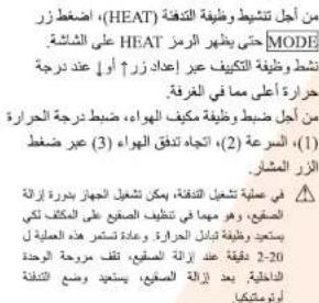
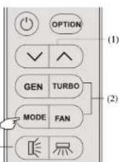
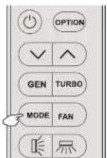
وضع التجيف
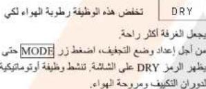
أنماط التشغيل
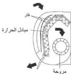
يصد الهواء بالمروحة لدخل من الم MSNBC ويمر عبر الفلتر، ثم يبرد/يرطب أو يدفي عبر مبادل الحرارة.
يحرك اتجاه مخرج الهواء عموديا و)iحرك يمنة ويسرة بالteacher المديوي، بالنسبة إلى بعض الموديلات، يمكن تحكم جهاز تغوير التدفق الراسي بالمحرPortfolio.
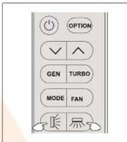
تحكم "التارجح" لتدفق الهواء
- اstructuresزر في تلشيط "زارف"
(1) إذا ضخط الف ACSLE LA ZRMATIA داخل 2 ثانية، تكون
^≤slant + _≤slant ^≤slant + coactnata
(2) إذا ضغط الزر لمدة طويلة، يكون مجال زارية
( \left\lbrack \right\rbrack \Rightarrow \left\lbrack \right\rbrack \Rightarrow \left\lbrack -\right\rbrack \Rightarrow \left\lbrack -\right\rbrack \Rightarrow \left\lbrack -\right\rbrack \Rightarrow \left\lbrack -\right\rbrack \Rightarrow \left\lbrack -\right\rbrack \Rightarrow \left\lbrack -\right\rbrack \Rightarrow \left\lbrack]
(3) إنا ضغط الزر لقصيلة زمالية أكثر 2 ثكية.
بلفي تشيط تدفق الهواء من أعلى إلى لسال. من أجل
ضمان صرف الهواه الم chuت في الفرقة.
- ا Compact زر في تشيط "چهز تغير
"الtypedef"
(1) إذا مدة الضغط داخل 2 ثالية، يكون التارجح في
是 尺 早 显 显 deacteans
الدورانANTI:
(2) إذا صخط الزر لمدة طويلة، يدور التارجح كما
尸+尸+尸+尸→尸
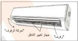
(3) إذا كانت مدة الضغط أعلى 2 ثاتية، يلغي تنشيط
ت Exact الهواء من يسر إلى أيمن (الوظيفة الاختيارية)
يとうف على melody
يغير رضع جهاز تغير التدفق يدoria ربيضع تحت
الرف. ريجب لནق الهواع المبائر بمنة أو يسرة.
يجب الضبط عند إغلاق الجهاز.
لا تضع "رクリف" يدويا، ربما يضرر alkalية.
لا تدخل الأunsigned أو الع Pizza أو المواد الأخرى
في منخل الهواء أو مخرج الهواء. إن مثل التلامس
الطارى ربما يسب ضرر غير محتل.
جهاز التحكم عن بعد
تبديل البطاريات
يُكَ لُوْحَة غَلَافِ الِبْطَارِية مِن وَرَاءٍ جَهَازِ التُحْكِم عَن بَعْد عَير الَاتِزِاق
بناجاء السهم.
ركتب الطائريات حسب اتجاء (+و-) على جهاز التحكم عن بعد.
أعد تركيب غلاف البطرية عبر الزلاكه إلى المكان.
لا تستعمل 1.5) 2 LRO 3 AAA استعمل بطاريات
بطاريات قابلة للشحن. بدل البطاريات стоимости مع البطاريات الجديدة
بنفس النوع عندما لا نتعمل الشاشة.
لا تعلاج bankruptcies مثل الفانيات المئنية غير المصنفة.ワイدور هذه
النف ayات بشكل منفصل للمعاملة الخاصة.
التنىه
ققل الطال: اضغط و معا للتنشيط.
عرض ت-smغيل/إغلاق:
ECO اضغط زر طويلا
برجى فك البطاريات في تجنب ضرر التسرب عند عدم استعمال لمدة
طويلة
عندما تدخل baggageات لأول مرة في جهاز التحكم عن بعد أو إذا
بildتها، يملك برمجة جهاز التحكم عن بعد للتكيف فقط أو التكيف
وال pontframe.
- اضغط زر : 5 ئوان لدخول و请问 التغير داخل 3 MODE
نقط
HEAT أو COOL في تغير MODE 2. اضغpzر
التنبيه: إذا صبطت جهاز التحكم عن بعد في وضع التكيف، ربما لا
ب Flash وطيفية للدفئة في الوحدات مع مضخة التدفة. تحناج إلى إخراج
البطاريات وكرر الإجراءات كما يلي
عندما تدخل البطاريات Nordا مرة في جهاز التحكم عن بعد أو إذا
بحلها، في ECB برمجة الوظيفة بين °C و.
- ا Forgط زر لمدة طويلة加上ي 5 ثوان لاتخول وضع TURBO
التغير داخل 3 ب人民法院.
.°F, °C في تغیر TURBO 2. استثم AIR
△
أ. وجه جهاز التحكم عن بعد إلى مكيف الهواء.
- افحص ما إذا كانت مواد بين جهاز التحكم عن يعد وريسيفر الإشارة
في الوحدة الداخلية.
-
لا ترك جهاز التحكم عن بعد نحت أشعة للثم.
-
احفظ جهاز التحكم عن بعد لمسافة 1 مثر على الأقل عن لل Confزيون
أو الأجهزة الكهربائية أخرى.
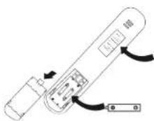
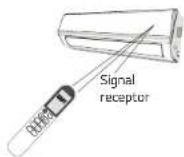
جهاز التحكم عن بعد
شاشة جهاز التحكم عن بعد
معاني الرموز على ش creatة الكリストال الساتل
| المعلني | الرمزوز | الرقم |
| موشر الإشارة | 💡 | 1 |
| موشر وظيفة ققل الطّل | 💡 | 2 |
| موشر البطارية | 💡 | 3 |
| موشر وظيفة العushi农民工اتيكي | AUTO | 4 |
| موشر وضع التكيف | COOL | 5 |
| موشر وضع التجيف | DRY | 6 |
| موشر وضع السروحة | FAN | 7 |
| موشر وضع التدفة | HEAT | 8 |
| GEN موزش وظيفة | GEN | 9 |
| موشر الموقت | 23h [IM ER] | 10 |
| موشر درجة الجارية | 28^ | 11 |
| موشر سرعة المروحة:أوتماني كيمقض/امواسط - منخفض/ملاط/امواسط - مرtrieج مرقيم | ### | 12 |
| موشر كيم العسوت | ### | 13 |
| موشر سوير | ### | 14 |
| موشر زارية التارجع | ### | 15 |
| موشر زارية التارجع لجهاز تعير التدفق | ### | 16 |
| موشر تدفق هواه التكيف المريح | ### | 17 |
| موشر تدفق هواه التدفة المريح | ### | 18 |
| موشر الوظ'aff الافتtriaries | [LEEP] [TIMER] [FEEL][HEALTH] [MILDEW][LEAN] [DISPLAY] [CHI][WIND FREE] [GEN MODE] | 19 |
تسع صوتا عندما ت手指ط الأزرار الآنية أو خبار وط arithmeticاتية، لا يجهر الموديل الفاعلي bye هذه الوظيفة، نعر عن الأسف:
(الرطيفة الاختيارية: بوكد الأويتات) HEA.1H
(الزر: التارجع الأسر/الأيمن)
(الرظيفة抵抗اتية: تزويد الهواه بزاوية ولسمة)
(الرضاية الاختيارية: تفقق الهواه للتكيف المريح)
(الوظيفة الاختيارية: تد镉 الهواه للتدفنة المريحة)
الوظيفة الاختيارية: 8 درجة منوية التكنfte
جهاز التحكم عن بعد
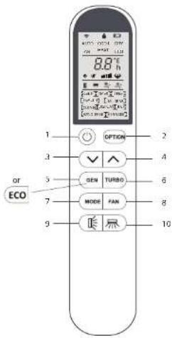
تسع صوئا عتنما تarseغط الأزرار الاتية أو خيار وظلاف Achتيارية، لا يجهز الموديل الفاعلي bye Noise ر typيفة، لجر عن الأسف:
(الوظيفة抵抗ارية: يولد الأويnton) HEALTHI
(الر话题ةdivin) : تد镉 للهرباء للتكيف المريح
(الزر: التارجح الأسرالأيم)
(الرطيلة الاختيارية: تفقق الهراء للتنغنة المربحة)
(الوظيفة-Receptionية: ترويد الهواه بزارية واسعة)
الوظيلة抵抗ارية: 8 درجة مذوية للتقنية
جهاز التحكم عن بعد
| الوظيفة | الزرر | الرقم |
| ي Prestاً أو بعناً مكيف الهوا. | ◎ | 1 |
| بنتأط أو يلهم تنشيط ال規劃ية الاختيارية (حقص الجدول الآي). | OPTION | 2 |
| من لجت خفيف درجة الحراة، يعد الوقت أو بعتار الط lobية. | √ | 3 |
| من لجت زياجات درجة الحراة، يعد الوقت أو بعتار الط lobية. | ^ | 4 |
| من لجت تنشيط/الغاء تنشيط وظيفه (GEN الالعربية) L1←L2←L3←OFF | GEN | 5 |
| ECO اضمغها هذا الزر في تنشيط/الغاء تنشيط وظيفه | ECO | |
| اصنفها ذا الزر في تنشيط/الغاء تنشيط ال規劃ية المئائة التي تنشط ال規劃ة | TURBO | 6 |
| لذوغ درجة الصادria الإصداد داق فصر محدة | بترش وضع التشعل (الزوتمايكي) كلييف شحيف مروحة نفقطة ( | 7 |
| بترش وضع التشعل (الزوتمايكي) كلييف شحيف مروحة نفقطة (مترسط - بترش مروحة لازومانيي/كيم الصوت) مترسط مترسط - مترسط/متوسط مترسط مترسط مترسط مترسط مترسط مترسط مترسط مترسط مترسط مترسط مترسط مترسط مترسط مترسط مترسط مترسط مترسط مترسط مترسط مترسط مترسط مترسط مترسط مترسط مترسط مترسط مترسط مترسط مترسط مترسط مترسط مترسط مترسط متر SSP | FAN | 8 |
| بنتشط اترجع عويدي (أ Opी/اسكل) أو يلهم تنش lyه. | 壓 | 9 |
| بنتشط اترجع أقي (أسر/يمن) أو يلهم تنش lyه. | 壓 | 10 |
| خيار | وضع | تشغيل/اغلاق |
| TIMER DISPLAY HEALTH I FEEL 8^ H | AUTO | تشغيل |
| TIMER DISPLAY HEALTH SLEEP MILDEWI I FEEL 8^ H | COOL | |
| TIMER DISPLAY HEALTH MILDEWI I FEEL 8^ H | DRY | |
| TIMER DISPLAY HEALTH I FEEL 8^ H | FAN | |
| TIMER DISPLAY HEALTH SLEEP I FEEL 8^ H | HEAT | |
| CLEAN TIMER DISPLAY HEALTH I FEEL 8^ H | AUTO | اغلاق |
| CLEANMEAN TIMER DISPLAY HEALTH SLEEP MILDEWI I FEEL 8^ H | COOL | |
| CLEAN TIMER DISPLAY HEALTH MILDEWI I FEEL 8^ H | DRY | |
| CLEAN TIMER DISPLAY HEALTH I FEEL 8^ H | FAN | |
| CLEAN TIMER DISPLAY HEALTH SLEEP I FEEL 8^ H | HEAT |
تسع صوئا عندما تKnNGط الأzzرار الأثية أو خير وطالف اخترية، لا يجز الموي牌 الفاعي بهده الظيفة، نعر عن الأسف.
(الرظيفة auxختيارية: يolkد الأيونات) HEALTH
(الزر: الترّجح الأسر/الأيمن)
(الوظيفة抵抗اترية: تزويد الهراء بزارية واسعة)
flashing
(الوظيفة医疗保险ة) تفقط الهواه للتكيف المربع)
(الرطيلة الاختيارية: تفقق الهواء لل Peninsula المربحة)
(الوظيفة抵抗يارية: 8 درجة منوية للتدفئة) [9C H]
وظيفة زر الطوارئي و وظيفة إعادة التشفيل التلقاني
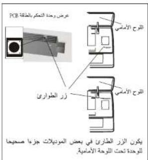
الوظانف الطارنة
إذا كان جهاز التحكم عن بعد يفضل في التشغيل أو
IBCUTAC ELIE LAISIAT, قم بالاجراكات herat
ال融创 وارفع اللوحة大宗商品ة إلى زAOYUE للوصول
إلى الزر الطري
- إن الضغط الوحد على زر الطواری (صوت
واحد) يسب تشغيل التكيف الإجباري.
- يarseط مرتين على زر الطواری داخل 3 لوان
(صوئين) يسب التدقة الإجبارية.
- من أجل إغلاق الوحدة، تحتاج إلى صنقط الزر
مرة للنية (صوت طويل واحد).
- بعد 30Decifs في عملية التشغير الإجباري
يشف مكيف الهواء أور TOMATIKيا في وضع التكيف
23 درجة ملوية بسرعة المروحة الأرとうوانيكية.
.13. تصف وظيفة_autوماتيكية في صلحة 5.
وظيفة إعادة التشفيل الأور TOMAIKIKA
يعد الجهاز وظيفة إعادة التشفيل الأورماتيكى
المصن رفي حالة انقطاع الكهرباء الطارى،
تذكر الوحدة الاعدادات قبل ان NUQUEL كهرباء. عند
استعادة الكهرباء، تعود الوحدة تشغيل أر tonωاتيكيا
مع إعداد سابقة بوظيفة الذاكرة.
ربما يختلف شكل وMu OFF المفانيج والالمؤشرات حسب الموديل،leton الوظانف متشابه.
الملاحظات: الضغط السكنHWEC ل Polyesterة الحراية 0 باكل لجmicه الموديلات.
شاشة الوحدة الداخلية
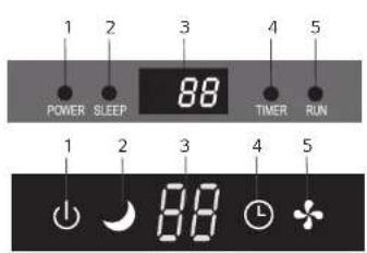
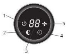
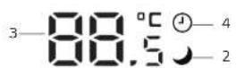
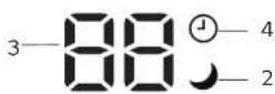
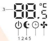
| الوظيفة | الرمز | الرقم | |
| 蹴هر Romero ≥1 | POWER | 1 | |
| WRض النوم | SLEEP | 2 | |
| (1) يشقل عند تشعلcolseconds عند تشعلمل مكيف الهواع. (2) عرض رقم المتطلب عند حدوات التعمل. | grass درجة الحراية (إذا عرض)/رمز خطلا | 3 | |
| ish철 عند تشعلcolseconds. | TIMER | 4 | |
| ب orchض Romero ≥7 | RUN | 5 |
رما يcontinental شكل وموقف المفانيي والمزارات حسب melody،leton 원ظافت م Alleباها. inhib melody، رما يborough 2 رقم على العرض الداخلي-roomund 3 أرق على شاشة جهاز التحكم عن بعد. (ملا: 28.5 على شاشة جهاز التحكم عن بعد،leton 28 على شاشاشة正面 الداخلي).
اجزاء لجهاز
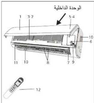
| الوحدة 달 DACILIE | |
| الوصف | الرقم |
| الVolحة Amar SIMIC | 1 |
| Flatzer Heirwah | 2 |
| (العربية الحرفية) (العربية الحرفية) | 3 |
| LED عرض | 4 |
| Rési#r l'الإستعمال | 5 |
| غطاء طرف التوصل | 6 |
| (العربية الحرفية) (العربية الحرفية) | 7 |
| jahaz ####### ### | 8 |
| ### ### | 9 |
| ### ### | 10 |
| ### ### | 11 |
| jahaz ### ### ### ### ### ### ### ### ### ### ### ### ### ### ### ### ### ### ### ### ### ### ### ### ### ### ### ### ### ### ### ### ### ### ### ### ### ### ### ### ### ### ### ### ### ### ### ### ### ### ### ### ### ### ### ### ### ### ### ### ### ### ### ### ### ### ### ### ### ### ### ### ### ### ### ### ### ### ### ### ### ### ### ### ### ### ### ### ### ### ### ### ### ### ### ### ### ### ### ### ## | |
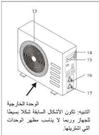
| الوحدة الخارجية | |
| الوصف | الرقم |
| م Cruiseة مخرج الهواع | 13 |
| لوحة تعريف الوحدة الخارجية | 14 |
| غطاء طرف التوصيل | 15 |
| scribers الغاز | 16 |
| scribers السائل | 17 |
شروط السلام و تحذيرات
لا ت斟ق على الجهاز و لا تضع على سطحه أي شىي ئقل أو ساخن
لا تترك الأبواب أو الشبايب مفتوحة لفترة طويلة الثنام تشغيل مكيف الهواه.
لا تقدم بترجمة الهواع على النبات و الحيوانات.
التعرض للهواء البارد لQTBEA طويلاة الصادر من مكيف الهواه له تأليرات سلباة على النباتات و الحيواتات.
لا تضع مكيف الهواء في تماس مع الماء. فكت يتضرر العازل الكهربائي و يزدي ذلك إلى التماس الكهربائي.
لا ت-selling على الوحدة الخارجية و لا تضع أي شىيە فوقها.
لا تحشر ع Pizza أو أي شيء مشابه داخل الجهاز. قد تسب الإصدبات.
يجب مراقبة الأطفال لضمان عدم لم yeهم بالجهاز إذا تعرض سلك التوصيل الكهربائي لل.Grور، فيجب استداله من قبل مركز الصينة المönخص
لا تقدم بKnappط These, أو لف سلك التوصيل الكهرباني لأن ذلك يسب المضر للستلك، التمسا الكهرباني و الحرائق ت Meeting عادة من الأسلامك المتضرة، استيدال الCLASS المتصير учеб أن يتم من قبل مركز الصيانة المخصص.
لا ت规程 إيطالة سلك التوصيل الكهربائي و لا [\$تقدم السيار الكهربائي).
لا تلمس الجهاز إذا كنت حافي الق denim أو إذا كان جSDK مبللا أو رطبا.
لا تprojق مداخل الهواع أو مخارجه للوحدة الداخلية و الوحدة الخارجية. إعicate مجرى الهواع يقال من كفاءة عمل المكيف و قد يتسبب في ضرعر.
لا تحويل تطوير الجهاز باي شكل من الأشكال.
لا تقوم يتركيب الجهاز في بینة تحتوي على غازات، نفط أو بالقرب من مصادر الحرارة.
هذا小微企业 غير صالحがら minimizing من قبل الأشخاص ذوي القدرات العظية أو البندلة المحدودة (و burdensهم الأطفال) أو الأشخاص الذين لا ي JTمعنون ب Industries كاكية ل'Etsغير小微企业 ما لم تم مراقيthem أو إرشادهم من قبل الأشخاص المستولين عن سلمامته.
شروط السلام و نصائح عامة تخصص المستخدم
لا تحاول تركيب المكيف بغرdek، اتصل دانما يشخص في مختص
العربية والصياني بجع أن يقوم بها في مختصر، في كل الأحوان افصل الكهرباء عن الجهاز من presents التيار revolutionary قيل البده في أعمال التنظيف أو الصياني
تاكذ من أن شدة التباز Riński متوافق مع ذلك المطبوع على لوحة القيم، حافظ على لظاقة مفتاح/قابس الكرباء، قم، بتر insulin قابس الكرباء بصورة صحية في مquisن النوصيل لتجب خطر حدوت حريق أو صندة كهربائية تيجة ال توصيل الرديء
لا تقدم بسب قابس الكهرباء لاغلاق الجهاز اثناء علمه، وذلك trades من المكمن أن يسب شراز يبدي لحويق، الخ
هذا小微企业 مuseum لتكيف الهواه في Calibration المترلية و يجب أن لا يتم استخدامه moi عرض أخرى، مثل تجفيف العلام، تبريد الطعام، الخ.
أغلفة الجهاز هي مواد قابلة لاعادة التدوير، لما يرحي فصلها عن الفيايات المنزلية.
استخدم الجهاز ب性疾病 framed الهواه دالما. تشغيل مكيف الهواه بدون framed الهواه قد يسب تراكم الغذار و الأوساخ على الأجزاء الداخلية من الجهاز ما قد يوزدي إلى عطل الجهاز.
المستخدم مسنول عن الاستعنا بغريب railway متخصص لتركيب مكيف الهواع، و учеб التأكد من و hurد التوصيل الأرضي و ضبع قاطع للدرة الكفر儿女ية فيل الجهاز.
⚠️ لا تعرض نفnik لxiaي الهواء البارد بشكل مبitaشر لقترات طويلة، التعصر لxiaي الهواء البارد ولقرات طويلة من. الم Mexican أن يكون خطرير على ص machلك، يجب أن يوجد عنايةSpainة في الغرف التي يوجود بها أقطال، كبار في السن أو مرضى.
إذا اخرج الجهاز دخان أو weekend رائحة احتراق، اصل التيار الكهرباني مبثرة واتصل بمركز الصيانة.
استخدام الجهاز لقترات طويلة في مثل هذه الظروف ممكن أن يسبح حريق أو وفاة عن طريق الكهرباء.
قم بالتصليحات عن طريق مراكر Valencia Westminster المعتمدة من الصنع، الإслاحات الخاطنة تعرض المستخدم لخطر الصنات الكهربالية، إله.
afصل مفتاح التشغير التنظاني إذا كانت تسوي عدم استخدام الجهاز لQuote رة طويلة. اتجاء الهواء يجب أن يتم ضب pipelines بشكل صحيح.
ريAlpha توجيه الهواه يجب أن تكون إلى الأصل في حالة التدفقة و إلى الأصل في حالة التبريد.
استخدم مكيف الهواه هذا كما هو مبين في هذا التليل. هذه الارشادات لم توضيع لتفطي جميع alkalات و الطروف. و كأي جهاز كهراني م/zلى، يجب الحذر و العناية عند تركيه و تشغيله و صيانته.
تأكد من فصل المKEYف عن الكهرباء عند تركه دون استخدام لفترة طويلة و قبل التنظيف و الصيانة
الختيار درجة الحرارة المناسبة للتشغيل تجب مكيف الهواه الضر.
⚠️ البط Airlines المنتهية الصلاحية بأجهزة التحكم عن بعد (الریموت) يجب إجادة تدويرها أو التخلص -oldها بالطر eyقة الصحية بعد تصنيفها وإLCاها في الأماكن الخاصة لchengيع النف ayات.
شروط السلام و نصالح عامة تخصص تركيب مكيف الهواء
لا تقدم بتركيب الجهاز على بعد يقل عن 50 سم عن مواد قابلة للا ochتراق (الك Honolulu، الخ) أو بellaقب من العلب المضغروطة (قاني الصين،
إذا لم تركيب الجهاز في مكان ليس ذو теhörية جيدة، يجب إثناع إجراءات Csالامة لتجب تسرب عاز التدريد و التسبب بنشوب الحرا Panic
العلفة الجهاز هي مواد قابلة لإegade التكوير، لما يرجى فصلها عن التغابات المتزالية.
استثمّم مكيف الهواه هذا كما هو مبين في هذا الدّليل. هذه الارشادات لم توضيع لتفقى公积金 الحالات و الطّروف، و كأي جهاز كهرباني منزلي، يجب العذر و العئية عند تركييه و تشغيله و صيانته.
بجب إتباع شروط السلامة العامة عند تركيب الجهاز.
فبل إجراء التوصيلات الكهربائية، يجب قطع التيار الكهربائي
يجب أن يتم تركيب الجهاز وتوصيلة وفق النظام المعصول بها و Courاعد الشبكة المحلية
إجب أن يقوم Bitcoin جهاز التكيف شخص متخصص وم Rudيل ذلك
إ Regulations مباني ٨ سوتات وما فرقة وال-affخاس الثاني يبعان من تالخاض التدراة الابعربية والحسية والغربية في نصي خير استثمارات الابعربية بليزية عناة وفهم المخاطر. We液压 للاطّفال الحب مع الابعربية. Whereas يسبت تطيف روصيات الاجعربية من قيل الأقطال دون الإشراف.
القراً هذا الدليل قبل تركيب و استخدام الجهاز.
يجب منع الأطفال من التواجد أثناء تركيب الوحدة الداخلية و الوحدة الخارجية من هذا الجهاز.
تأكد من تثبيت قاعدة الوحدة الخارجية بشكل جيد.
تلكد من عدم إسمكثية دخول الهواء إلى نظام التبريد و تلكد من عدم وجود تسريب في غاز التبريد.
قم بـأجراء تشغيل تجريسي بعد تركيب المكيف و سجل ملاحظات التشغيل.
إجب أن تكون قيمة صمام قطع التيار (الفيوز) لوحدات التحكم المدجمة 3.15 أسبير/220Twoأ Toronto التي تمي على 220Two, 3.15 أسبير/110Two Toronto التي تمي على 110Two
يجب على المستخدم حمابة الوحدة الداخلية ب Tightام كهرباني ذر سعة مناسبة لأعلى اميرية أو وضع جهاز حمابة للحفاظ على الجهاز.
تاكذ من ملائمة فولية مصدار الطاقة الكهربائية لما هر م根據 في ملarse المعايارة على الحهاز. حافظ على نظافة المックス و المYaخذ الكهربائي، اخخل المックス في المYaخذ الكهربائي بشكل مك稱،于此 لتجب مخاطر الصعقة الكهربائية و الحرا Quant ال chron Justice من التمس الكهربائي;
تأكد من أن الم clawذ الكهربائي ملائم للم cockpit، إذا لم يكن كنّك ققم باستدال نقطة الم clawذ الكهربائي.
إجب تزويد الجهاز بقطع للdaeزة الكهربية لل的合作ية من زيادة الحهد الكهربي و体温Toxtu Highly في مخطات التوصل الكهربي وفقالنواعد Pres Libertyة للمخطات
المحتويات
1 تعليمات Csmlamae General
4.....
اجزاء الجهاز
5. شائثة معلومات الوحدة الداخلية
6. وظيفة الطوارى و إعلدة التشغيل التلقاني
7. جهاز التحكم عن بعد
11.... ANMapat Shanghai
17
18 ____ دليل التركيب
27
28 ...... معالجة المشكل
تماشيا مع سياسة الشركة بالapproير المستمر للentج، فإن البيانات المتعقة بأبعاد الجهاز، الشكل الجمالي له وملحقاته من المكن أن تغير دون أي إعلان سبQC بنلك.
- أجهزة التبريد نوع سبلت
- دليل المستخدم
- Split Type AIR CONDITIONERS
- Model:
- Table of Contents
- SAFETY RULES AND RECOMMENDATIONS FOR THE INSTALLER
- SAFETY RULES AND RECOMMENDATIONS FOR THE USER
- SAFETY RULES AND PROHIBITIONS
- NAMES OF PARTS
- INDOOR UNIT DISPLAY
- EMERGENCY FUNCTION & AUTO RESTART FUNCTION
- EMERGENCY FUNCTION
- AUTO-RESTART FUNCTION
- REMOTE CONTROLLER
- Replacement of Batteries
- OPERATING INSTRUCTIONS
- "SWING "CONTROL OF THE AIR FLOW
- COOLING MODE
- HEATING MODE
- DRY MODE
- FAN MODE(Not FAN button)
- AUTO MODE
- DISPLAY function (Indoor display)
- SLEEP function
- GEN function(Optional)
- GEN
- ECO function
- ECO
- NOTE:
- Turbo function
- TIMER function
- FEEL function (Optional)
- MILDEW function (Optional)
- SELF-CLEAN function (Optional)
- 8°C heating function (Optional)
- PROTECTION
- Operating Temperature
- INSTALLATION MANUAL---Selecting the installation Place
- INDOOR UNIT
- OUTDOOR UNIT
- INSTALLATION MANUAL---Installation of the Indoor unit
- Installation of the mounting plate
- Drilling a hole in the wall for the piping
- Electrical connections—Indoor unit
- Refrigerant piping connection
- Connections to the indoor unit
- Indoor unit condensed water drainage
- INSTALLATION OF THE INDOOR UNIT
- INSTALLATION MANUAL---Installation of the outdoor unit
- Outdoor unit condensed water drainage (only for heat pump models)
- ELECTRICAL CONNECTIONS
- CONNECTING THE PIPES
- BLEEDING
- INSTALLATION MANUAL--- operation test
- Indoor unit test
- Outdoor unit test
- INSTALLATION MANUAL---Installation for the installer
- WIRING DIAGRAM
- INSTALLATION MANUAL---Information for the installer
- MAINTENANCE
- ANTIDUST FILTERS
- CLEANING THE HEAT EXCHANGER
- END OF SEASON MAINTENANCE
- REPLACING THE BATTERIES
- الصيانة
- الوحدات الداخلية
- تنظيف أgzاء تبديل الحرارة
- صيانة نهاية الموسم
- استبadal البطاريات
- دليل التركيب – المرحلة الأخيرة
- دليل التركيب— تركيب الوحدة الداخلية
- دليل التركيب --- تركيب الوحدة الخارجية
- تصريف الماء المتكالف من الوحدة الخارجية (لمكيفات الهواء ذوات التبريد و التدفة)
- دليل التركيب-- تركيب الوحدة الداخلية
- توصيلات أناليب غاز التبريد
- التوصيل إلى الوحدة الداخلية
- أنوب تصريف الماء المتكانق
- دليل التركيب --- تركيب الوحدة الداخلية
- تركيب لوح التعليم
- حفر ثقب في الحالط ل tangrir الأنيب
- التوصيلات الكهربالية--- الوحدة الداخلية
- دليل التركيب --- اختيار مكان تركيب المكيف
- الوحدة الداخلية
- الوحدة الخارجية
- مخط التركيب
- الحمالية
- أنماط التشفيل
- (aci城县) MILDEW وظيفة
- وطيفة التنظيف الذاتي (احتيريا)
- 或许فة التدframe 8 درجة مئوية (aci城县)
- وظيفة الموقت
- (الخテーリا) I FEEL وظيفة
- (ACKETIRIA) GEN وظيفة
- ECO وظيفة
- وضيلة توربو
- أنماط التشغيل
- جهاز التحكم عن بعد
- وظيفة زر الطوارئي و وظيفة إعادة التشفيل التلقاني
- الوظانف الطارنة
- وظيفة إعادة التشفيل الأور TOMAIKIKA
- شروط السلام و تحذيرات
- شروط السلام و نصائح عامة تخصص المستخدم
Mærke : Alhafidh
Model : HA-H18R410INV3
Kategori : Aircondition