MSP 210D - Lyd/video konverter RGBlink - Gratis brugsanvisning og manual
Find enhedens vejledning gratis MSP 210D RGBlink i PDF-format.

Brugerspørgsmål om MSP 210D RGBlink
0 spørgsmål om dette apparat. Besvar dem du kender, eller stil dit eget.
Stil et nyt spørgsmål om dette apparat
Download vejledningen til din Lyd/video konverter i PDF-format gratis! Find din vejledning MSP 210D - RGBlink og tag din elektroniske enhed tilbage i hånden. På denne side er alle dokumenter nødvendige for brugen af din enhed offentliggjort. MSP 210D af mærket RGBlink.
BRUGSANVISNING MSP 210D RGBlink
MSP 210D - Quick Start
NOTE
For full installation, configuration, and operation details, please refer to MSP 210D user manual, which is available at www.rgblink.com.
This quick start provides basic instructions for an experienced installer to set up and operate MSP 210D.
Interface Description
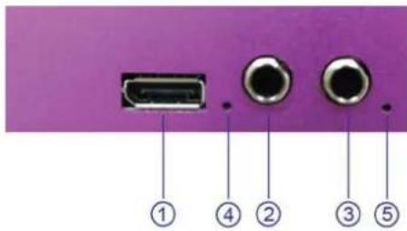
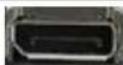
Input Interface
text_image
① ④ ② ③ ⑤Interfaces

DP Input Port Audio Input port
④⑤ Indicator
DP Input
Input the video signal from computer.
Audio Input
Input audio signals from DVD player, set top box, hardware player, etc.

Indicator
When input analog audio signal, LED indicator4, 5 light, when input digital AES/EBU signal, LED indicator4 lights.
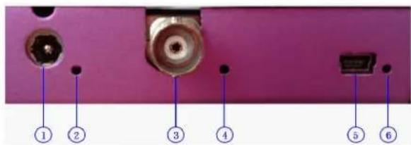
Output and Other Interface
text_image
① ② ③ ④ ⑤ ⑥Interfaces
① Power 2 ③ SDI Output port
○④⑥ Indicator ⑤USB Interface
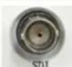
SDI Output
Can connect the next level device with SDI interface.
USB Interface
Used to control the computer.
text_image
ase refer to com. d installer IMPORTANT Refer to www.rgblink.com for the complete user manual and installation instructions before connecting the product to the power source.Indicator
Power indicator 2 lights when device has power supply.
LED indicator 4 lights when output SDI signal. LED indicator 6 lights when connect USB to computer.
Power
Connect one end of the power adapter with the device, the other end into a socket. Plug in, power indicator light means the device works normally. The device uses the standard 12V/3A power supply.
Dial Switch
text_image
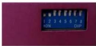
1 2 3 4 5 6 7 8 ION DIPFunctional Description Block Diagram
text_image
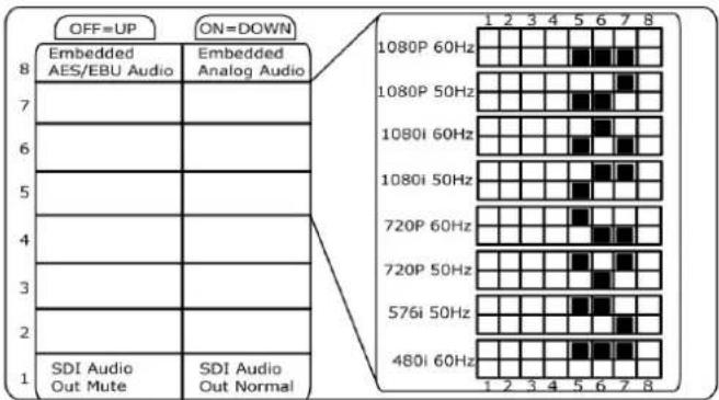
OFF=UP ON=DOWN 8 Embedded AES/EBU Audio Embedded Analog Audio 7 6 5 4 3 2 1 SDI Audio Out Mute SDI Audio Out Normal 1 2 3 4 5 6 7 8 1080P 60Hz 1080P 50Hz 1080i 60Hz 1080i 50Hz 720P 60Hz 720P 50Hz 576i 50Hz 480i 60Hz 1 2 3 4 5 6 7 8Instructions
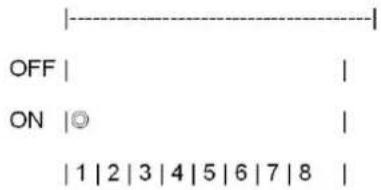
The dial switch upwards is OFF, downwards is ON: 1. Dial switch1 OFF: mute.
text_image
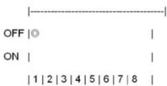
OFF |○ ON | |1|2|3|4|5|6|7|8 |- Dial switch 1 ON: cancel mute.
text_image
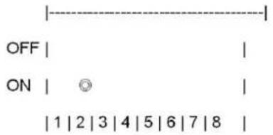
OFF | | ON |◎ | |1|2|3|4|5|6|7|8 |- Dial switch 2 must be set to ON.
text_image
OFF ON 1 | 2 | 3 | 4 | 5 | 6 | 7 | 8- Dial switch 5, 6, 7 ON: SDI output resolution is 1080p 60Hz.
text_image
OFF ON 1 | 2 | 3 | 4 | 5 | 6 | 7 | 8- Dial switch 5, 6 ON, dial switch 7 OFF: SDI output resolution is 1080p 50Hz.
text_image
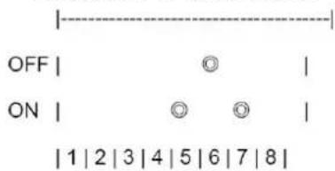
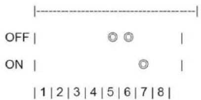
OFF | Ⓞ | ON | Ⓞ Ⓞ | | 1 | 2 | 3 | 4 | 5 | 6 | 7 | 8 |- Dial switch 5, 7 ON, dial switch 6 OFF: SDI output resolution is 1080i 60Hz.
text_image
OFF ON 1 | 2 | 3 | 4 | 5 | 6 | 7 | 8- Dial switch 5 ON, dial switch 6, 7 OFF: SDI output resolution is 1080i 50Hz.
text_image
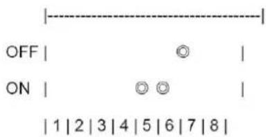
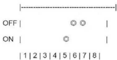
OFF | Ⓞ Ⓞ | ON | Ⓞ | 1 2 3 4 5 6 7 8 |- Dial switch 5 OFF, dial switch 6, 7 ON: SDI output resolution is 720p 60Hz.
text_image
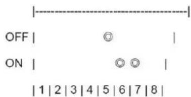
OFF | Ⓞ | ON | Ⓞ Ⓞ | | 1 | 2 | 3 | 4 | 5 | 6 | 7 | 8 |- Dial switch 5, 7 OFF, dial switch 6 ON: SDI output resolution is 720p 50Hz.
text_image
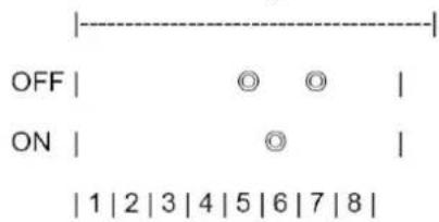
OFF | Ⓞ Ⓞ | ON | Ⓞ | 1 2 3 4 5 6 7 8 |- Dial switch 5, 6 OFF, dial switch 7 ON: SDI output resolution is 576i 50Hz.
text_image
OFF | Ⓞ Ⓞ | | ON | Ⓞ | | | 1 | 2 | 3 | 4 | 5 | 6 | 7 | 8 |- Dial switch 5, 6 7 OFF: SDI output resolution is 480i 60Hz.
text_image
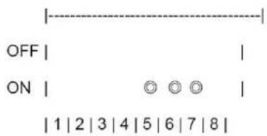
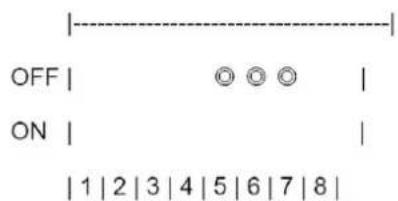
OFF | ○ ○ ○ | ON | | 1 | 2 | 3 | 4 | 5 | 6 | 7 | 8 |- Dial switch 8 OFF: AES/EBU output, no analog audio output.
text_image
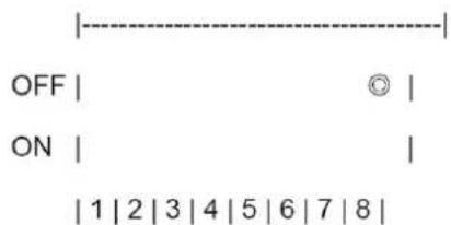
OFF | © | ON | | | 1 | 2 | 3 | 4 | 5 | 6 | 7 | 8 |- Dial switch 8 ON: L-analog and R-analog audio output, no AES/EBU output.
text_image
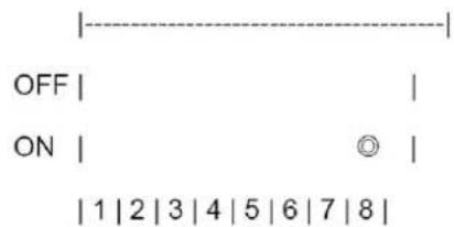
OFF | | ON | Ⓞ | | 1 | 2 | 3 | 4 | 5 | 6 | 7 | 8 |Functional Description
Functional Description
- DP input to SDI output.
- Support input resolution of VESA: 800*600@60Hz, 1024*768@60Hz, 1280*720@60Hz, 1280*768@60Hz, 1280*800@60Hz, 1280*1024@60Hz, 1360*768@60Hz, 1366*768@60Hz, 1440*900@60Hz, 1400*1050@60Hz, 1600*1200@60Hz, 1680*1050@60Hz, 1920*1080@60Hz.
-
Support output resolution of SMPTE: 480i, 576i, 720p@50Hz, 720p@60Hz, 1080i@50Hz, 1080i@60Hz, 1080p@50Hz, 1080p@60Hz.
-
Support SCALE, left and right analog sound channel input, digital AES/EBU input, CVBS embedded audio input and mute function.
-
The LED indicator beside SDI interface lights when output SDI signal.
When input analog audio signal, the LED indicators beside L-ANALOG and R-ANALOG light.
When input digital AES/EBU signal, the LED indicator beside L-ANALOG or AES/EBU lights.
Functional Description Block Diagram
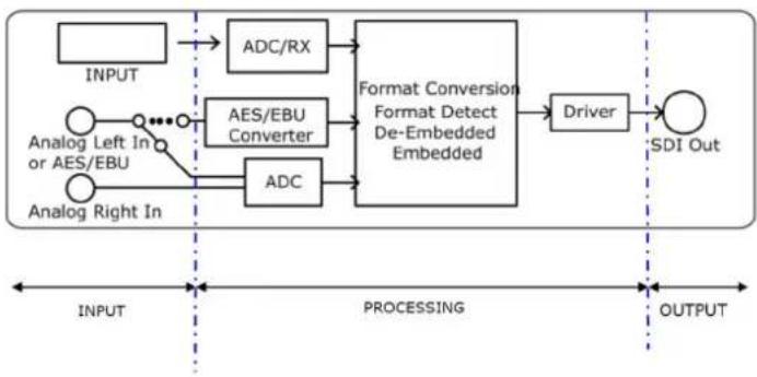
flowchart
graph LR
    A["INPUT"] --> B["ADC/RX"]
    C["Analog Left In or AES/EBU"] --> D["AES/EBU Converter"]
    E["Analog Right In"] --> F["ADC"]
    B --> G["Format Conversion Format Detect De-Embedded Embedded"]
    D --> G
    F --> G
    G --> H["Driver"]
    H --> I["SDI Out"]

    subgraph INPUT
        J["•"]
        K["•"]
        L["•"]
    end

    subgraph Processing
        M["•"]
        N["•"]
        O["•"]
    end

    subgraph OUTPUT
        P["•"]
        Q["•"]
        R["•"]
    end