CMA270W - Tilbehør til projektor Chief - Gratis brugsanvisning og manual
Find enhedens vejledning gratis CMA270W Chief i PDF-format.

Brugerspørgsmål om CMA270W Chief
0 spørgsmål om dette apparat. Besvar dem du kender, eller stil dit eget.
Stil et nyt spørgsmål om dette apparat
Download vejledningen til din Tilbehør til projektor i PDF-format gratis! Find din vejledning CMA270W - Chief og tag din elektroniske enhed tilbage i hånden. På denne side er alle dokumenter nødvendige for brugen af din enhed offentliggjort. CMA270W af mærket Chief.
BRUGSANVISNING CMA270W Chief
INSTALLATION INSTRUCTIONS
natural_image
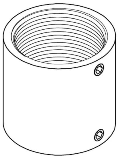
Technical line drawing of a cylindrical mechanical component with concentric grooves and two mounting holes (no text or symbols)Threaded Pipe Coupler
DISCLAIMER
Milestone AV Technologies and its affiliated corporations and subsidiaries (collectively "Milestone"), intend to make this manual accurate and complete. However, Milestone makes no claim that the information contained herein covers all details, conditions or variations, nor does it provide for every possible contingency in connection with the installation or use of this product. The information contained in this document is subject to change without notice or obligation of any kind. Milestone makes no representation of warranty, expressed or implied, regarding the information contained herein. Milestone assumes no responsibility for accuracy, completeness or sufficiency of the information contained in this document.
Chief® is a registered trademark of Milestone AV Technologies. All rights reserved.

IMPORTANT SAFETY INSTRUCTIONS

WARNING: A WARNING alerts you to the possibility of serious injury or death if you do not follow the instructions.

CAUTION: A CAUTION alerts you to the possibility of damage or destruction of equipment if you do not follow the corresponding instructions.

WARNING: Failure to read, thoroughly understand, and follow all instructions can result in serious personal injury, damage to equipment, or voiding of factory warranty! It is the installer's responsibility to make sure all components are properly assembled and installed using the instructions provided.

WARNING: Failure to provide adequate structural strength for this component can result in serious personal injury or damage to equipment! It is the installer's responsibility to make sure the structure to which this component is attached can support five times the combined weight of all equipment. Reinforce the structure as required before installing the component.

WARNING: Exceeding the weight capacity can result in serious personal injury or damage to equipment! It is the installer's responsibility to make sure the combined weight of all components located between the CMA270 up to (and including) the display/projector does not exceed 500 lbs (226.8 kg). The capacity of CMA270 may be limited to the lowest rated capacity of any component located between the CMA270 and the supporting structure!

WARNING: Use this mounting system only for its intended use as described in these instructions. Do not use attachments not recommended by the manufacturer.

WARNING: Never operate this mounting system if it is damaged. Return the mounting system to a service center for examination and repair.

WARNING: Do not use this product outdoors.
--SAVE THESE INSTRUCTIONS--
DIMENSIONS
DIMENSIONS: [MILLIMETERS] INCHES
![[56.134] 2.210 1 1/2" NPT](/content/2026/05/882668/images/609062fcc3bea9b2a6842dadeb185a9827004bea70efb55f4a4d6b64d4a5142c.jpg)
![[52.578] 2.070 2X SET SCREW](/content/2026/05/882668/images/fee0790eb6a7948a0f77c6ef81f54157efaad0dd2125e2215228a97ee741b01f.jpg)
natural_image
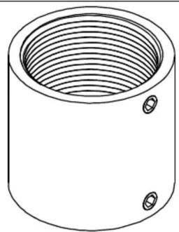
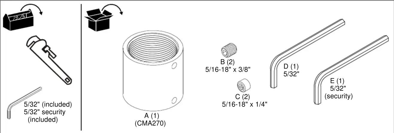
Simple line drawing of a cylindrical mechanical component with concentric grooves and two mounting holes (no text or symbols)TOOLS FOR INSTALLATION / PARTS
INSTALLATION

WARNING: Exceeding the weight capacity can result in serious personal injury or damage to equipment! It is the installer's responsibility to make sure the combined weight of all components attached to the CMA270 does not exceed 500 lbs (227 kg).
- The capacity of CMA270 may be limited to the lowest rated capacity of any component located between the CMA270 and the supporting structure!
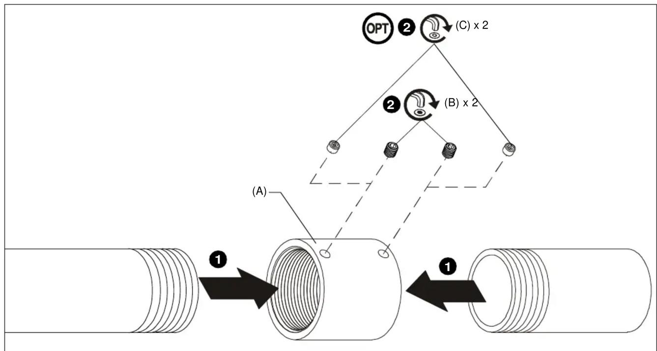
- Install 1-1/2" NPT or NPSM following ANSI/ASME B1.20.1 (Schedule 40, 0.154" minimum thickness aluminum - ASTM B221) threaded extension columns (not included) into CMA270 (A) until tight, with a minimum of four threads engaged. (See Figure 1)
-
Using hex keys (D or E), secure extension columns by one of the following methods (See Figure 1):
-
Install two 5/16-18" x 3/8" set screws (B) into threaded holes, tightening firmly against columns.
- OPTIONAL: Install two 5/16-18" x 1/4" security set screws (C) into threaded holes, tightening firmly against columns.
flowchart
graph TD
    A["Opt"] --> B["(C) x 2"]
    C["(A)"] --> D["(B) x 2"]
    style A fill:#f9f,stroke:#333
    style B fill:#ccf,stroke:#333
    style C fill:#cfc,stroke:#333
    style D fill:#fcc,stroke:#333
Figure 1
Installation Instructions


Mærke : Chief
Model : CMA270W
Kategori : Tilbehør til projektor