SEG-035 - Adgangskontrolsystem Steren - Gratis brugsanvisning og manual
Find enhedens vejledning gratis SEG-035 Steren i PDF-format.

Brugerspørgsmål om SEG-035 Steren
0 spørgsmål om dette apparat. Besvar dem du kender, eller stil dit eget.
Stil et nyt spørgsmål om dette apparat
Download vejledningen til din Adgangskontrolsystem i PDF-format gratis! Find din vejledning SEG-035 - Steren og tag din elektroniske enhed tilbage i hånden. På denne side er alle dokumenter nødvendige for brugen af din enhed offentliggjort. SEG-035 af mærket Steren.
BRUGSANVISNING SEG-035 Steren
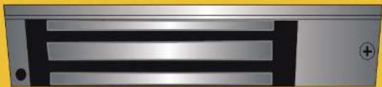
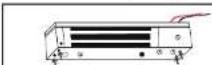
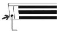
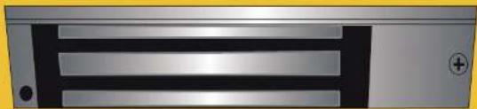
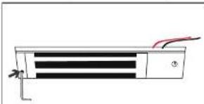
Chapa electromagnética
natural_image
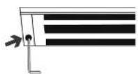
Close-up of a metallic electronic device with three horizontal slots and a plus button (no visible text or symbols)SEG-035
V1.0
Manual de Instrucciones
1018A
Por favor, lee atentamente este instructivo para saber cómo utilizar adecuadamente el producto.
La información que se muestra en este manual sirve únicamente como referencia. Debido a actualiza- ciones pueden existir diferencias. Consulta nuestra página
Precauciones
- Este aparato no se declina para utilizarse por personas (incluyendo niños) cuyas capacidades físicas, sensoriales o mentales sean diferentes o están reducidas, o carezcan de experiencia o conocimiento. - Los niños deben supervisarse para asegurar que no empleen el aparato como jugote.
- Este producto no debe limpiarse con solventes ni líquidos químicos agresivos.
CONTENIDO
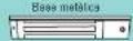

Contrachapa
con piarhla

Ternio
M8×35
1000

Llave Allen da 5 mm

Leave Allen de 3 mm

Tuorca
topo
remate
M8 x 30
mm

Pla 24 para madena (x8)

Rondana de plástica

Rondania de metal

Guia metalica
de 15 mm
(×2)
INSTALACIÓN
Cable para la alimentación
Antes de instalar la chapa, debes disponer de ice cable que la alimentarán.
natural_image
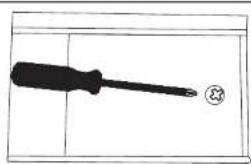
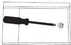
Simple line drawing of a screwdriver with a circular mark on the end (no text or symbols)- Retra el forillo de la cuberta
natural_image
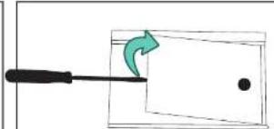
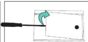
Simple line drawing of a screwdriver inserted into a rectangular block with a green arrow indicating rotation (no text or symbols)- Reira la cubierta. Puedes auxiliante con un desarmador piano y colgada para hacer palanco.
natural_image
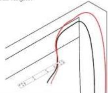
Simple line drawing of an open room with a coiled tube and red heating element (no text or symbols)- Colara un cable de 15 cm en cada uno de los boronas. Trata de que los cables sean de diferente color para identificar la polaridad posteriormente.
natural_image
Simple line drawing of an electrical circuit with wires and components (no text or symbols)- Pasa el cable por el crítico dispuesto a un ocelado del compartimiento.
natural_image
Simple line drawing of a rectangular frame with a hanging hook and a small circular symbol on the right side (no text or labels)- Colaca la cubierta y fijala con el tomile.
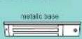
Chapa
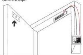
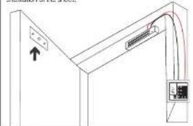
Previamente a esta instalación, el marco de la puerta debe de contar con el cable de alimentación para la chapa (sin que este energizado).
natural_image
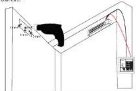
Simple line drawing of a rectangular electronic component with three horizontal bars and a red wire, no text or symbols present.- Usa la lava Alen de 3 mm para retirar el prisionero superior,
-
Introduce la lave en los orificios y allójelos para retrar la base meáica de la chapa.

Cuida la orientación y posición de esta base para colocada de igual manera, poslancamiento. -
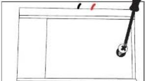
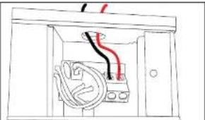
Pasa el table de alimentación de la sistema de apertura por al oficio triangular.
text_image
5.24 3.7 0.8- Fija la base con las 8 pijas de 3/4 en los cechos indicados.
text_image
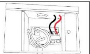
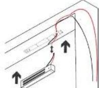
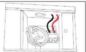
Diagram showing a curved surface with downward arrows and a red curve, possibly indicating a flow or force direction.- Correcta los cables de alimentación de la sistema de apertura con los cables que instalarse anteriormente en la chapa.

text_image
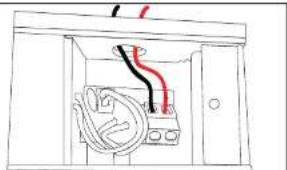
6. Acomode el cable y coloca la chapa en la base. 7. Fija la chapa con la base, apretando los tornillos que achojaca antastadmente.B. Coloca el prisionero nuevamente.
Contrachapa
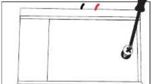
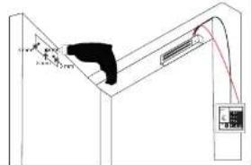
- Pegs la plantilla en la puerta, a la altura y con la orientación que tiene la chapa.
natural_image
Pure technical line drawing of a mechanical assembly with no text or symbols- Realiza la perforación central con una broca de 6 mm de diámetro.
text_image
Technical diagram showing a mechanical or electrical component with labeled parts and connection lines-
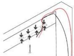
Realiza los criterios laterales con una broca de 5 mm, a una profundidad de 1 cm.
-
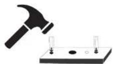
Coloca las guías en los orificios marcados, con el chafán hacia azajo, y auxiliato de un manojo para introduciones.

-
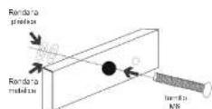
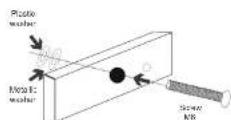
introduce el tómilo en la bonirachapa. En el otro extremo coloce la rendana malática y despues la plástica.
-
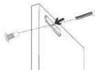
Cooca la contrachapa en la puerta, nasiendo coincidir las guías y el lomillo en sus respectivos ornos.

Asegura la contrachapa con la luorca M8 y aprieta con la lavo Alon de 5 mm.
USO ESPECIFICACIONES
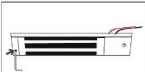
Energiza la chapa con un volaje de 12 V/24 V de corriente directa. Cuando la comorte circula en el circuito, la chapa ganorrata un campo magnético para retener la contrachapa.
Fuerza soportada: 280 kg (600 lbs) Alimentación: 12 V = 500 mA / 24 V = 250 mA
Electromagnetic lock
natural_image
Close-up of a metallic electronic device with three horizontal slots and a plus button (no visible text or symbols)SEG-035
V1.0
Instruction manual
1018A
Please read this instruction carefully to know how to properly use the product.
The information shown in this manual is for reference only. Due to updates there may be differences. Check our page
Cautions
• This device is not intended for use by people (including children), whose physical sensory or mental abilities are different or reduced, or who lack experience or knowledge.
• Children should be supervised to ensure they do not use the device as a toy.
• This product should not be cleaned with solvents or aggressive chemical liquids.
CONTENT

Plywood with template

S010M8×35

Allen
wronch
5 mm

Allen
arench
3 mm

River
Type not
MS x 30
cm

Pipe 5 for wood (x8)

Plastic washer

Metal washer

Metallic guide 15 mm (x2)
INSTALLATION
Cable for feeding
Before installing the sheet, you must have the cables that will feed it.
natural_image
Simple line drawing of a screwdriver with a circular end (no text or symbols)- Remove the screw from the cover
natural_image
Simple line drawing of a tool interacting with a rectangular object, showing a green arrow and dot (no text or symbols)- Remove the cover. You can help with a flat, thin screwdriver to pry.
natural_image
Simple line drawing of an electrical cabinet with cables and a red pipe (no text or symbols)- Place a 15 cm cable in each of the terminals. Try that the wires are of different colors to identify the polarity later.
natural_image
Simple line drawing of an electrical outlet with wires and components (no text or symbols)- Pass the cable through the hole on the side of the compartment
natural_image
Simple line drawing of a rectangular frame with a hanging hook and a small red mark (no text or symbols)- Place the cover and fix it with the screw.
Sheet
Prior to this installation, the door frame must have the power cable for the sheet (without being energized).
natural_image
Pure electrical circuit lines without any symbols- Use the 3mm Allen wrench to remove the upper stud.
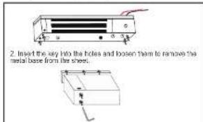
text_image
2. Insert the key into the holes and loosen them to remove the metal base from the sheet.Take care of the orientation and position of this base to place it in the same way, later.
text_image
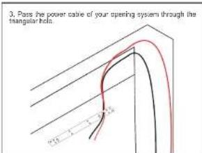
3. Pass the power cable of your opening system through the triangular hold. 12 2 3
text_image
2.10 3.50 4.50- Fix the base with the B screws of 5% in the indicated holes.

text_image
Diagram showing force vectors on a curved surface with arrows indicating direction and label 'G'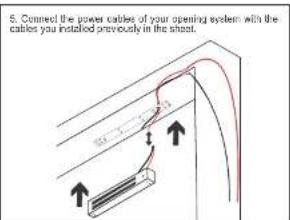
text_image
5. Connect the power cables of your opening system with the cables you installed previously in the sheet.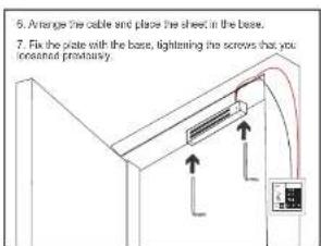
text_image
6. Arrange the cable and plate the sheet in the base. 7. Fix the plate with the base, tightening the screws that you conserved prestancy.- Place the prisoner again.
Plywood
- Stick the template on the door, at the height and with the orientation of the sheet.
natural_image
Pure technical line drawing of a mechanical assembly with no text or symbols- Perform the central drilling with an 8 mm diameter drill bit.
text_image
Technical diagram showing a mechanical or electrical component with labeled parts and connection lines-
Make the side notes with a 5 mm crill, to a depth of 1 cm.
-
Place the guides in the marked holes, with the chamber down, and axelidiate a hammer to introduce them.
-
Insert the screw into the backing. At the other end, place the metal washer and then the plastic one.
-
Place the counter plate on the door, making the guides and the screw coincide in their respective holes.
Secure the backing with the M8 nut and tighten with the 5 mm Allen key.
USE SPECIFICATIONS
Energizes the sheet with a voltage of 12 V / 24 V direct current. When the current circulates in the circuit, the sheet will generate a magnetic field to retain the counter place.
Supported force: 280 kg (600 lbs) Input: 12 V = 500 mA / 24 V = 260 mA