KJ-6000 - Karaoke Vocopro - Gratis brugsanvisning og manual
Find enhedens vejledning gratis KJ-6000 Vocopro i PDF-format.

Brugerspørgsmål om KJ-6000 Vocopro
0 spørgsmål om dette apparat. Besvar dem du kender, eller stil dit eget.
Stil et nyt spørgsmål om dette apparat
Download vejledningen til din Karaoke i PDF-format gratis! Find din vejledning KJ-6000 - Vocopro og tag din elektroniske enhed tilbage i hånden. På denne side er alle dokumenter nødvendige for brugen af din enhed offentliggjort. KJ-6000 af mærket Vocopro.
BRUGSANVISNING KJ-6000 Vocopro
VocoPro
ULTIMATE CHOICE OF KARAOKE ENTERTAINMENT
Features:
● New Space Saving Rack Design, Just 4 spaces!
● 2 Source Channels (CD/AV/PHONO Selectable) and 4 Mic Channels (1 (XLR), 3 (1/4")
● 2 Video Inputs and 2 Video Outputs for Multi-screen Video Options
● Convenient On-board Video Switching making video syncing a snap!
- Assignable 24-step Digital Key Controller for Both Stereo and Mic Channels (1/2-Step) with Jog Dial
● Digital Echo with Repeat and Delay Controls for Vocal Enhancement
● DSP Effects: Pseudo-Stereo, Live, Movie & Karaoke for Music Enhancement
● Vocal Cancel and Partner Modes for Multiplex Media Vocal Cancellation, and Vocal Elimination for Standard CD Vocal Cancellation
● 3-Band Graphic Equalizer for Precise Room Tuning
● 2 Master Outputs (RCA), 1 Record Output (RCA)
- Replaceable Assignable Crossfader
● 110V-230V Compatible
natural_image
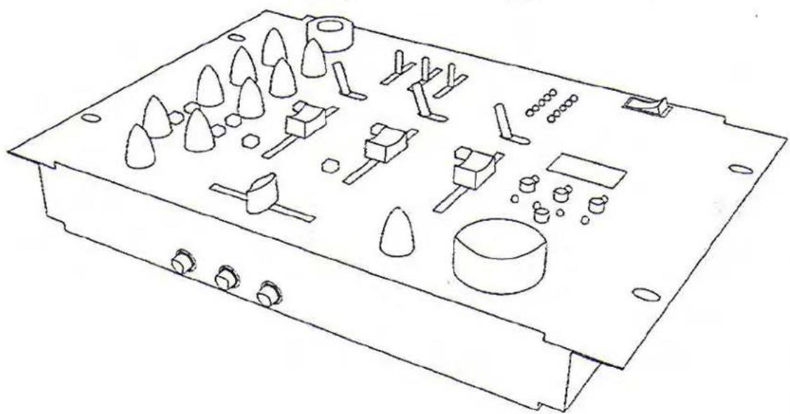
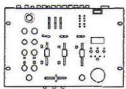
Line drawing of an electronic device casing with various components and mounting holes (no text or symbols)KJ-6000
Digital Kareoke Mixer With Digital Key Control
Safety Instructions
CAUTION
RISK OF SHOCK
CAUTION: To reduce the risk of electric shock, do not remove cover (or back). No user-serviceable parts inside. Only refer servicing to qualified service personnel.
Explanation of Graphical Symbols
The lightning flash & arrowhead symbol, within an equilateral triangle, is intended to alert you to the presence of danger.
The exclamation point within an equilateral triangle is intended to alert you to the presence of important operating and servicing instructions.
WARNING
To reduce the risk of fire or electric shock, do not expose this unit to rain or moisture.
- Read Instructions - All the safety and operating instructions should be read before the appliance is operated.
- Retain Instructions - The safety and operating instructions should be retained for future reference.
- Heed Warnings - All warnings on the appliance and in the operating instructions should be adhered to.
- Follow Instructions - All operating and use instructions should be followed.
- Attachments - Do not use attachments not recommended by the product manufacturer as they may cause hazards.
- Water and Moisture - Do not use this unit near water. For example, near a bathtub or in a wet basement and the like.
- Carts and Stands - The appliance should be used only with a cart or stand that is recommended by the manufacturer.
7 A. An appliance and cart combination should be moved with care. Quick stops, excessive force, and uneven surfaces may cause an overturn.

- Ventilation - The appliance should be situated so its location does not interfere with its proper ventilation. For example, the appliance should not be situated on a bed, sofa, rug, or similar surface that may block the ventilation slots.
-
Heat - The appliance should be situated away from heat sources such as radiators, heat registers, stoves, or other appliances (including amplifiers) that produce heat.
-
Power Sources - The appliance should be connected to a power supply only of the type described in the operating instructions or as marked on the appliance.
-
Grounding or Polarization - Precautions should be taken so that the grounding or polarization means of an appliance is not defeated.
-
Power-Cord Protection - Power-supply cords should be routed so that they are not likely to be walked on or pinched by items placed upon or against them, paying particular attention to cords at plugs, convenience receptacles, and the point where they exit from the appliance.
-
Cleaning - Unplug this unit from the wall outlet before cleaning. Do not use liquid cleaners or aerosol cleaners. Use a damp cloth for cleaning.
-
Power lines - An outdoor antenna should be located away from power lines.
-
Nonuse Periods - The power cord of the appliance should be unplugged from the outlet when left unused for a long period of time.
-
Object and Liquid Entry - Care should be taken so that objects do not fall and liquids are not spilled into the enclosure through openings.
-
Damage Requiring Service - The appliance should be serviced by qualified service personnel when:
A. The power supply cord or plug has been damaged; or
B. Objects have fallen into the appliance; or
C. The appliance has been exposed to rain; or
D. The appliance does not appear to operate normally or exhibits a marked change in performance; or
E. The appliance has been dropped, or the enclosure damaged.
- Servicing - The user should not attempt to service the appliance beyond that described in the operating instructions. All other servicing should be referred to qualified service personnel.
Note:
To CATV system installer's (U.S.A.): This reminder is provided to call the CATV system installer's attention to Article 820-40 of the NEC that provides guidelines for proper grounding and, in particular, specifies that the cable ground shall be connected as close to the point of cable entry as practical.
FCC INFORMATION (U.S.A.)
1. IMPORTANT NOTICE: DO NOT MODIFY THIS
UNIT!: This product, when installed as indicated in the instructions contained in this manual, meets FCC requirements. Modifications not expressly approved by Vocopro may void your authority, granted by the FCC, to use this product.
-
IMPORTANT: When connecting this product to accessories and/or another product use only high quality shielded cables. Cable(s) supplied with this product MUST be used. Follow all installation instructions. Failure to follow instructions could void your FCC authorization to use this product in the U.S.A.
-
NOTE: This product has been tested and found to comply with the requirements listed in FCC Regulations, Part 15 for Class "B" digital devices. Compliance with these requirements provides a reasonable level of assurances that your use of this product in a residential environment will not result in harmful interference with other electronic devices. This equipment generates/uses radio frequencies and, if not installed and used according to the instructions found in the owner's manual, may cause interference harmful to the operation of other electronic devices. Compliance with FCC regulations does not guarantee that interference will not occur in all installations. If this product is found to be the source of interference, which can be determined by turning the unit "Off" and "On", please try to eliminate the problem by using one of the following measures:
Relocate either this product or the device that is being affected by the interference.
Use power outlets that are on different branch (circuit breaker or fuse) circuits or install AC line filter(s).
In the case of radio or TV interference, relocate/reorient the antenna. If the antenna lead-in is 300-ohm ribbon lead, change the lead-in to coaxial type cable.
If these corrective measures do not produce satisfactory results, please contact your local retailer authorized to distribute Vocopro products. If you can not locate the appropriate retailer, please contact Vocopro, 1728 Curtiss Court, La Verne, CA 91750.
CAUTION:
READ THIS BEFORE OPERATING YOUR UNIT
-
To ensure the finest performance, please read this manual carefully. Keep it in a safe place for future reference.
-
Install your unit in a cool, dry, clean place - away from windows, heat sources, and too much vibration, dust, moisture or cold. Avoid sources of hum (transformers, v motors). To prevent fire or electrical shock, do not expose to rain and water.
-
Do not operate the unit upside-down.
-
Never open the cabinet. If a foreign object drops into the set, contact your dealer.
-
Place the unit in a location with adequate air circulation. Do not interfere with its proper ventilation; this will cause the internal temperature to rise and may result in a failure.
-
Do not use force on switches, knobs or cords. When moving the unit, first turn the unit off. Then gently disconnect the power plug and the cords connecting to other equipment. Never pull the cord itself.
-
Do not attempt to clean the unit with chemical solvents: this might damage the finish. Use a clean, dry cloth.
-
Be sure to read the "Troubleshooting" section on common operating errors before concluding that your unit is faulty.
-
This unit consumes a fair amount of power even when the power switch is turned off. We recommend that you unplug the power cord from the wall outlet if the unit is not going to be used for a long time. This will save electricity and help prevent fire hazards. To disconnect the cord, pull it out by grasping the plug. Never pull the cord itself.
-
To prevent lightning damage, pull out the power cord and remove the antenna cable during an electrical storm.
-
The general digital signals may interfere with other equipment such as tuners or receivers. Move the system farther away from such equipment if interference is observed.
CAUTION
The apparatus is not disconnected from the AC power source so long as it is connected to the wall outlet, even if the apparatus itself is turned off. To fully insure that the apparatus is indeed fully void if residual power, leave unit disconnected from the AC outlet for at least fifteen seconds.
NOTE:
Please check the copyright laws in your country before recording from records, compact discs, radio, etc. Recording of copyrighted material may infringe copyright laws.
And Thank you for purchasing the KJ-6000 from VocoPro, your ultimate choice in Karaoke entertainment! With years of experience in the music entertainment business, VocoPro is a leading manufacturer of Karaoke equipment, and has been providing patrons of bars, churches, schools, clubs and individual consumers the opportunity to sound like a star with full-scale club models, in-home systems and mobile units. All our products offer solid performance and sound reliability, and to further strengthen our commitment to customer satisfaction, we have customer service and technical support professionals ready to assist you with your needs. We have provided some contact information for you below.
VocoPro
1728 Curtiss Court
La Verne, CA 91750
Toll Free: 800-678-5348
TEL: 909-593-8893
FAX: 909-593-8890
VocoPro Company Email Directory
Customer Service & General Information
info@vocopra.com
Tech Support
techsupport@vocopro.com
Remember Our Website
Be sure to visit the VocoPro website www.vocopro.com for the latest information on new products, packages and promos. And while you're there don't forget to check out our Club VocoPro for Karaoke news and events, chat rooms, club directories and even a KJ Service directory!
We look forward to hearing you sound like a PRO, with VocoPro, your ultimate choice in Karaoke entertainment.
FOR YOUR RECORDS
Please record the model number and serial number below, for easy reference, in case of loss or theft. These numbers are located on the rear panel of the unit. Space is also provided for other relevant information
Model Number ____ ____ ____ ____
Serial Number ____ ____ ____
Date of Purchase
Place of Purchase ____ ____ ____ ____
KJ-6000
Digital Karaoke Mixer with Digital Key Control
Contents
Introduction
Safety Instructions.... 1-2
Welcome.... 3
Specifications.... 4
Hearing For a Lifetime.... 5
Before Getting Started
Unpacking.... 6
Mounting....6
Getting Connected
Phone Sources....7
Line Level Sources....7
A/V Sources 8
Video....8
Output....9
Microphones....9
Controls and Functions
Microphone Channel 10
Stereo Panel 11
Master Panel 12-13
Front Panel.... 14
Rear Panel 14
Operations
Operations.... 16

natural_image
Cartoon illustration of a lion wearing a crown and holding an object (no text or symbols)
ULTIMATE CHOICE OF KARAOKE ENTERTAINMENT
Specifications
INPUTS:
MICRO 1\~4: 1.5mV/1K ohms (Balanced XLR Jack)
PHONO: 3mV/47K ohms (RCA Jack)
AV 1,2/CD: 150mV/10K ohms (RCA Jack)
OUTPUTS:
MASTER 1, 2: 1.0V/600 ohms (RCA / Unbalanced)
RECORD OUT: 1.0V/600 ohms (RCA / Unbalanced)
HEADPHONES: 500mV/320
MICROPHONE TONE CONTROL:
TREBLE: +/-15dB
BASS: +/-15dB
MASTER EQUALIZER:
TREBLE: +/-12dB
MID: +/-12dB
BASS: +/-12dB
NOISE RATIO:
MICRO: >80dB
CD/LINE: >92dB
T.H.D: <0.05%
FREQUENCY RESPONSE:
20Hz\~20KHz+/-0.5dB
ECHO DELAY TIME:
Max. 300 mS
DIGITAL STEREO KEY:
12 steps up & down 1 octave
DIMENSIONS:
322 (W) × 191 (D) × 43 (H) (mm)
WEIGHT:
1.5Kgs
Listening For A Lifetime
Selecting fine audio equipment such as the unit you've just purchased is only the start of your musical enjoyment. Now it's time to consider how you can maximize the fun and excitement your equipment offers. VocoPro and the Electronic Industries Association's Consumer Electronics Group want you to get the most out of your equipment by playing it at a safe level. One that lets the sound come through loud and clear without annoying blaring or distortion and, most importantly, without affecting your sensitive hearing.
Sound can be deceiving. Over time your hearing 'comfort level' adapts to a higher volume of sound. So what sounds 'normal' can actually be loud and harmful to your hearing. Guard against this by setting your equipment at a safe level BEFORE your hearing adapts.
To establish a safe level:
- Start your volume control at a low setting
- Slowly increase the sound until you can hear it comfortably and clearly, and without distortion.
Once you have established a comfortable sound level:
- Set the dial and leave it there.
- Pay attention to the different levels in various recordings.
Taking a minute to do this now will help to prevent hearing damage or loss in the future. After all, we want you listening for a lifetime.
Used wisely, your new sound equipment will provide a lifetime of fun and enjoyment. Since hearing damage from loud noise is often undetectable until it is too late, this manufacturer and the Electronic Industries Association's Consumer Electronics Group recommend you avoid prolonged exposure to excessive noise. This list of sound levels is included for your protection.
Some common decibel ranges:
| Level | Example |
| 30 | Quiet library, Soft whispers |
| 40 | Living room, Refrigerator, Bedroom away from traffic |
| 50 | Light traffic, Normal Conversation |
| 60 | Air Conditioner at 20 ft., Sewing machine |
| 70 | Vacuum cleaner, Hair dryer, Noisy Restaurant |
| 80 | Average city traffic, Garbage disposals, Alarm clock at 2 ft. |
The following noises can be dangerous under constant exposure:
| Level | Example |
| 90 | Subway, Motorcycle, Truck traffic, Lawn Mower |
| 100 | Garbage truck, Chainsaw, Pneumatics drill |
| 120 | Rock band concert in front of speakers |
| 140 | Gunshot blast, Jet plane |
| 180 | Rocket launching pad |
-Information courtesy of the Deafness Research Foundation
Before Getting Started
Thank you for purchasing the KJ-6000 Digital KJ/DJ Mixer. At VocoPro we care about product quality and customer satisfaction. We know the KJ-6000 will provide years of high-quality enjoyment and reliable music entertainment for you when used properly.
Unpacking the KJ-6000
Carefully remove the KJ-6000 from its carton. It is recommended that the original packaging materials be retained, should it become necessary to return the product for any reason.
Be Sure You Have the Parts and Components Included with the KJ-6000:
Parts
1-KJ-6000
natural_image
Pure electrical circuit lines without any symbols1- RCA Patch Cable
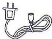
AC Power Cable
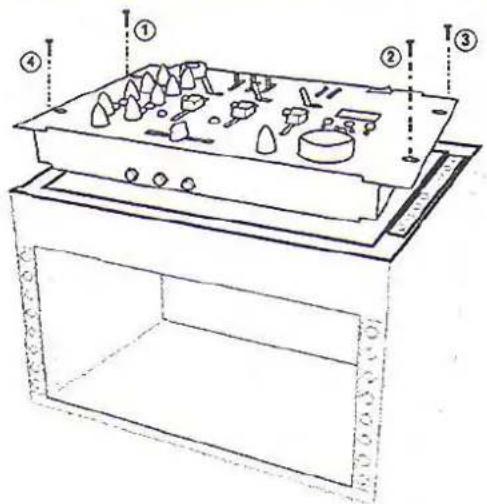
Mounting the KJ-6000
To mount, carefully place the KJ-6000 Pro in the 4 rack-space area of your case. The KJ-6000 Pro takes 4 screws to mount. Make sure holes are aligned evenly. Use an alternating "X" rotation when screwing to ensure even tension and alignment.
Top Mounting
Note:
When top mounting, make sure you have at least 2 rack-spaces of depth available.
Getting Connected
Installation
After you have completed mounting your KJ-6000, it is time to make all the necessary connections to your pre-existing devices to create a complete system. To get connected, follow the easy connection instructions below:
Connecting Phono Sources
(a) Connect the AUDIO OUTPUT jacks of the PHONO player (red and white RCA) to either of the CD1/PH1 or CD2/PH2 AUDIO INPUT jacks (also red and white RCA) on the KJ-6000. NOTE: Ensure that the CD/PH TOGGLE button is set to PH and not CD on the connected channel.
Phono Sources
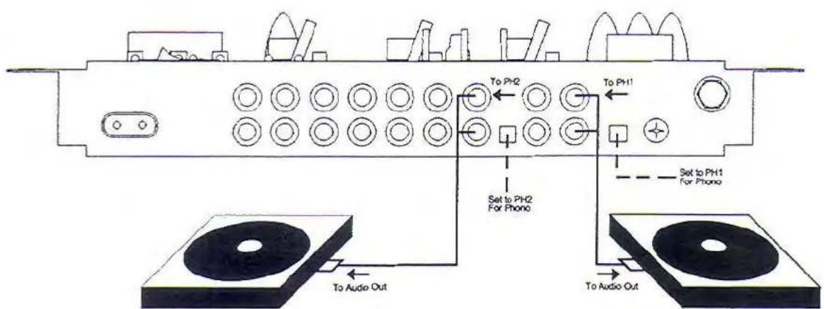
PHONO 2
PHONO 1
Connecting Line-level Audio Sources (CD Player, MP3 Players, etc.)
(b) To make an analog connection, connect the left and right AUDIO OUTPUT jacks of the external device, such as a CD player, to the left and right AUDIO INPUT jacks of the receiving channel on the KJ-6000.
Line-Level Audio
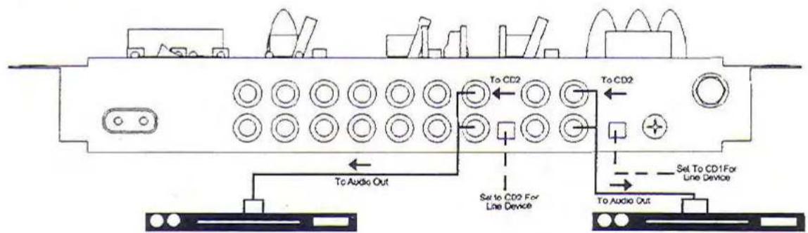
CD PLAYER 2
CD PLAYER 1
Getting Connected cont...
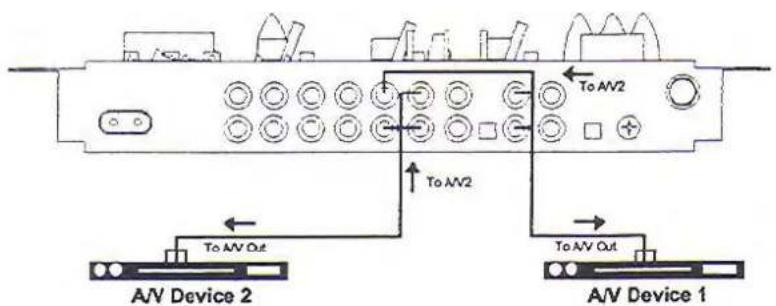
Connecting A/V Sources (CDG, DVD, VCD Players, etc.)
(c) Connect the AUDIO OUTPUT jacks of the AV source player (red and white RCA) to either of the AV1/AV2 AUDIO INPUT jacks (also red and white RCA) on the KJ-6000.
(d) Connect the VIDEO OUTPUT jack of the A/V source player (yellow RCA) to the corresponding VIDEO INPUT jack on KJ-6000.
A/V Sources
NOTE: The AV1 jacks are designated within a GRAY colored panel section, while the AV2 jacks are designated within a solid WHITE colored panel section.
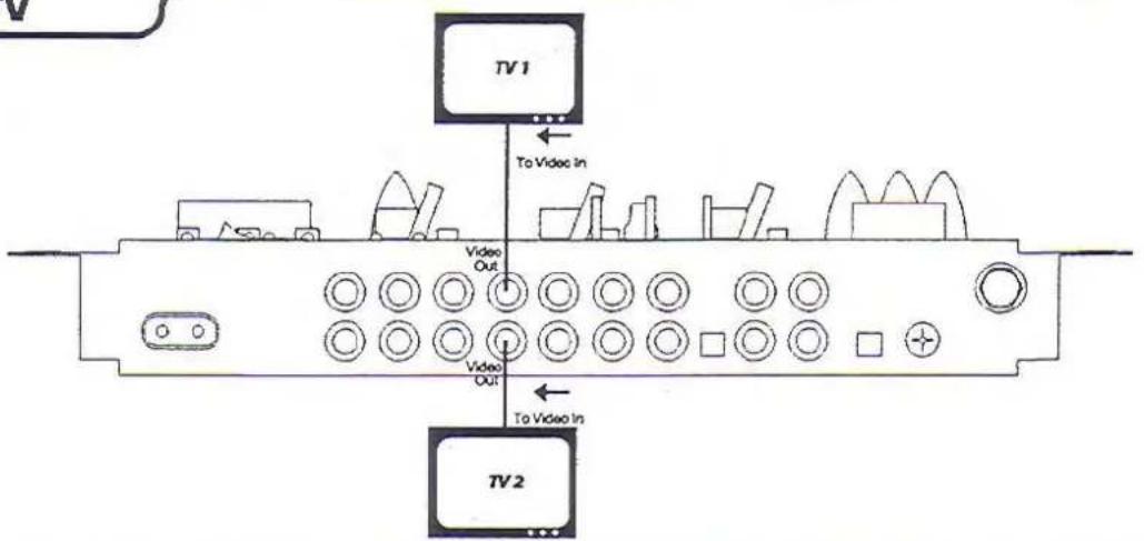
Connecting Video Output to a TV
The KJ-6000 has two VIDEO OUTPUT jacks, both of which output the active video source. Up to two TV's can be connected.
(e) Connect an RCA video cable from the desired VIDEO OUTPUT jack on the KJ-6000 to the VIDEO INPUT jack on the TV. Some TV's will require that you manually switch the TV to the VIDEO INPUT mode. Other TV's will automatically switch to the video mode when they detect a video signal at the Video input jack. On most TV's the jack is labeled AUX or VIDEO.
Video to TV
Getting Connected cont...
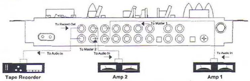
Connecting Output to an External Sound System, Mixer or Recording Device
The KJ-6000 has three pairs of AUDIO OUTPUTS:
MASTER OUT 1: This OUTPUT is for connecting the KJ-6000 directly to the INPUT of a power amplifier, receiver, pre-amp or mixer. Using an RCA cable (or other cable depending on your pre-existing equipment), make connections from the MASTER OUT 1 to the AUDIO INPUTS of your external device.
MASTER OUT 2: This OUTPUT is a secondary MASTER OUT to MASTER OUT 1. Connect it in the same fashion as described above, but to an additional external device.
RECORD OUT 1: This OUTPUT is for connecting directly to a recording device. Using an RCA cable (or other cable depending on your recording device), make connections from the RECORD OUT 1 to the AUDIO INPUTS of your recording device.
External System
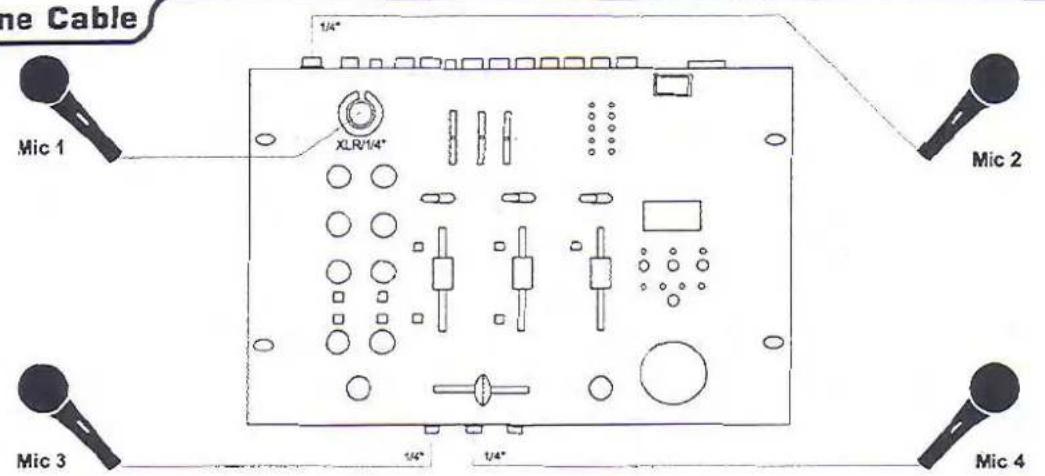
Connecting Microphones to the KJ-6000
The KJ-6000's microphone jacks are located on the TOP (MIC 1), REAR (MIC 2) and FRONT (MIC 3,4) PANELS. The MIC 1 jack will accommodate both an XLR and 14 " style microphone plug. MIC 2, 3 and 4 accommodate 14 " style microphone plugs.
(h) Connect a microphone to any of the desired microphone jacks, ensuring that both ends are firmly and correctly connected.
Microphone Cable
Microphone Channel Controls and Functions
Microphone Channel
flowchart
graph TD
    A["1"] --> B["2"]
    A --> C["3"]
    A --> D["4"]
    A --> E["5"]
    A --> F["6"]
    B --> G[" "]
    C --> H[" "]
    D --> I[" "]
    E --> J[" "]
    F --> K[" "]
    G --> L[" "]
    H --> M[" "]
    I --> N[" "]
    J --> O[" "]
    K --> P[" "]
    L --> Q["7"]
    M --> R["9"]
    N --> S["8"]
-
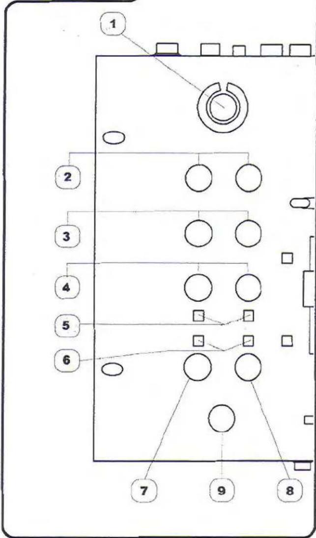
XLR/1/4" MIC 1 jack - This combo jack located on the TOP PANEL can be used to connect either an (XLR) or (12 " MICROPHONE. The 3 / 4 INPUT jack is located in the middle of the jack housing. The XLR INPUT jack is located within the outer perimeter of the jack housing.
-
LEVEL controls - These controls adjust the INPUT LEVELS from connected MICROPHONES. To increase turn clockwise and to decrease turn counter-clockwise. NOTE: The LEVEL control on the left channel strip adjusts LEVELS for MICROPHONE channels 1 and 3, while the LEVEL control on the right channel strip adjusts LEVELS for MICROPHONE channels 2 and 4.
-
TREBLE control - These controls adjust the level of HIGH-FREQUENCY allowed to the MICROPHONE CHANNELS. To increase turn clockwise and to decrease turn counter-clockwise. NOTE: The TREBLE control on the left channel strip adjusts TREBLE for MICROPHONE channels 1 and 3, while the TREBLE control on the right channel strip adjusts TREBLE for MICROPHONE channels 2 and 4.
-
BASS control - These controls adjust the level of LOW-FREQUENCY allowed to the MICROPHONE CHANNELS. To increase turn clockwise and to decrease turn counter-clockwise. NOTE: The BASS control on the left channel strip adjusts BASS for MICROPHONE channels 1 and 3, while the BASS control on the right channel strip adjusts BASS for MICROPHONE channels 2 and 4.
-
ECHO button - These buttons ENABLE/DISABLE the digital ECHO effect applied to the corresponding MICROPHONE channels. When these buttons are DEPRESSED to their outer positions, the ECHO effect is disabled to corresponding MIC CHANNELS. When these buttons are PRESSED to their inner positions, the ECHO effect is enabled to corresponding MIC CHANNELS. NOTE: The ECHO button on the left channel strip applies to MICROPHONE channels 1 and 3, while the ECHO button on the right channel strip applies to MICROPHONE channels 2 and 4.
-
KEY button - These buttons assign DIGITAL KEY CONTROL to the corresponding MICROPHONE CHANNELS. When these buttons are DEPRESSED to their outer positions, DIGITAL KEY CONTROL is disabled to corresponding MIC CHANNELS. When these buttons are PRESSED to their inner positions, DIGITAL KEY CONTROL is enabled to corresponding MIC CHANNELS. NOTE: The KEY button on the left channel strip applies to MICROPHONE channels 1 and 3, while the KEY button on the right channel strip applies to MICROPHONE channels 2 and 4.
-
REPEAT control - This control serves as a master-level REPEAT control for all MICROPHONE channels. As more REPEAT is applied, more echo intervals will be heard prior to fade-out and vice-versa for less REPEAT. To increase turn clockwise and to decrease turn counter-clockwise.
-
DELAY control - This control serves as a master-level DELAY control for all MICROPHONE channels. As more DELAY is applied, more time exists between each echo interval and vice-versa for less DELAY. To increase turn clockwise and to decrease turn counter-clockwise.
-
ECHO control - This control serves as a master-level ECHO control for all MICROPHONE channels. To increase turn clockwise and to decrease turn counter-clockwise
Stereo Panel Controls and Functions
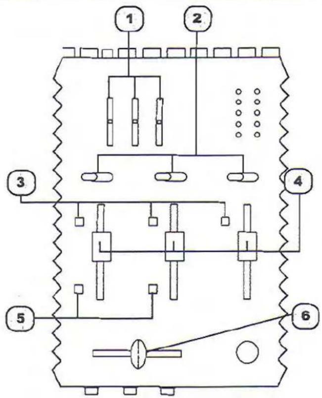
- 3-BAND GRAPHIC EQ - This GRAPHIC EQ provides for precise room tuning by allowing users to adjust specific frequencies either higher or lower in the AUDIO OUTPUT signal. Adjust these LOW, MID and HIGH controls to provide the sound quality that you prefer.
- SOURCE toggle - These switches will toggle between any connected sources that are available for selection. For example, if you have a CDG player connected to the AV1 channel, a standard CD player connected to the CD1/PH1 channel and a turntable connected to the CD2/PH2 channel, you would use these toggles to select the active devices on CHANNEL A and B. The left SOURCE TOGGLE applies to CHANNEL A and the right SOURCE TOGGLE applies to CHANNEL B.
- CUE button - When activated this monitors the input signal from the mix board to the headphones. Press CUE to hear that channel through the headphones.
- CHANNEL fader - These FADERS raise and lower the VOLUME of the channel as it is moved UP and DOWN. These are MASTER level VOLUME controls for the INPUT CHANNELS A and B.
- KEY button - This button assigns DIGITAL KEY CONTROL to the channel. When this button is depressed DIGITAL KEY CONTROL is not assigned to that channel. When this button is pressed in, DIGITAL KEY CONTROL will be applied to that channel.
- CROSSFADER - The CROSSFADER allows the user to fade the music from active INPUT SOURCES connected to CHANNELS A & B. The CROSSFADER allows for DJ-style mixing and fade-in and fade-outs of source audio. NOTE: The CROSSFADER will only fade from the two sources that are assigned active by each of the CHANNEL A & B's SOURCE TOGGLES.
Stereo Panel
Master Panel Controls and Functions
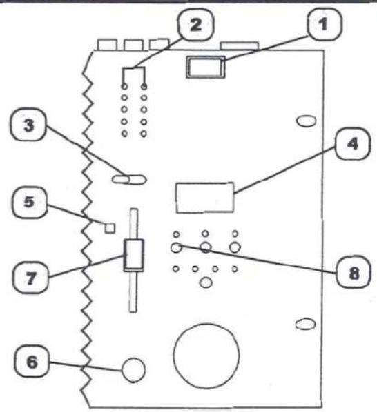
- POWER switch - This button turns the KJ-6000 ON/OFF.
- MASTER OUTPUT LED meters - These LED meters display a graphical indication of MASTER OUTPUT LEVELS. The row of LED's on the left apply to LEFT CHANNEL, while the LED's on the RIGHT apply to the RIGHT CHANNEL. NOTE: When the red LED's begin to illuminate, that is an indication that the OUTPUT levels are too high, clipping and possibly posing damage to system speakers.
- VIDEO SELECTOR toggle - This toggle switch selects the VIDEO CHANNEL that is deemed active and displayed on connected TVs, monitors or LCD screens. To select, set the VIDEO SELECT toggle to the AV channel (1 or 2) where your active AV device is connected.
- DIGITAL KEY CONTROL LED display - This LED display indicates the CURRENT SETTING of the DIGITAL KEY CONTROLLER. Steps DOWN are indicated by the '-' symbol preceding a NUMBER that indicates the number of steps taken. Steps UP are indicated by a NUMBER only, indicating the number of steps taken.
- MASTER 2/CUE button - This button toggles OUTPUT between the MASTER 2 OUTPUT jacks and CUE output (HEADPHONES). When set to CUE, only those channels with the CUE button activated will be audible in the HEADPHONES. When set to MASTER 2, the MASTER 2 OUTPUTS are active and can feed an additional amplifier, mixer or other audio device. NOTE: The MASTER 2/CUE volume levels are controlled with the MASTER 2/CUE level control.
- MASTER 2/CUE OUTPUT control - This control adjusts the OUTPUT VOLUME level of either the MASTER 2 or CUE (HEADPHONES) channel depending on which one the MASTER 2/CUE button is set to. To increase turn clockwise and to decrease turn counter-clockwise.
- MASTER OUTPUT fader - This FADER adjusts the MASTER OUTPUT level being fed to the device connected to the MASTER 1 OUT jacks. To increase level slide FADER up and to decrease level slide FADER down.
- VOCAL PARTNER button - This button enables the CANCELLATION of GUIDE VOCALS on MULTIPLEXED karaoke media when a performer SINGS into an active MICROPHONE. When the performer STOPS SINGING, the GUIDE VOCALS are automatically REINTRODUCED to the mix. Press once to enable (indicated by it's LED illumination), and press again to disable. NOTE: This control only works on MULTIPLEXED formatted karaoke media.
Master Panel
Master Panel Controls and Functions cont...
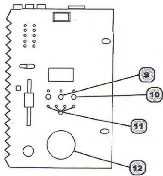
- VOICE ELIMINATOR button - This button enables the CANCELLATION of LEAD VOCALS on STANDARD CD's. Press once to enable (indicated by it's LED illumination), and press again to disable. NOTE: This feature performs differently with each disc due to the different recording methods used today. Some discs may have all the lead vocals removed, while others may leave 25-50% of the vocals still present.
- MULTIPLEX button - This button enables the CANCELLATION of GUIDE VOCALS on MULTIPLEXED karaoke media. Press once to enable (indicated by it's LED illumination), and press again to disable. NOTE: This control only works on MULTIPLEXED formatted karaoke media.
- EFFECTS button - This buttons enables DSP music enhancement to be applied to all SOURCE AUDIO. There are four DSP pre-sets:
Pseudo-stereo - This setting will take a MONO signal and recreate it to the inactive channel for a "stereo effect". It is called pseudo-stereo because the left and right channels are the same audio signal. To enable this mode, press the EFFECT button ONCE (indicated by its LED illumination).
Live - This setting provides a live ambient feeling to the music, recreating the naturally reverberating sound found at a live show. To enable this mode, press the EFFECT button TWICE (indicated by it's LED illumination).
Movie - This setting enhances the overall clarity of the audio signal and smoothes any large differences in dynamic amplitude. To enable this mode, press the EFFECT button THREE times (indicated by it's LED illumination).
Karaoke - This setting provides a natural sounding sonic enhancement to the audio signal, improving the overall sound and lending a slight boost to the original signal. To enable this mode, press the EFFECT button FOUR times (indicated by it's LED illumination).
To cancel any of the DSP EFFECT modes, press the EFFECT button till no YELLOW LED's are illuminated.
12. DIGITAL KEY CONTROLLER jog dial - This JOG DIAL allows you to modify the original key of assigned audio signals without changing their tempo. The DIGITAL KEY CONTROLLER can step UP and DOWN 12-steps, making for a 24-step range total.. To step DOWN, turn the JOG DIAL counter-clockwise and to step UP, turn the JOG DIAL clockwise. To revert back to the ORIGINAL key press the JOG DIAL in till it clicks. NOTE: Digital Key Control changes are only audible to the channels where the KEY button is activated.
Master Panel
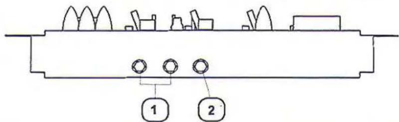
Front Panel Description and Functions
-
¼" MIC 3, 4 jacks - Those ¼" jacks are used to connect MICROPHONES with a ¼" style plug.
-
HEADPHONES OUTPUT jack - This 1/4" jack is for connecting HEADPHONES equipped with a 1/4" plug. Only when the MASTER2/CUE button is set to CUE and one or more MIC/SOURCE channels have the CUE button activated will audio be heard through connected HEADPHONES.
Front Panel
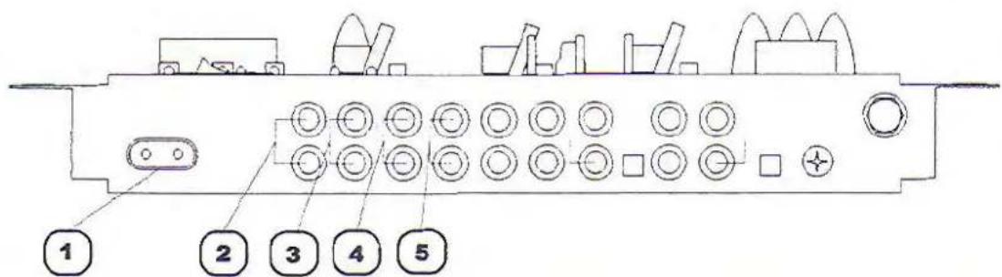
Rear Panel Description and Functions
- AC INPUT - This is the terminal for the AC power cable. Carefully insert the AC power cable here. The AC power cable should fit plush and firm into housing.
- RECORD OUT jacks - These RCA-style RECORD OUT jacks provide an audio signal for a RECORDING DEVICE i.e. Tape Deck, CD-R or DAT Recorder. NOTE: These jacks may also serve as Pre-amp outputs for system integration.
- MASTER 1 jacks - These RCA-style MASTER OUT jacks are for connection to amplifiers or other audio devices. NOTE: If your amplifier has 14 " input jacks, you will need 14 " to RCA cables
- MASTER 2 jacks - These RCA-style secondary MASTER OUT jacks are for connection to secondary amplifiers or other audio devices. NOTE: If your secondary amplifier has 14 " input jacks, you will need 14 " to RCA cables
- VIDEO OUTPUT jacks - These jacks send graphics to video display device(s) i.e. TV's, TFT's and Monitors. Connect RCA-style patch cables from these VIDEO OUT jacks to the VIDEO IN jacks on your video display device(s).
Rear Panel
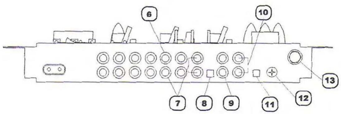
Rear Panel Description and Functions cont...
- AV2 (DVD) INPUT jacks - These jacks are for connecting an AV device such as a DVD player. NOTE: The corresponding VIDEO jack (YELLOW) is located leftward in the VIDEO INIOUT area. The AV2 VIDEO IN jack is surrounded by a GRAY colored painted region.
- CD2/PH2 INPUT jack - This jack is for connecting either a line-level AUDIO device such as a CD player or a PHONO/TURNTABLE, NOTE: The CD2/PH2 TOGGLE button must be set to PH2 for a PHONO/TURNTABLE device or CD2 for a line-level AUDIO DEVICE for proper functioning.
- CD2/PH2 TOGGLE button - This button toggles between LINE-LEVEL and PHONO signal compatibility for the corresponding CD2/PH2 INPUT jacks.
- AV1 (VCD) INPUT jack - This jack is for connecting an AV device such as a VCD player. NOTE: The corresponding VIDEO jack (YELLOW) is located leftward in the VIDEO IN/OUT area. The AV1 VIDEO IN jack is surrounded by a WHITE colored painted region.
- CD1/PH1 INPUT jacks - These jacks are for connecting either a line-level AUDIO device such as a CD player or a PHONO/TURNTABLE, NOTE: The CD1/PH1 TOGGLE button must be set to PH1 for a PHONO/TURNTABLE device or CD1 for a line-level AUDIO DEVICE for proper functioning.
- CD1/PH1 TOGGLE button - This button toggles between LINE-LEVEL and PHONO signal compatibility for the corresponding CD1/PH1 INPUT jacks.
- GROUND terminal - This TERMINAL is for connecting a ground wire to other devices in the AUDIO SYSTEM chain. If you are experiencing line noise, attach wire from this TERMINAL to your other devices or similar suitable surface.
- MIC 2 INPUT jack - This ¼" jack is used to connect a MICROPHONE with a ¼" style plug.
Rear Panel
Operations
Digital Key Control
Using Digital Key Control
Use the Digital Key Controller to obtain the desired musical key (24 steps). The Digital Key Controller indicators LED display the selected key. To step UP, slide the JOG DIAL counter-clockwise. To step DOWN, slide the JOG DIAL clockwise. To revert back to the original key, press the JOG DIAL.
Assigning Digital Key Control to Microphone and Line Channels
Once you have attained a desired key, you can assign the key changes to the channels you desire. To ASSIGN, you simply press the KEY button located to the right of the fader on each channel you want the key changes to be applied to (both MIC and line) and the key changes will take immediate effect. To REMOVE a key change from a channel, simply depress the KEY button from that channel, and it is removed.
Digital Echo
Customizing Digital Echo settings
When using Digital Echo, you can customize the effect by adjusting the ECHO, REPEAT and DELAY controls. First set the ECHO level control to 5. Then customize the effect with the REPEAT and DELAY level controls. REPEAT adjusts the interval repetition of the echo effect. As more REPEAT is applied, more echo intervals will be heard when using it and vice versa. DELAY adjusts length of each interval. As more DELAY is applied, there will be more "space" between the starting and ending point of each echo. When the Digital Echo effect is customized, adjust the ECHO level control as you would a master level control.
Vocal Cancel/Partner/Elimination
Utilizing Vocal Cancel Modes
VOCAL CANCEL will cancel out the vocal layer of a track on multiplexed Karaoke media, while letting the background music through. VOCAL PARTNER mode is similar to an "auto-pilot" mode. In this mode, the vocal layer will be cancelled only as long there is Mic activity present. When there is no Mic activity present, the vocal layer is brought back in. In other words, when you are singing, the vocal layer is cancelled. And when you are not singing, the vocal layer is brought back in. This mode is commonly used when a solo singer wants to sing a duet, as the "other singer" comes in automatically. Vocal Elimination cancels lead vocals from standard CD's. Remember that this feature will work differently with each disc as the recording technique used differs from CD to CD.
Graphic EQ
Fine tuning music for precise room tuning
To fine tune the sound of your musical output, we included the 5-Band Graphic EQ. This EQ makes adjusting the warmth or sharpness of your music a breeze.
Cueing
Channel Cueing
Channel cueing monitors the input signal(s) from the mix board to the headphones. When channel cueing, you can select as many channels as you like to cue to headphones. To CUE, first make sure the MASTER2/CUE SELECTOR button is set to CUE. Then press the CUE button on each channel that you want cued to the headphones. To REMOVE a channel from being cued, simply depress that channels CUE button. To INCREASE or DECREASE the volume level to headphones, use the Master2/CUE LEVEL control.
Master Cueing
Master Cueing will cue the MASTER OUTPUT to the headphones. This is commonly used to isolate the audio signal to the headphones. Master cueing makes it possible to practice when "audible" music is not permitted i.e. late night practicing at home. To MASTER CUE, make sure the CUE/MASTER button is set to MASTER and adjust the CUE LEVEL control to a desired volume level.
Crossfader
Crossfading between sources
The crosslader allows you to "mix" or crossfade between two channels. Slide the CROSSFADER back and forth to crossfade between source channels
Video Selector
Switching Between Video Channels
If you have more than one A/V source connected, and would like to switch video channels for output to a display device, you would use the VIDEO SELECTOR toggle switch. The switch will toggle between A/V CHANNELS 1 and 2.
Record
Recording a Performance or Mix
To RECORD a mix or performance, connect a line-level patch cable from the RECORD OUT to the AUDIO IN of a recording device.
- VocoPro
- Features:
- KJ-6000
- Safety Instructions
- CAUTION
- RISK OF SHOCK
- Explanation of Graphical Symbols
- WARNING
- Note:
- FCC INFORMATION (U.S.A.)
- IMPORTANT NOTICE: DO NOT MODIFY THIS
- CAUTION:
- READ THIS BEFORE OPERATING YOUR UNIT
- FOR YOUR RECORDS
- Digital Karaoke Mixer with Digital Key Control
- Contents
- Introduction
- Before Getting Started
- Getting Connected
- Controls and Functions
- Operations
- Specifications
- INPUTS:
- OUTPUTS:
- MICROPHONE TONE CONTROL:
- MASTER EQUALIZER:
- NOISE RATIO:
- Listening For A Lifetime
- To establish a safe level:
- Once you have established a comfortable sound level:
- Unpacking the KJ-6000
- Parts
- Mounting the KJ-6000
- Top Mounting
- Installation
- Connecting Phono Sources
- Connecting Line-level Audio Sources (CD Player, MP3 Players, etc.)
- Getting Connected cont...
- Connecting A/V Sources (CDG, DVD, VCD Players, etc.)
- A/V Sources
- Connecting Video Output to a TV
- Video to TV
- Connecting Output to an External Sound System, Mixer or Recording Device
- Connecting Microphones to the KJ-6000
- Microphone Channel Controls and Functions
- Stereo Panel Controls and Functions
- Master Panel Controls and Functions
- Master Panel Controls and Functions cont...
- Front Panel Description and Functions
- Front Panel
- Rear Panel Description and Functions
- Rear Panel
- Rear Panel Description and Functions cont...
- Digital Key Control
- Digital Echo
- Vocal Cancel/Partner/Elimination
- Graphic EQ
- Cueing
- Crossfader
- Video Selector
- Record
Mærke : Vocopro
Model : KJ-6000
Kategori : Karaoke