Hydromassage Shower Cabin - Brusekabine Aqualine - Gratis brugsanvisning og manual
Find enhedens vejledning gratis Hydromassage Shower Cabin Aqualine i PDF-format.

Brugerspørgsmål om Hydromassage Shower Cabin Aqualine
0 spørgsmål om dette apparat. Besvar dem du kender, eller stil dit eget.
Stil et nyt spørgsmål om dette apparat
Download vejledningen til din Brusekabine i PDF-format gratis! Find din vejledning Hydromassage Shower Cabin - Aqualine og tag din elektroniske enhed tilbage i hånden. På denne side er alle dokumenter nødvendige for brugen af din enhed offentliggjort. Hydromassage Shower Cabin af mærket Aqualine.
BRUGSANVISNING Hydromassage Shower Cabin Aqualine
Product Specification
Height: 2110mm x Depth: 900mm x Width: 800mm
Minimum pressure requirement: of 1.5 bar
Door Opening Size: 480mm
Thermostatic valve with diverter
Multi Mode Hand shower with slide rail
Acrylic shower tray with push button waste and adjustable feet
Cleaning
The product should be cleaned using a soft damp cloth, no abrasive agents or materials must be used, or this will invalidate your guarantee.
Please visit our website to view a installation video product code 8254
Aqualine Hydromassage Shower Cabin
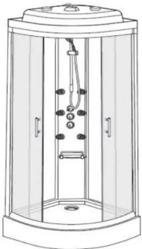
natural_image
Line drawing of a shower enclosure with doors, wheels, and a central handle (no text or symbols)Please retain this manual after installation for future reference and maintenance.
Product must be installed in compliance with relevant Water Bylaws
Parts
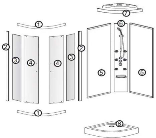
Part
| 1 | Top and bottom rail | 1 Pair |
| 2 | Fixed panel profile | 2 |
| 3 | Fixed front panel | 2 |
| 4 | Door | 2 |
| 5 | Back Panel (Coloured) | 2 |
| 6 | Shower control panel | 1 |
| 7 | Cabin Roof | 1 |
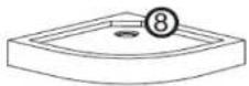
| 8 | Shower tray | 1 |
Parts
Part
| Description | Qty |
| Overhead shower and nut | 1 |
| Hand shower | 1 |
| Shower hose inc seal | 1 |
| Slide rail | 1 |
| Glass shelf and brackets | 1 |
| Top fixed roller | 4 |
| Bottom spring roller | 4 |
| Glass retaining clip | 4 |
| Roller stop | 8 |
| Back panel screws | 10 |
| Magnetic door seals | 2 |
| Fixed panel seal | 2 |
| Door seal | 2 |
| Profile gasket seal | 2 |
| Door handle | 2 |
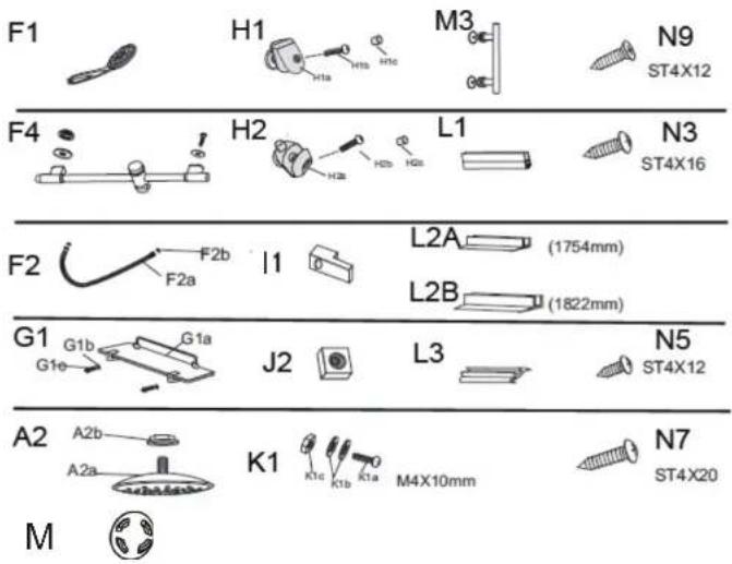
| Part | Description | Qty |
| N3 | Back panel/frame screws | 30 |
| N5 | Roller stop screw | 8 |
| N7 | Rail screws | 8 |
| N9 | Retaining clip screws | 4 |
| M | Cover | 4 |
Tools required
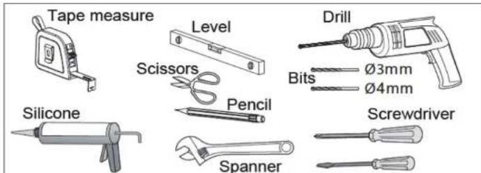
If installing on a tray, follow correct method of installation by installing the tray and tile down onto this.
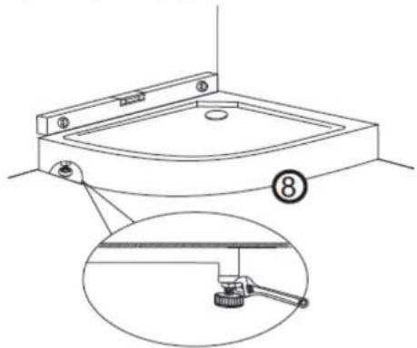
Installation - Step 1
Access will be required to the rear during assembly!
Lay the shower tray in the required location, this should be checked for level and if any adjustment is required, adjust the legs underneath the tray.
Once the tray is level and at the required height the legs should be secured by tightening the locking nut, using a spanner.
BB INST 8254 ISSUE 1
Installation - Step 2
Once the tray has been adjusted and the legs secured, the waste flexi pipe should be connected to the domestic drainage system and checked for water tightness before full assembly is completed.
natural_image
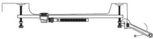
Technical line drawing of a mechanical clamp or support structure (no text or symbols)Installation - Step 3
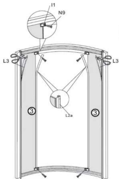
Connect the top and bottom rails (1) to the side profiles (2) using the screws (N7) ST4 x 20 Fit the screws through the side profile to connect to the rails.
Installation - Step 4
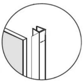
Place the front glass panels (3) into the side profiles, ensuring these are fully inserted push in the glass gasket (L3) between the profile and the glass and push in fully to secure the glass, cut down to suit.
Fit glass seal (L2A) onto front panel with the fin facing inwards.
Secure the glass to the frame using the glass retaining clips (I1) and screws (N9) ST4 x 12
natural_image
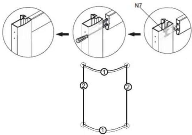
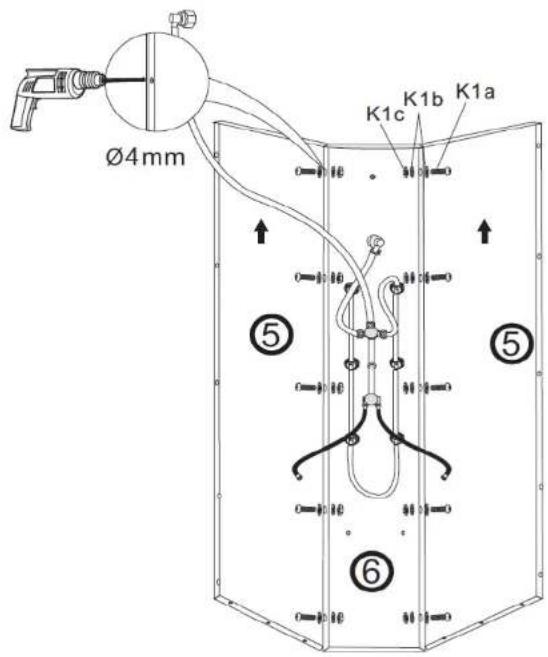
Simple line drawing of two vertical panels inside a circle (no text or symbols)Installation - Step 5
Place the rear panels (5) and the centre shower control panel (6) together.
Once these are correctly aligned, drill the frame at the rear using a 4mm drill bit.
Drill the frame in five positions equally spaced along the join.
Before screwing these together we recommend sealing each join to create a watertight seal.
Secure the panels together using fixing bolts K1 (K1A-K1B,K1C)
Please make sure this glass panels (5) arrow up"
BB INST 8254 ISSUE 1
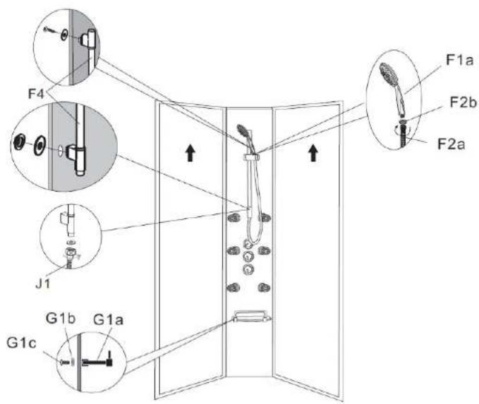
Installation - Step 6
Offer the slide rail (F4) to the centre panel holes and secure the bottom bracket/outlet to the panel using the washer and nut provided.
Secure the top rail bracket to the panel using the screw and washer provided and tighten all connections.
Ensure the washers are fitted to each end of the shower hose and connect the nut end to the slide rail outlet.
Next connect the cone end of the hose to the hand shower, again tighten.
Secure the glass shelf to the panel using the screws and washers provided.
BB INST 8254 ISSUE 1
Installation - Step 7
This part of the assembly may require two people.
Place the panels and the frame onto the shower tray, we recommend sealant is applied between the panels, frame and the tray.
Once positioned correctly, drill the tray and frame using a 3mm drill bit and secure together using screws (N3) ST4 x16
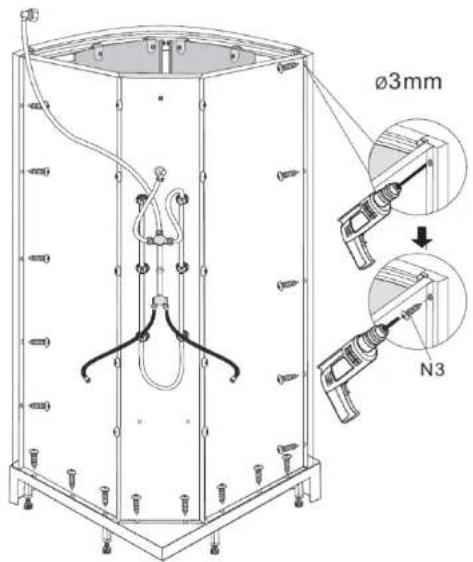
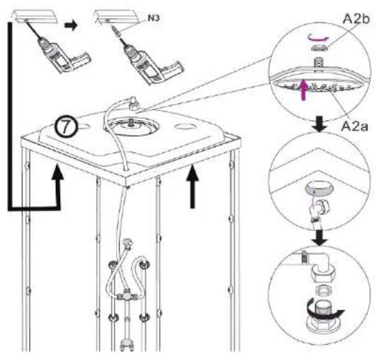
Installation - Step 8
Place the roof (7) onto the frame and align.
Drill the frame and roof from the underside using a 3mm drill bit and secure roof to frame using screws provided (N3) ST4X16
Pass the long hose and elbow for the overhead through the hole in the roof.
From inside the enclosure pass the threaded connector on the overhead shower (A2A), through the roof and secure into position, using the nut provided (A2B).
Next connect the pipe elbow to the threaded connector on the overhead shower and ensuring the seal is fitted, tighten.
88 INST 8254 ISSUE 1
Installation - Step 9
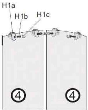
IMPORTANT - FIXED ROLLERS FITTED TO TOP
To fit the top (Fixed - H1) rollers, offer the roller to the door and connect through the glass using the screw provided, tighten and fit cover cap.
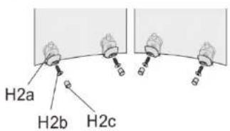
Fit the spring loaded rollers (H2) to the bottom of the door Secure them to the door using the screws and covers provided Hook the door onto the top rail, then push the door towards the bottom rail.
Push down on the button and hook under bottom rail, then release.
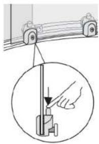
natural_image
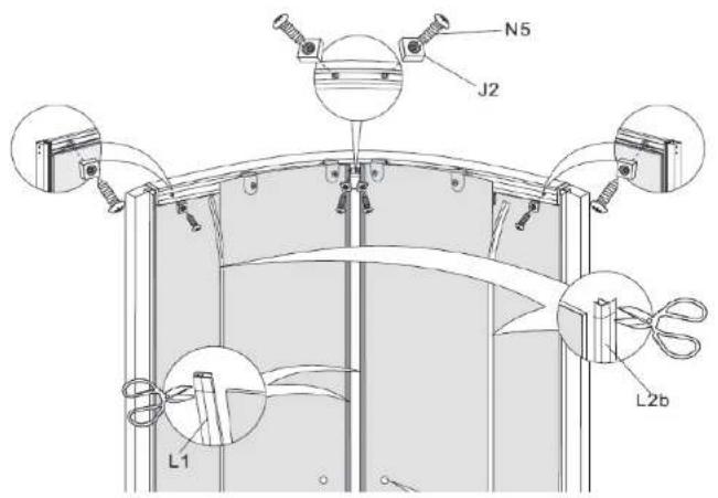
Diagram showing a hand operating a mechanical device with a magnified inset (no text or symbols)Installation - Step 10
Once the doors are installed, the door stops (J2) need to be fitted.
Secure these to the frame using the screws provided (N5)
Fit the magnetic door seals (L1) to the edge of the door.
The door seals (L2B) should be fitted to the doors, as shown below with the fin facing outward from the tray.
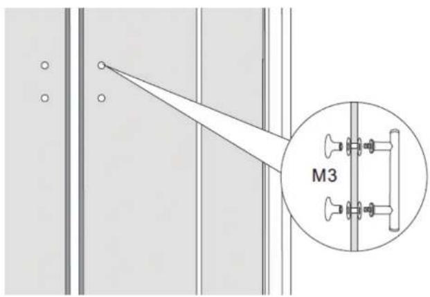
Installation - Step 11
Offer the door handle (M3) up to the holes in the doors, connect the handle through the glass and tighten using fittings supplied.
BB INST 8254 ISSUE 1
Installation -Step 12
Put the covers in profile sholes.
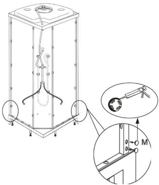
Installation -Step 13
The next step is to seal the outside of the enclosure.
Once sealed do not sue for at least 24 hrs.
Finally before positioning the enclosure in its required location, the flexi supply pipes on the rear should be connected to the water supply pipes.
Hot on left - Cold on right.
Note: Incoming pressures must be balanced.
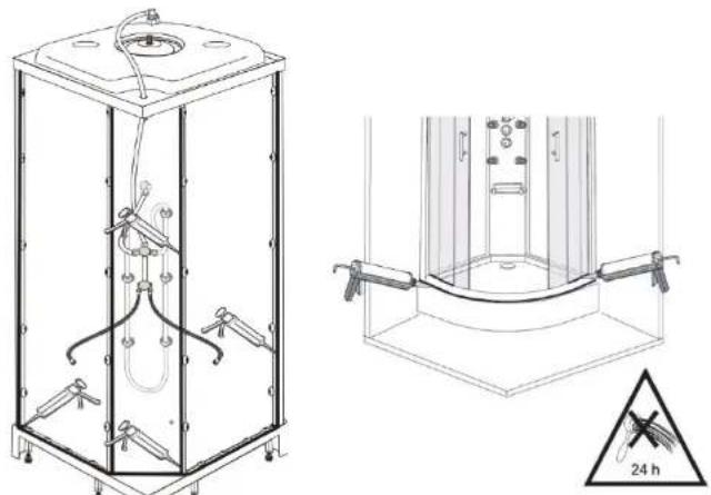
natural_image
Technical line drawing of a mechanical device with internal components and a 24-hour warning symbol (no text or labels)Guarantee
Not covered by the guarantee is:
Breakdown due to -
a) Use other than domestic
b) Wilful act of neglect
c) Any malfunction resulting from incorrect use
d) Incorrect setting of controls
e) Any malfunction resulting from poor water quality
• Repair costs for damage caused by foreign objects or substances
• Total loss of the product due to non-availability of parts
• Compensation for loss of use of the product or consequential loss of any kind.
- Call out charges where no fault has been found with the product.
Not covered by the guarantee is:
- The cost of repair or replacement of pressure relief devices, spray heads, hoses, riser rails and/or wall bracket or any other accessories installed at the same time.
- The cost of routine maintenance, adjustments, overhaul, modifications, loss or damage, arising therefrom, including the cost of repairing damage, breakdown, malfunction caused by corrosion, furring, pipe scaling, lime scale, system debris or frost.
Mærke : Aqualine
Model : Hydromassage Shower Cabin
Kategori : Brusekabine