
SCN60PA1SU - Ismaskine Scotsman - Gratis brugsanvisning og manual
Find enhedens vejledning gratis SCN60PA1SU Scotsman i PDF-format.

Brugerspørgsmål om SCN60PA1SU Scotsman
0 spørgsmål om dette apparat. Besvar dem du kender, eller stil dit eget.
Stil et nyt spørgsmål om dette apparat
Download vejledningen til din Ismaskine i PDF-format gratis! Find din vejledning SCN60PA1SU - Scotsman og tag din elektroniske enhed tilbage i hånden. På denne side er alle dokumenter nødvendige for brugen af din enhed offentliggjort. SCN60PA1SU af mærket Scotsman.
BRUGSANVISNING SCN60PA1SU Scotsman
SCN60
Service Parts
This is the illustrated parts list for the SCN60.
There are two models, one is a gravity drain and the other includes a drain pump. Some units could have had drain pumps field installed.
Table of Contents
| Door Components | Page 2 |
| Cabinet | Page 3 |
| Storage Bin and Ice Chute | Page 4 |
| Reservoir, Water Sensor and Misc | Page 5 |
| Refrigeration | Page 6 |
| Under Bin Parts | Page 7 |
| Ice Making Section | Page 8 |
| Control System | Page 9 |
| Wiring Diagram | Page 10 |
| Schematic Diagram | Page 11 |
Service Parts
Door Components
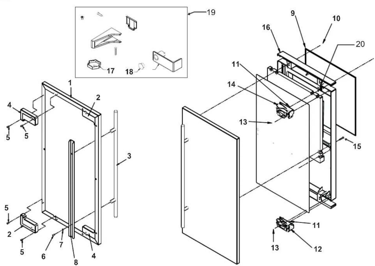
Item Part
Number Number Description
1 Door panel kit. Kit includes items 1 thru 8.
KDFS SS panel, SS handle
2 02-4433-01 Corner block, RH
3 02-4430-01 Handle, SS
4 02-4433-02 Corner block, LH
5 03-1531-01 Screw
6 03-3811-01 Screw
7 03-1410-07 Lockwasher
8 A39390-001 Support bracket
9 13-0949-03 Door gasket
10 03-1404-40 Screw
11 03-3818-01 Screw - hinge to cabinet
12 02-3866-04 Hinge - top right/bottom left
13 03-1404-24 Screw - hinge to door
14 02-3866-03 Hinge
15 03-1403-67 Screw
16 A39513-001 Door assembly, does not include door panel or hinges
17 02-4415-20 Leg cap, pack of 4
18 02-1875-07 Hole plug
19 02-4474-01 Hinge package
20 11-0580-01 Magnet, door switch
Service Parts
Cabinet
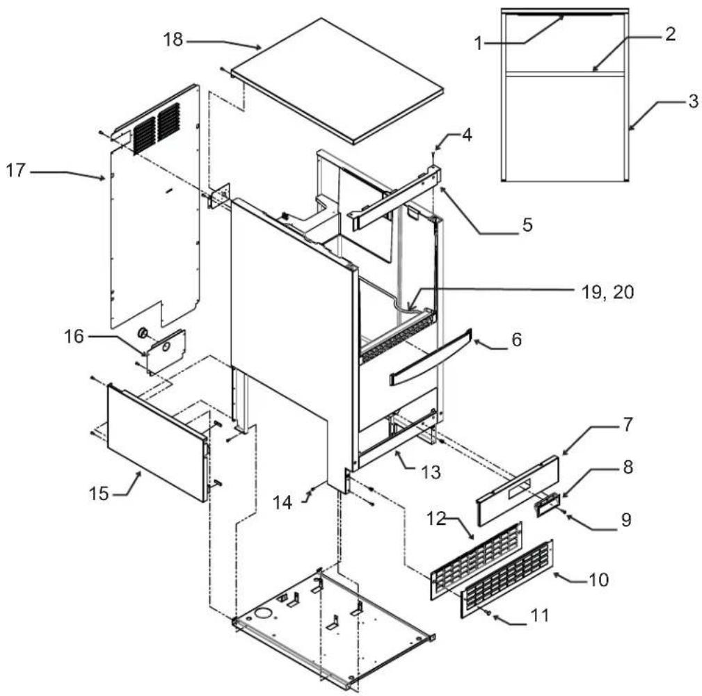
Item Part
Number Number Description
1 13-0943-03 Gasket, top panel
2 13-0943-04 Gasket, top panel
3 13-0943-05 Gasket, top panel
4 03-3836-03 Screw
5 A39364-003 Top hinge bracket, hinge right A39364-007 Top hinge bracket, hinge L or R
6 02-4392-01 Inlay
7 A39381-003 Front service panel
8 02-4441-01 Handle
9 03-1403-86 Screw
10 A39469-001 Kick plate cover
11 03-3813-02 Screw
12 02-4390-01 Kick plate
13 A39385-003 Bottom hinge bracket, hinge L or R A39385-006 Bottom hinge bracket, hinge left
14 03-1531-01 Screw
15 A39615-001 Side service panel
16 A39683-001 Drain panel
17 A39682-001 Back panel
18 A39362-003 Top panel only
18a 02-4426-01 Insulation, top panel
19 A34816-001 Bin stat bracket
20 02-4391-03 Scoop
Note: Hinge mounting changed 1/12 to allow left or right mounting.
Service Parts
Storage Bin and Ice Chute
Item Part
Number Number Description
1 03-1405-16 Screw, 5/16-18
2 02-4628-01 Ice sweep
3 02-4537-21 Chute
4 Chute insulation, part of item 3
5 03-1404-41 Screw
6 03-3935-01 Grommet
7 03-3936-01 Flanged bushing
8 03-1405-07 Cap screw
9 03-3937-01 Vibration grommet
9a 03-1407-06 Washer
10 A39681-001 Mounting plate only
11 02-4582-01 Shelf, gear and evap asy
12 A39782-001 Drain
13 13-0840-01 Drain plug
14 03-3892-01 Thumb screw
15 02-4585-21 Cover
16 Cover insulation, part of item 15
17 02-4375-02 Support bracket, left 02-4375-01 Support bracket, right
18 03-3836-03 Screw
19 02-4572-01 Tube, reservoir to evap
Service Parts
Reservoir, Water Sensor and Misc
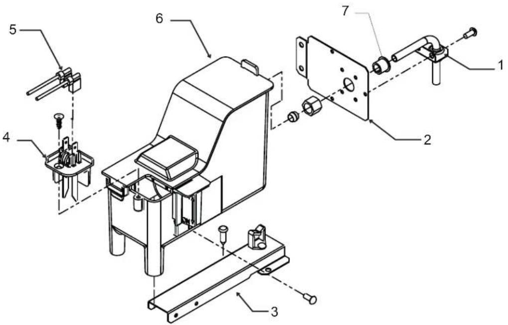
Item Part
Number Number Description
1 A39826-001 Brace
2 A39693-001 Bracket
3 A39775-001 Reservoir mounting bracket
4 A39790-001 Water level sensor
5 12-3039-01 Water sensor harness
6 A39789-001 Reservoir w/valve and cover
6a 02-2217-02 Float and valve only
Misc:
1m 19-0664-01 Pre-Mixed Squirt Bottle of Clear 1 scale remover
2m 19-0664-12 12 pack of item 1m
3m 19-0653-12 Case of undiluted Clear 1 scale remover
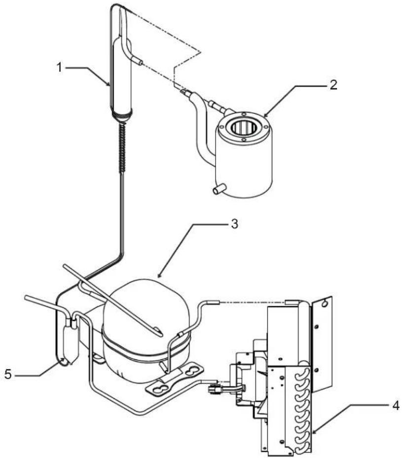
Item Part
Number Number Description
1 A39396-001 Suction line w/cap tube
2 02-4558-01 Evaporator
3 18-8776-21 Compressor
Compressor includes overload, relay and drier
3a 18-8776-52 Overload
3b 18-8776-51 Relay
4 18-8940-01 Condenser
5 02-3490-01 Dryer
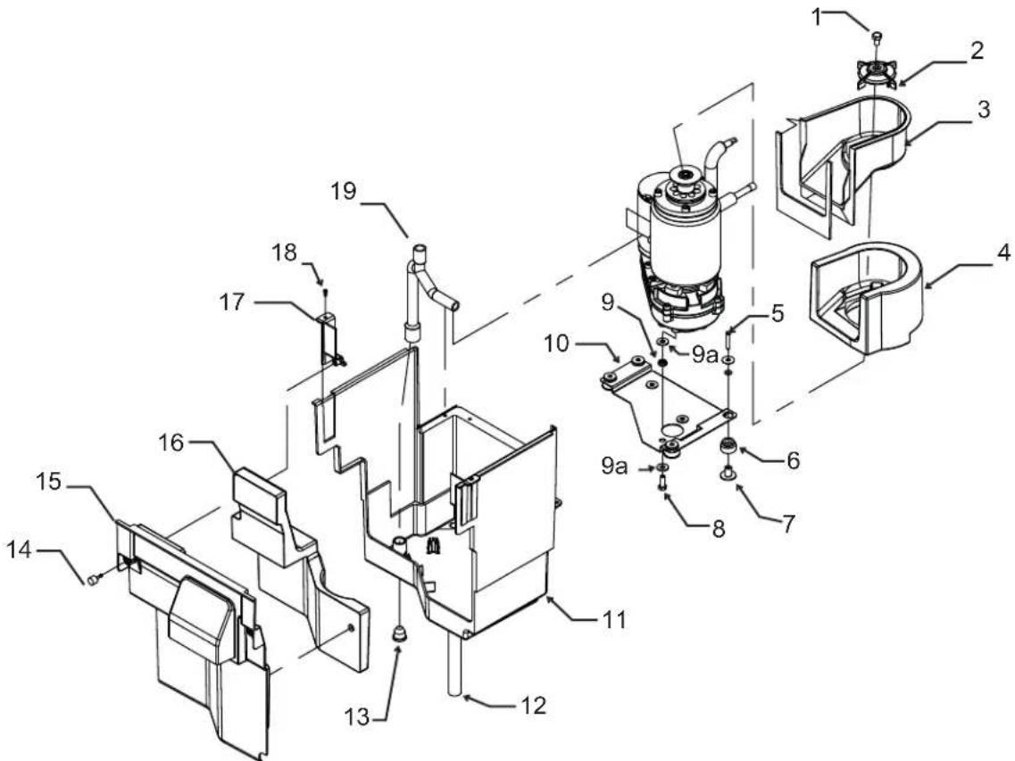
Service Parts
Under Bin Parts
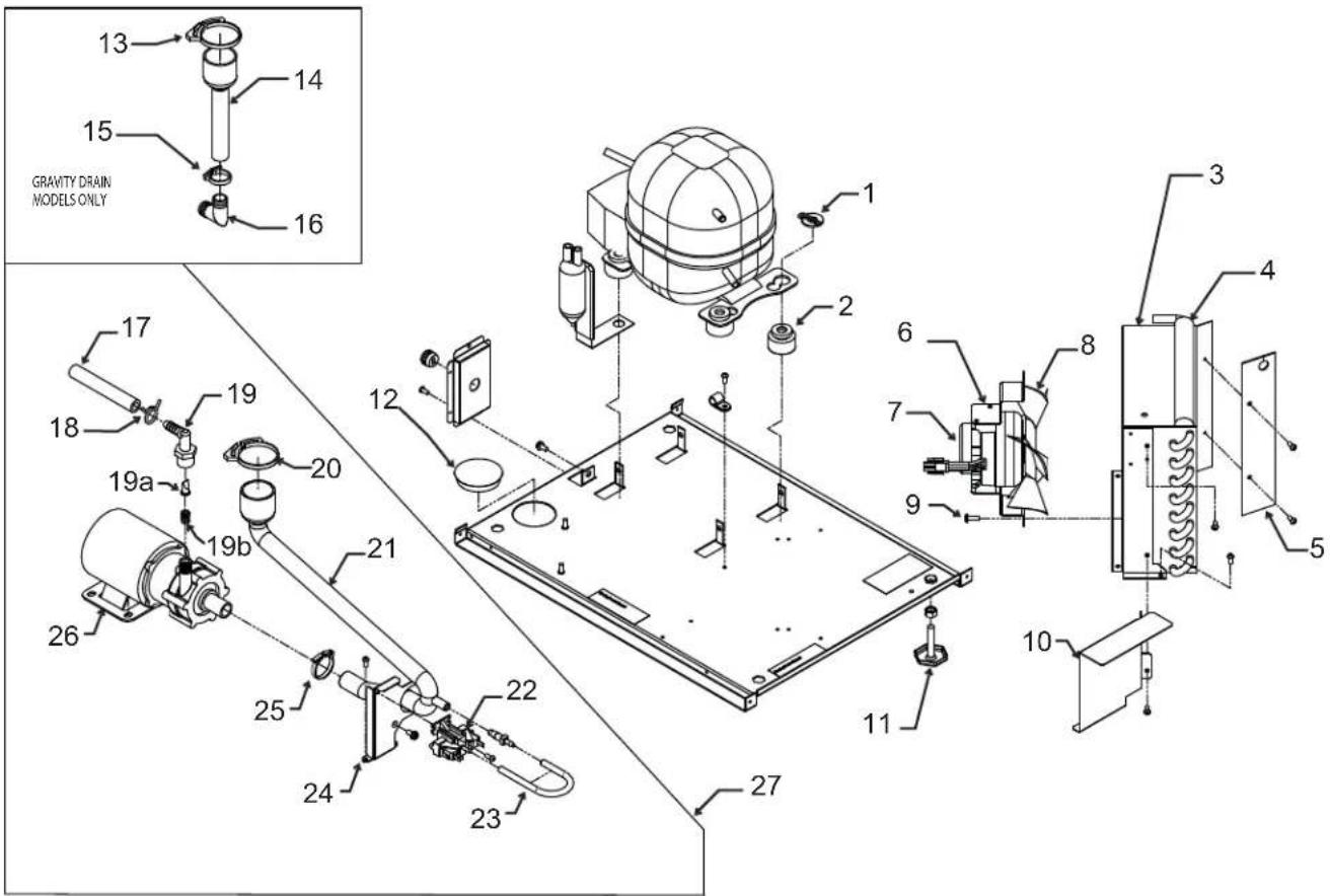
Item Part
Number Number Description
1 03-3821-01 Clip
1a 03-1407-08 Washer
2 18-4700-28 Grommet
3 A39460-001 Shroud
4 13-0909-01 Gasket - order 1 & cut to fit
5 02-4450-01 Air baffle
6 A39556-001 Fan motor bracket
7 12-3024-01 Fan motor
8 02-4197-01 Fan blade
9 03-3818-01 Screw
10 A39825-001 Pump model rain shield
11 03-1608-01 Leg leveler
12 02-1875-18 Hole plug
13 02-2814-13 Hose clamp
14 02-4412-01 Drain hose
15 02-2814-08 Hose clamp
16 16-0671-01 Elbow
17 A37334-001 Discharge hose
18 02-0534-02 Hose clamp
19 02-3522-01 Elbow
19a 02-3374-01 Check valve
19b 03-3904-01 Spring
20 02-2814-13 Hose clamp
21 02-4413-01 Drain tube
22 11-0504-01 Pressure switch
23 05-0591-01 Switch hose
24 A39370-001 Switch bracket
25 02-2814-13 Hose clamp
26 12-2503-21 Pump & motor only
27 A39462-021 Pump kit
Service Parts
Ice Making Section
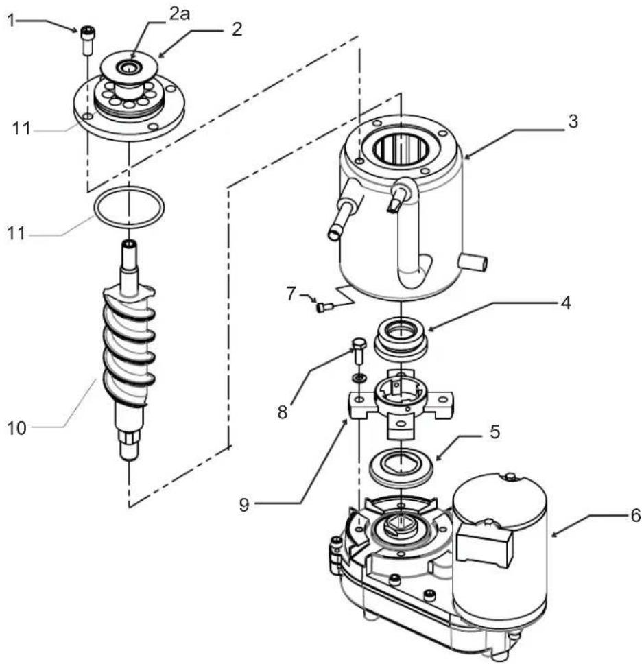
Item Part
Number Number Description
1 03-1544-08 Cap screw
2 A39531-001 Breaker w/bearing
2a 02-4619-01 Bearing only
3 02-4558-01 Evaporator
4 02-4599-21 Water seal
5 02-4662-01 Water shed
6 02-4580-21 Gear reducer complete
7 03-1544-04 Cap screw
8 03-1405-54 Cap screw
9 02-4625-01 Adapter
10 02-4591-21 Auger
11 13-0617-58 O-ring
* Must connect wires correctly. See label on motor.
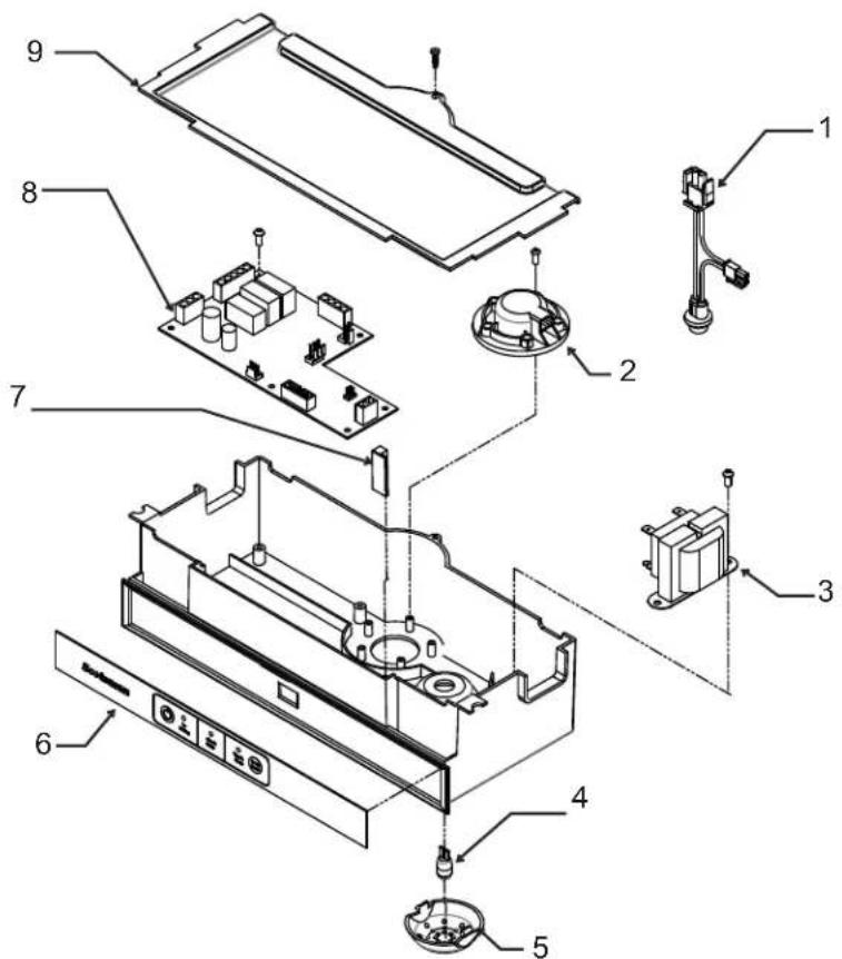
Item Part
Number Number Description
1 12-2980-02 Harness, bin light
2 11-0579-01 Ice level sensor
3 12-2924-01 Transformer
4 12-2980-01 Bulb
5 02-4380-01 Light cover
6 11-0574-01 Control panel
7 12-2980-03 Bin light switch
8 11-0589-21 Controller
9 02-4386-01 Cover
Service Parts
Wiring Diagram
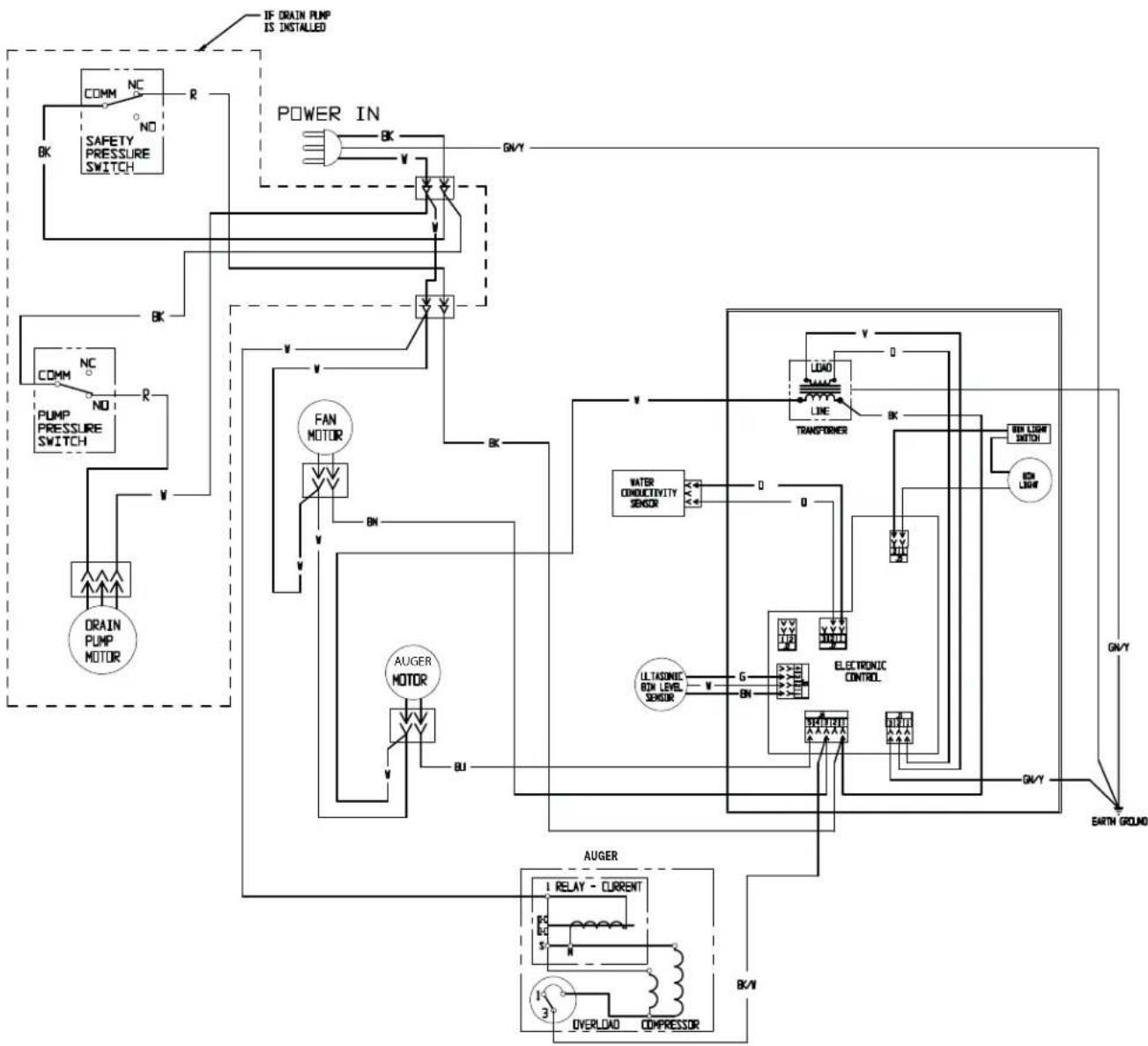
flowchart
graph TD
    A["IF DRAIN PUMP IS INSTALLED"] --> B["POWER IN"]
    B --> C["SAFETY PRESSURE SWITCH"]
    C --> D["COMM NC"]
    D --> E["BK"]
    E --> F["PUMP PRESSURE SWITCH"]
    F --> G["CONN NC"]
    G --> H["BK"]
    H --> I["FAN MOTOR"]
    I --> J["DRAIN PUMP MOTOR"]
    I --> K["AUGER MOTOR"]
    K --> L["ULTASONIC BOX LEVEL SENSOR"]
    L --> M["ELECTRONIC CONTROL"]
    M --> N["LOAD LINE TRANSFORMER"]
    N --> O["ON LIGHT SWITCH"]
    O --> P["ON LIME"]
    P --> Q["EARTH GROUND"]
    Q --> R["Ground"]
    style A fill:#f9f,stroke:#333
    style B fill:#ccf,stroke:#333
    style C fill:#cfc,stroke:#333
    style D fill:#fcc,stroke:#333
    style E fill:#cff,stroke:#333
    style F fill:#ffc,stroke:#333
    style G fill:#cfc,stroke:#333
    style H fill:#fcc,stroke:#333
    style I fill:#ffc,stroke:#333
    style J fill:#cfc,stroke:#333
    style K fill:#fcc,stroke:#333
    style L fill:#ffc,stroke:#333
    style M fill:#cfc,stroke:#333
    style N fill:#fcc,stroke:#333
    style O fill:#ffc,stroke:#333
    style P fill:#cfc,stroke:#333
    style Q fill:#fcc,stroke:#333
    style R fill:#ffc,stroke:#333
    style S fill:#cfc,stroke:#333
    style T fill:#fcc,stroke:#333
    style U fill:#ffc,stroke:#333
    style V fill:#cfc,stroke:#333
    style W fill:#fcc,stroke:#333
    style X fill:#ffc,stroke:#333
    style Y fill:#cfc,stroke:#333
    style Z fill:#fcc,stroke:#333
Service Parts
Schematic Diagram
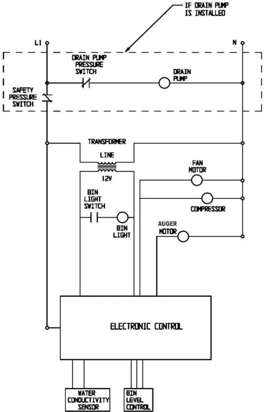
flowchart
graph TD
    A["LI"] --> B["DRAIN PUMP PRESSURE SWITCH"]
    B --> C["DRAIN PUMP"]
    C --> D["N"]
    E["SAFETY PRESSURE SWITCH"] --> F["TRANSFORMER LINE"]
    F --> G["12V"]
    G --> H["BIN LIGHT SWITCH"]
    H --> I["BIN LIGHT"]
    I --> J["ELECTRONIC CONTROL"]
    K["FAN MOTOR"] --> L["COMPRESSOR"]
    M["AUGER MOTOR"] --> N["COMPRESSOR"]
    O["WATER CONDUCTIVITY SENSOR"] --> P["ELECTRONIC CONTROL"]
    Q["BIN LEVEL CONTROL"] --> P
    R["IF DRAIN PUMP IS INSTALLED"] --> S["OUT"]
    style A fill:#f9f,stroke:#333
    style B fill:#ccf,stroke:#333
    style C fill:#cfc,stroke:#333
    style D fill:#fcc,stroke:#333
    style E fill:#cff,stroke:#333
    style F fill:#ffc,stroke:#333
    style G fill:#cfc,stroke:#333
    style H fill:#cfc,stroke:#333
    style I fill:#cfc,stroke:#333
    style J fill:#cfc,stroke:#333
    style K fill:#fcc,stroke:#333
    style L fill:#cfc,stroke:#333
    style M fill:#cfc,stroke:#333
    style N fill:#cfc,stroke:#333
    style O fill:#fcc,stroke:#333
    style P fill:#cfc,stroke:#333
    style Q fill:#fcc,stroke:#333
    style R fill:#cfc,stroke:#333
SWITCHES ON THIS UNIT
SHOWN IN FREEZE CYCLE
WITH DRAIN PUMP IN OPERATION
AND BIN DOOR CLOSED
Mærke : Scotsman
Model : SCN60PA1SU
Kategori : Ismaskine