
BK650EI - Server APC - Gratis brugsanvisning og manual
Find enhedens vejledning gratis BK650EI APC i PDF-format.


Brugerspørgsmål om BK650EI APC
0 spørgsmål om dette apparat. Besvar dem du kender, eller stil dit eget.
Stil et nyt spørgsmål om dette apparat
Download vejledningen til din Server i PDF-format gratis! Find din vejledning BK650EI - APC og tag din elektroniske enhed tilbage i hånden. På denne side er alle dokumenter nødvendige for brugen af din enhed offentliggjort. BK650EI af mærket APC.
BRUGSANVISNING BK650EI APC
Installation

www.apc.com
Back-UPS™ CS
350/500/650
User's Manual
990-9237 3/04
1 Placement / Power
Avoid placing the Back-UPS in:
- Direct sunlight
- Excessive heat
- Excessive humidity or in contact with fluids of any type

Plug the Back-UPS into a wall outlet, as shown.
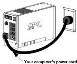
text_image
APC Your computer's power cord.• The Back-UPS charges the internal battery any time it is connected to a wall outlet.
2 Connect Equipment to the Back-UPS
The rear panel of the Back-UPS consists of the following elements:
Battery Back Up Outlets (qty. of 3). These outlets provide battery back-up, surge protection, and Electro-magnetic Interference (EMI) filtering. In case of power outage, battery power is automatically provided to these outlets. Power (utility or battery) is not supplied to these outlets when the Back UPS is switched Off. Connect a computer, monitor, and external disk or CD-ROM drive to these outlets.
Surge Only Outlet. This outlet is always On (when utility power is available) and is not controlled by the On/Off switch. This outlet does not provide power during a power outage. Connect a printer, fax machine or scanner to this outlet.

text_image
Diagram showing connections between a computer, tower, and printer with an MPC device labeled 'RPC'3 Connect the Phone Line to Surge Protection
The telephone ports provide lightning surge protection for any device connected to the telephone line (computer, modem, fax or telephone). The telephone ports are compatible with Home Phoneline Networking Alliance (HPNA) and Digital Subscriber Line (DSL) standards, as well as all modem data rates. Connect as shown.
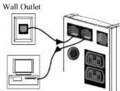
flowchart
graph TD
    A["Wall Outlet"] --> B["Device 1"]
    A --> C["Device 2"]
    B --> D["Button 1"]
    C --> E["Button 2"]
Modem/Phone/Fax
4 Switch on the Back-UPS
Note: Allow the Back-UPS to charge for a full eight hours prior to use.
Press the push-button on the front panel of the Back-UPS.
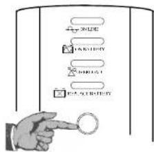
text_image
INPUT INSERT DIRECT OUTPUTObserve that the following events occur after pressing and releasing the push-button:
• The green On-Line indicator flashes.
• The yellow On Battery indicator lights while the Self-Test is being performed.
- When Self-Test has successfully completed, only the green On Line indicator will be lit.
- If the internal battery is not connected, (see Step 1 above) the green On Line indicator and red Replace Battery indicator will light. The BackUPS will also emit a chirping sound.
5 Connect USB Cable and Install Software (optional)
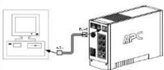
text_image
Diagram showing connection between an MPC device and a computer interface, with labeled ports and signal paths.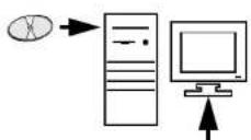
Follow the
on-screen instructions
instructions
NOTE: Macintosh Users - for full USB performance, use Mac OS 10.1.5 or higher.
If Autoplay is not enabled on the computer, proceed as follows:
- On the computer desktop of the display, double-click on My Computer.
- Double-click on the CD-ROM drive icon and follow the on-screen instructions.
Status Indicators and Alarms
There are four status indicators (lights) on the front panel of the Back-UPS (On Line, On Battery, Overload, and Replace Battery).
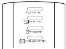
On Line (green) - is lit whenever utility power is powering the Battery Backup outlets.
On Battery (yellow) - is lit whenever the battery of the Back-UPS is powering equipment connected to the Battery Backup Outlets.
Four Beeps Every 30 Seconds - this alarm is sounded whenever the Back-UPS is running On Battery. Consider saving work in progress.
Continuous Beeping - this alarm is sounded whenever a low battery condition is reached. Battery run-time is very low. Promptly save any work in progress and exit all open applications. Shutdown the operating system, computer and the Back-LPS.
Overload (red) - is lit whenever power demand has exceeded the capacity of the Back-UPS.
Continuous Tone - this alarm is sounded whenever the Battery Backup outlets are overloaded.
Circuit Breaker - the circuit breaker button located on the rear panel of the Back-UPS will stick out if an overload condition forces the Back-UPS to disconnect itself from utility power. If the button sticks out, disconnect non-essential equipment. Reset the circuit breaker by pushing the button inward.
Replace Battery (red) - is lit whenever the battery is near the end of its useful life, or if the battery is not connected (see above). A battery that is near the end of its useful life has insufficient run-time and should be replaced.
Chirps for 1 Minute Every 5 Hours - this alarm is sounded whenever the battery has failed the automatic diagnostic test.
Replace the Internal Battery
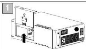
To replace the internal battery, proceed as follows:
Note: Replacing the battery is a safe procedure. However, small sparks may occur during the process. This is normal.
text_image
1 9Place the unit on its side. Slide the battery compartment cover upward and off of the UPS.
natural_image
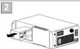
Illustration of a portable electronic device with control panel and indicator lights (no text or symbols visible)Pull the battery out, exposing the battery terminals and wires. Disconnect the wires from the terminals.
natural_image
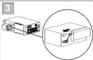
Diagram of a device with an inset close-up showing internal components (no text or symbols)Slide the new battery into the battery compartment. Connect the battery wires to the terminals as follows:
Black wire to Ground (-) terminal
Red wire to Positive (+) terminal
natural_image
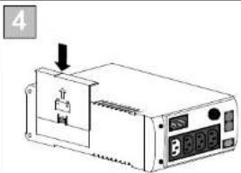
Diagram of a device with a labeled component and indicator lights (no readable text or symbols)Align the battery compartment cover with the grooves in the UPS. Slide the cover down until it locks.
Order Replacement Battery
The typical battery lifetime is 3-6 years (depending on the number of discharge cycles and operating temperature). A replacement battery can be ordered over the phone from APC, or the battery can be ordered on-line from the APC web site (http://www.apc.com, a valid credit card is required).
When ordering, please specify Battery Cartridge RBC2 (Back-UPS 350/500) or RBC17 (Back-UPS 650).
Transfer Voltage and Sensitivity Adjustment (optional)
In situations where the Back-UPS or connected equipment appears too sensitive to input voltage, it may be necessary to adjust the transfer voltage. This is a simple task requiring use of the front panel pushbutton. To adjust the transfer voltage, proceed as follows:
- Plug the Back-UPS into the utility power source. The Back-UPS will be in a Standby Mode (no indicators lit)
- Press the front panel pushbutton fully inward for 10 seconds. All indicators on the Back-UPS will flash to acknowledge going into Programming Mode.
- The Back-UPS will then indicate its current Sensitivity Setting, as shown in the following table.
| Indicators Flashing | Sensitivity Setting | Input Voltage Range (for utility operation) | Use When |
| 1(yellow) | Low 160 - 278 | Vac Input voltage is extremely low or high. Not recommended for computer loads. | |
| 2(yellow, and red) | Medium (factory default) | 180 - 266 Vac Back-UPS frequently goes On Battery. | |
| 3(yellow, red, and red) | High 196 - 256 | Vac Connected equipment is sensitive to voltage fluctuations (recommended). |
- To select the Low Sensitivity setting, press the pushbutton until the yellow indicator is flashing.
- To select the Medium Sensitivity setting, press the pushbutton until the yellow and red indicators (second and third from the topt are flashing.
- To select the High Sensitivity setting, press the pushbutton until yellow and both red indicators (bottom three) are flashing.
- To exit without changing the Sensitivity Setting, press the pushbutton until the green indicator is flashing.
- Once in Programming Mode, if the pushbutton is not pressed within 5 seconds, the Back-UPS will exit Programming Mode; all indicators will extinguish.
Troubleshooting
Use the tables below to solve minor Back-UPS installation and operation problems. Consult APC On-line Technical Support or call APC Technical Support for assistance with problems that cannot be resolved using this document:
| Possible Cause Procedure |
Back-UPS will not switch on
| Back-UPS not connected to an AC power source. | Check that the Back-UPS power plug is securely connected to the wall outlet. | 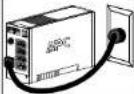 |
| Back-UPS circuit breaker "tripped". | Disconnect non-essential equipment from the Back-UPS. Reset the circuit breaker (located on the rear panel of the Back-UPS) by pushing the circuit breaker button fully inward until it catches. If the circuit breaker resets, switch the Back-UPS on and reconnect the equipment one-at-a-time. If the circuit breaker trips again, it is likely that one of the connected devices is causing the overload. | 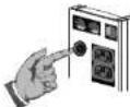 |
| Very low or no utility voltage. | Check the wall outlet that supplies power to the Back-UPS using a table lamp. If the lamp bulb is very dim, have the utility voltage checked by a qualified electrician. |  |
| Portable generator being used to provide input voltage. | Set the Transfer Voltage and Sensitivity setting to Low (see Transfer Voltage and Sensitivity Adjustment). By setting the Back-UPS to Low sensitivity, it can accept a wider range of input voltage. |
Back-UPS does not power computer/monitor/external drive during an outage
| Internal battery is not connected. | Check the battery connections |
| Computer, monitor or external disk/CD-ROM drive is plugged into a Surge Only outlet. | Move computer, monitor, or external drive power cord plug to the Battery Backup outlets. |
Back-UPS operates on battery although normal utility voltage exists
| Back-UPS circuit breaker "tripped". | Disconnect non-essential equipment from the Back-UPS. Reset the circuit breaker (located on the rear panel of the Back-UPS) by pushing the circuit breaker button fully inward until it catches. | 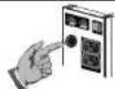 |
| The wall outlet that the Back-UPS is connected to does not supply utility power to the unit. | Connect the Back-UPS to another wall outlet or have a qualified electrician check the building wiring. | |
Back-UPS does not provide expected backup time
| Back-UPS is excessively loaded. | Unplug non-essential Battery Backup connected equipment, such as printers and plug them into Surge Only outlets.Note: Devices that have motors or dimmer switches (laser printers, heaters, fans, lamps, and vacuum cleaners, for example) should not be connected to the Battery Backup outlets. |
| Back-UPS battery is weak due to recent outage and has not had time to recharge. | Charge the battery. The battery charges whenever the Back-UPS is connected to a wall outlet. Typically, eight hours of charging time are needed to fully charge the battery from total discharge. Back-UPS run-time is reduced until the battery is fully charged. |
| Battery requires replacement. | Replace battery (see Order Replacement Battery). Balleries typically last 3-6 years, shorter if subjected to frequent power outages or elevated temperatures. |
A red indicator is lit
| Battery is not connected properly. | Check the battery connections. |
| The Overload indicator is lit if equipment connected to the Battery Backup outlets is drawing more power than the Back-UPS can provide. | Move one or more equipment power plugs to the Surge Only outlets. |
| Battery requires replacement. | The battery should be replaced within two weeks (see "Order Replacement Battery"). Failure to replace the battery will result in reduced run-time during a power outage. |
Red indicators are flashing
| Back-UPS failure. Call APC for service. |
Replace Battery indicator lit and an alarm sounds when the Back-UPS is turned on
| Internal battery not connected. Check the battery connections. |
Specifications
| Input Voltage (on line) | 180 - 266 Vac (default setting) |
| Frequency Limits (on line) | 47 - 63 Hz (auto-sensing) |
| On Battery Waveshape | Stepped Sine Wave |
| Maximum Load | 350 VA - 210 W 500 VA - 300 W 650 VA - 400 W |
| Typical Recharge Time | 8 Hours |
| Operating Temperature | 0^ to 40^ C( 32^ to104^ F) |
| Storage Temperature | - 15^ to 45^ C( 5^ to113^ F) |
| Operating and Storage Relative Humidity | 5 to 95% non-condensing |
| Size (H x W x D) | 16.5 x 9.2 x 28.5 cm (6.5 x 3.6 x 11.2 inches) |
| Weight | 350 VA - 5.7 kg (12.5 lb) 500 VA - 5.9 kg (12.9 lb) 650 VA - 6.2 kg (13.6 lb.) |
| Shipping Weight | 350 VA - 6.8 kg (14.9 lb) 500 VA - 7.0 kg (15.3 lb) 650 VA - 7.3 kg (16.1 lb.) |
| EMI Classification | EN 55022, IEC 801-2 and 801-4 (level IV), and IEC 801-3 (level III) |
| On Battery Run-Time | 350 VA - 13.2 minutes (typical) - computer and 17" (43.2 cm) monitor. 500 VA - 10.8 minutes (typical) - computer and 21" (53.3 cm) monitor. 650 VA - 17 minutes (typical) - computer and 21" (53.3 cm) monitor. |
Back-UPS Storage
Before storing, charge the Back-UPS for at least eight hours. Store the Back-UPS covered and upright in a conol. dry location. During storage, recharge the battery in accordance with the following table:
| Storage Temperature | Recharge Frequency | Charging Duration |
| -5° to 30°C (23° to 86°F) | Every 6 months | 8 hours |
| 30° to 45°C (86° to 113°F) | Every 3 months | 8 hours |
Please contact APC Technical Support to troubleshoot the unit before returning it to APC.
Service
Note: If the UPS requires service, do not return it to the dealer. The following steps should be taken:
- Consult the Troubleshooting section to eliminate common problems.
- Determine if the circuit breaker is tripped. If the circuit breaker is tripped, reset the breaker and determine if the problem still exists.
-
If the problem persists, consult the APC Worldwide Web site (www.apcc.com) or call customer service.
-
Record the model number of the UPS, the serial number, and the date purchased. Be prepared to troubleshoot the problem over the telephone with a technician. If this is not successful, the technician will issue a Return Merchandise Authorization Number (RMA#) and a shipping address.
-
If the UPS is under warranty, repairs are free. If not, there is a repair charge.
-
Pack the UPS in its original packaging. If the original packing is not available, ask customer service about obtaining a new set. Pack the UPS properly to avoid damage in transit.
Note: Never use Styrofoam ^TM beads for packaging. Damage sustained in transit is not covered under warranty (insuring the package for full value is recommended).
- Write the RMA# on the outside of the package.
- Return the UPS by insured, prepaid carrier to the address provided by customer service.
Warranty
The standard warranty is two (2) years from the date of purchase. APC's standard procedure is to replace the original unit with a factory reconditioned unit. Customers who must have the original unit back due to assigned asset tags and set depreciation schedules must declare such a need at first contact with an APC Technical Support representative. APC will ship the replacement unit once the defective unit has been received by the repair department, or cross ship upon the receipt of a valid credit card number. The customer pays for shipping the unit to APC. APC pays ground freight transportation costs to ship the replacement to the customer.
APC Contact Information
 | USA/Canada | 1.800.800.4272 |
| Mexico | 292.0253 / 292.0255 | |
| Brazil | 0800.12.72.1 | |
| Worldwide | 1.401.789.5735 | |
| Internet | http://www.apc.com | |
| Technical Support | http://www.apc.com/support |