
GPR378 - Fitnessudstyr Body-Solid - Gratis brugsanvisning og manual
Find enhedens vejledning gratis GPR378 Body-Solid i PDF-format.

Brugerspørgsmål om GPR378 Body-Solid
0 spørgsmål om dette apparat. Besvar dem du kender, eller stil dit eget.
Stil et nyt spørgsmål om dette apparat
Download vejledningen til din Fitnessudstyr i PDF-format gratis! Find din vejledning GPR378 - Body-Solid og tag din elektroniske enhed tilbage i hånden. På denne side er alle dokumenter nødvendige for brugen af din enhed offentliggjort. GPR378 af mærket Body-Solid.
BRUGSANVISNING GPR378 Body-Solid
GPR378
Body-Solid®
natural_image
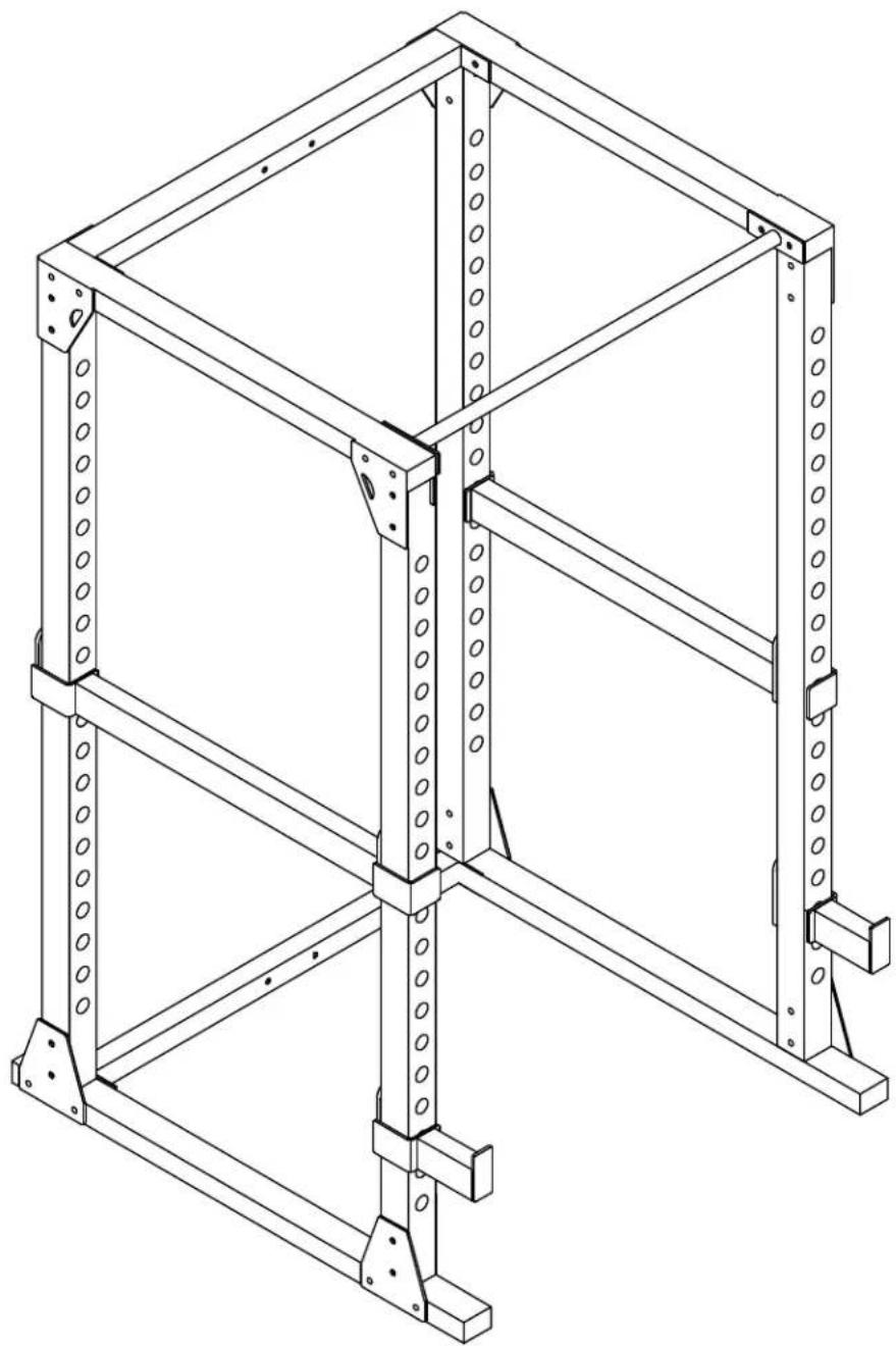
Technical line drawing of a multi-level metal shelving unit (no text or symbols)STEP
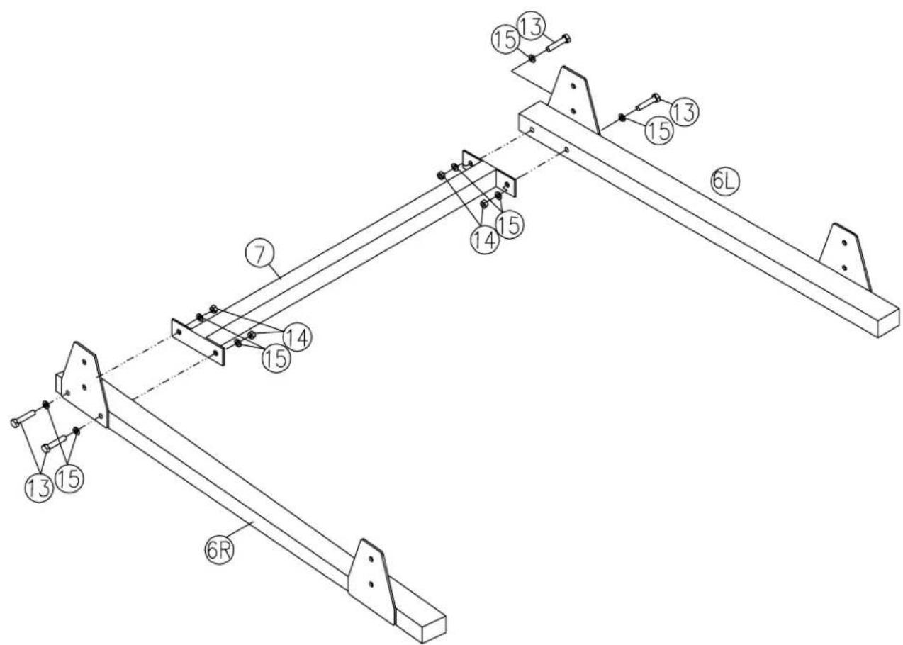
1
Be careful to assemble all components in the sequence they are presented.
NOTE:
Finger tighten all hardware in this step. Do Not wrench tighten until end of Step 5.
A. Attach the Right Side Bottom Frame (6R) to Rear Bottom Frame (7) by using:
Two 13 (1/2" x 4" hex head bolt)
Four 15 (1/2" washer)
Two 14 (1/2" nylon lock nut)
B. Attach the Left Side Bottom Frame (6L) to Rear Bottom Frame (7) by using:
Two 13 (1/2" x 4" hex head bolt)
Four 15 (1/2" washer)
Two 14 (1/2" nylon lock nut)

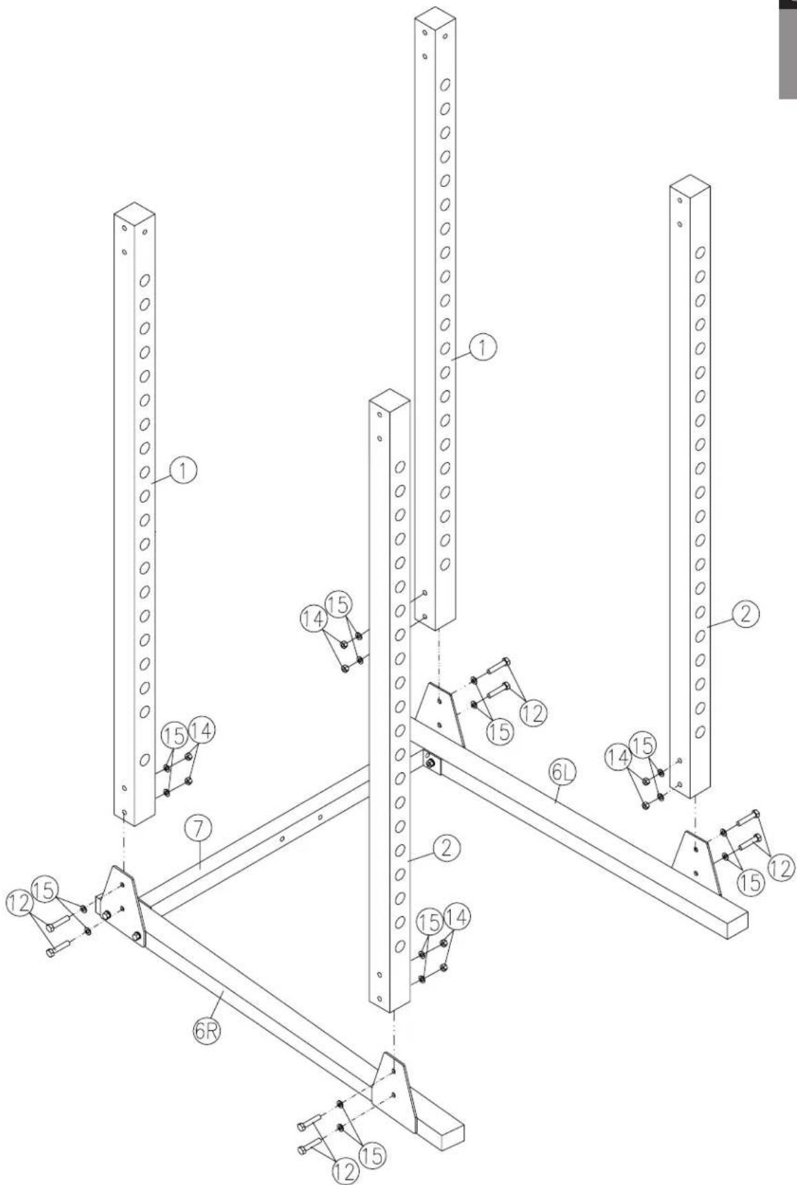
STEP
2
Be careful to assemble all components in the sequence they are presented.
NOTE:
Finger tighten all hardware in this step. Do Not wrench tighten until end of Step 5.
A. Connect Back Upright (1) and Front Upright (2) to Right Side Bottom Frame (6R) by using:
Four 12 (1/2" x 4" hex head bolt)
Eight 15 (1/2" washer)
Four 14 (1/2" nylon lock nut)
B. Connect Back Upright (1) and Front Upright (2) to Left Side Bottom Frame (6L) by using:
Four 12 (1/2" x 4" hex head bolt)
Eight 15 (1/2" washer)
Four 14 (1/2" nylon lock nut)
STEP
2
STEP
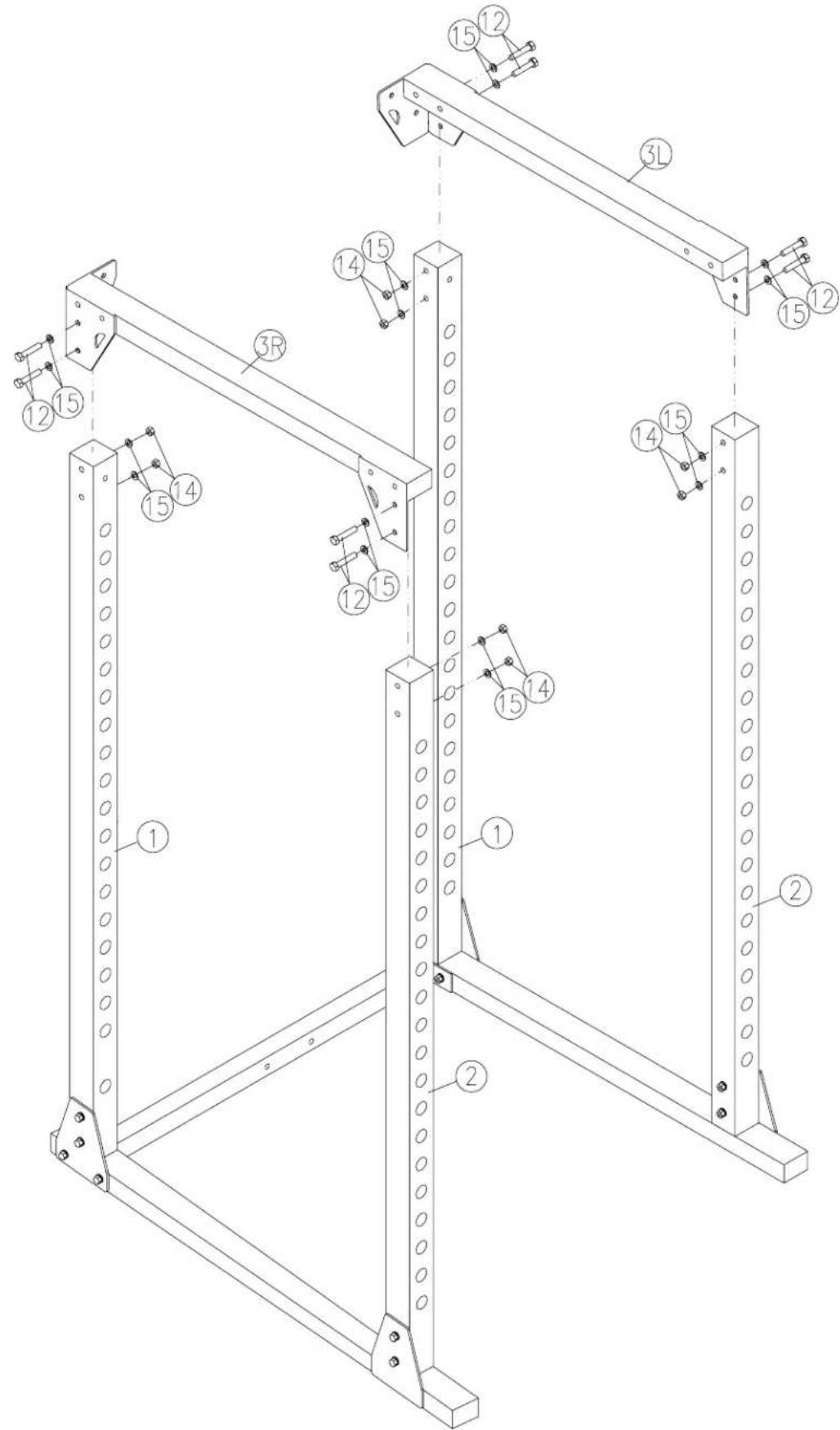
3
Be careful to assemble all components in the sequence they are presented.
NOTE:
Finger tighten all hardware in this step. Do Not wrench tighten until end of Step 5.
A. Attnach Left Side Top Frame (3L) to Back Upright (1) and Front Upright (2) by using:
Four 12 (1/2" x 4" hex head bolt)
Eight 15 (1/2" washer)
Four 14 (1/2" nylon lock nut)
B. Attach Right Side Top Frame (3R) to Back Upright (1) and Front Upright (2) by using:
Four 12 (1/2" x 4" hex head bolt)
Eight 15 (1/2" washer)
Four 14 (1/2" nylon lock nut)
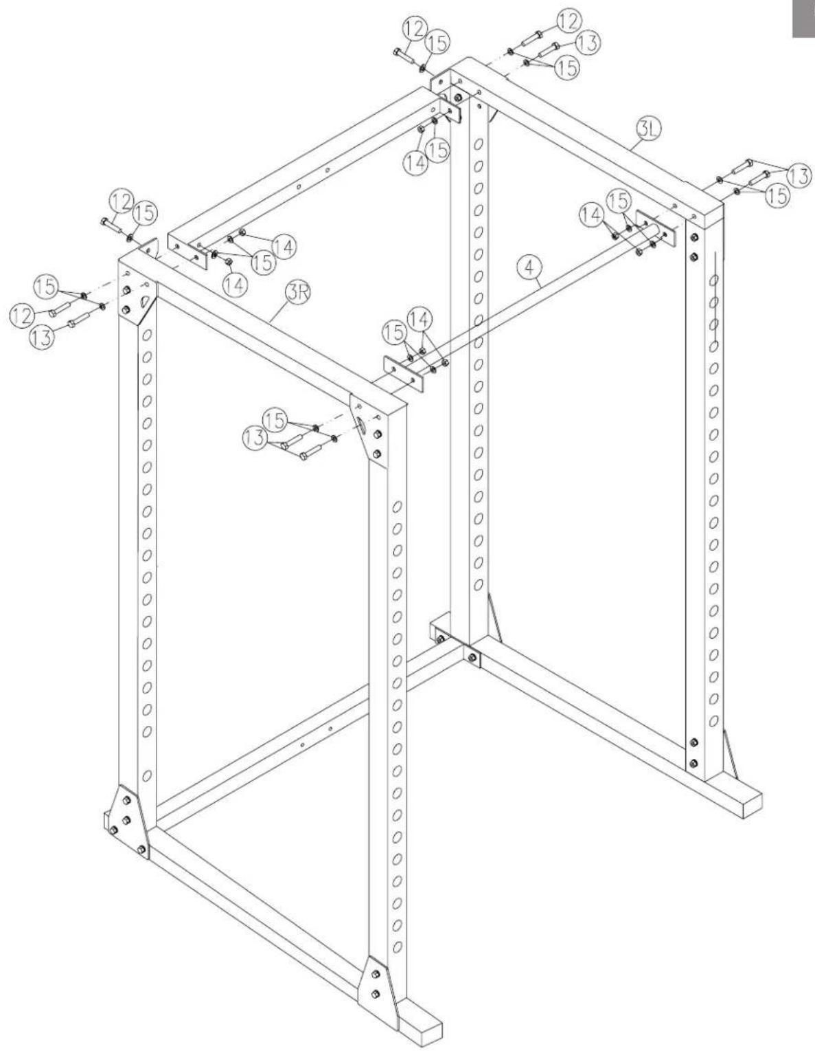
STEP
4
Be careful to assemble all components in the sequence they are presented.
NOTE:
Finger tighten all hardware in this step. Do Not wrench tighten until end of Step 5.
A. Connect Rear Top Frame (5) to Left Side Top Frame (3L) and Right Side Top Frame (3R) by using:
Six 12 (1/2" x 4" hex head bolt)
Ten 15 (1/2" washer)
Four 14 (1/2" nylon lock nut)
B. Connect Chin Up Bar (4) to Left Side Top Frame (3L) and Right Side Top Frame (3R) by using:
Four 13 (1/2" x 4 1/8" hex head bolt)
Eight 15 (1/2" washer)
Four 14 (1/2" nylon lock nut)


STEP
5
Be careful to assemble all components in the sequence they are presented.
NOTE:
Finger tighten all hardware in this step. Do Not wrench tighten until end of Step 5.
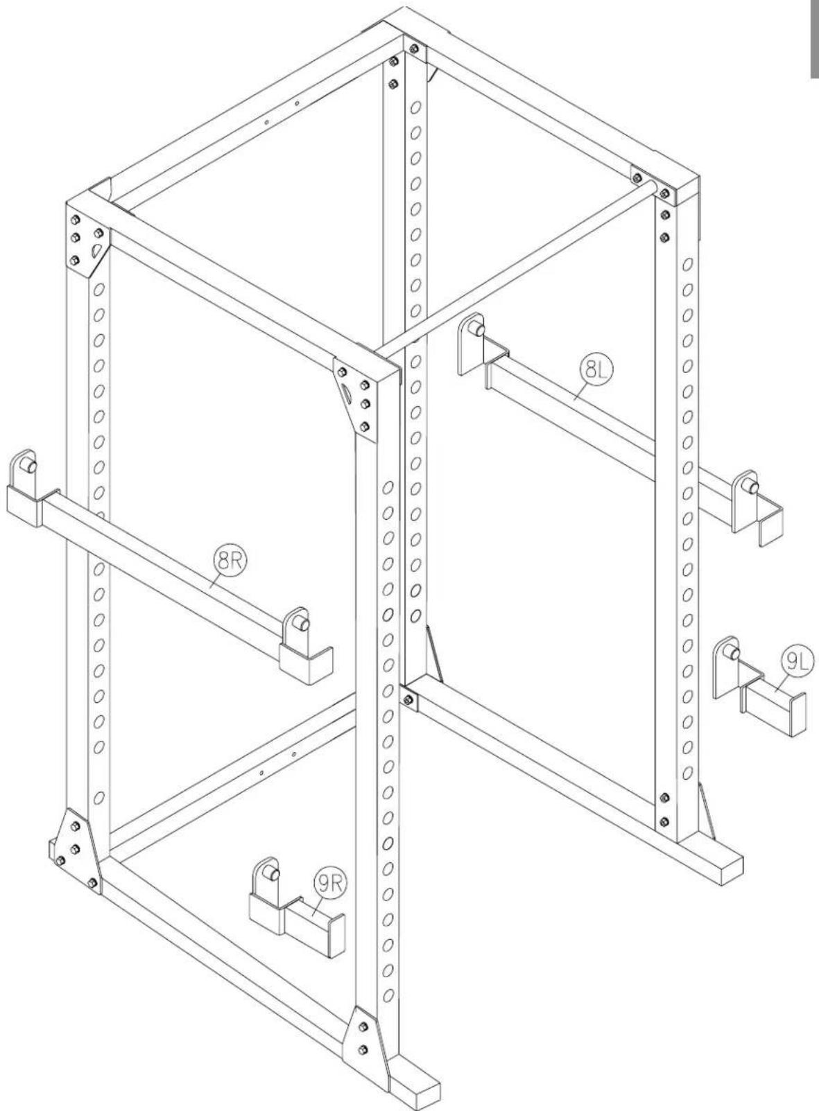
A. Connect Right Safety Catch (8R), Left Safety Catch (8L), Right Lift Off (9R), Left Lift Off (9L) to the desired positions.
B. Enjoy your workout!
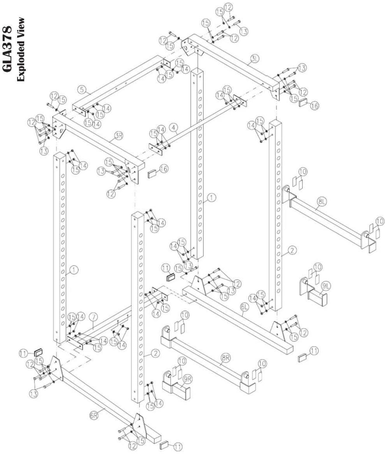
GLA378 Hardware
PART#
QTY
DESCRIPTION
1 2 BACK UPRIGHT
2 2 FRONT UPRIGHT
3 2 SIDE TOP FRAME
4 1 CHIN UP BAR
5 1 REAR TOP FRAME
6 1 SIDE BOTTOM FRAME
7 1 REAR BOTTOM FRAME
8 2 SAFETY CATCH
9 2 LIFT OFF
10 12 CUSHION
11 4 END CAP 3"×2"
12 20 HEX HEAD BOLT 1/2"×4" PARTIAL THREAD
13 10 HEX HEAD BOLT 1/2"×4 1/8" PART.THR.
14 30 1/2" NYLON LOCK NUT
15 60 1/2" WASHER
16 2 END CAP 3"×2"
1900 S. Des Plaines Ave.
Forest Park, Il 60130
1 (800) 556-3113
Hours: M-F 8:30 - 5:00
www.bodysolid.com
Mærke : Body-Solid
Model : GPR378
Kategori : Fitnessudstyr