KI7862FF0 - Køleskab NEFF - Gratis brugsanvisning og manual
Find enhedens vejledning gratis KI7862FF0 NEFF i PDF-format.


Pick your language and provide your email: we'll send you a specifically translated version.
Brugerspørgsmål om KI7862FF0 NEFF
0 spørgsmål om dette apparat. Besvar dem du kender, eller stil dit eget.
Stil et nyt spørgsmål om dette apparat
Ingen spørgsmål endnu. Vær den første til at stille et.
Download vejledningen til din Køleskab i PDF-format gratis! Find din vejledning KI7862FF0 - NEFF og tag din elektroniske enhed tilbage i hånden. På denne side er alle dokumenter nødvendige for brugen af din enhed offentliggjort. KI7862FF0 af mærket NEFF.
BRUGSANVISNING KI7862FF0 NEFF
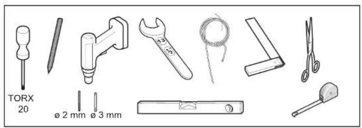
text_image
TORX 20 Ø 2 mm Ø 3 mm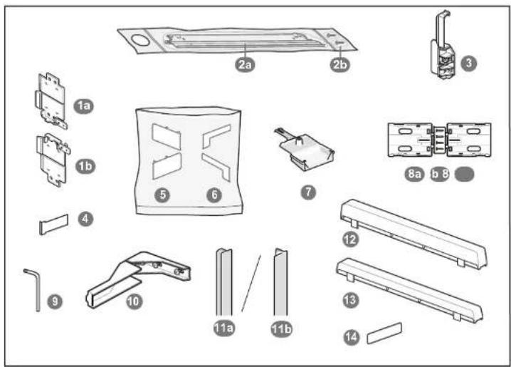
text_image
Exploded view diagram of a mechanical assembly with numbered parts for identification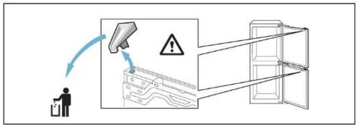
text_image
Diagram illustrating a safety warning with a person using a device and a warning sign, alongside a 3D diagram of an open refrigerator.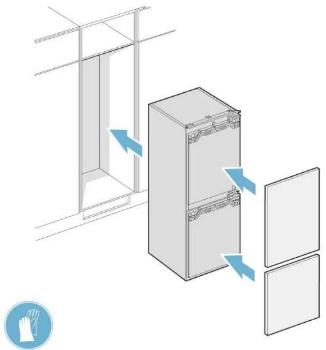
natural_image
Diagram of a refrigerator with doors and a door, showing airflow direction (no text or symbols)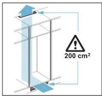
text_image
200 cm²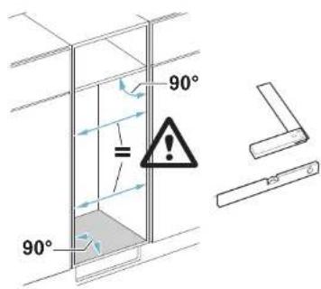
text_image
90° = 90°8001029860(9704)
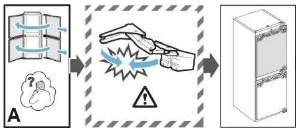
flowchart
graph LR
    A["Refrigeration with cooling"] --> B["Applification of explosion"]
    B --> C["Warning: exclamation mark"]
    C --> D["Fire inside refrigerator"]
text_image
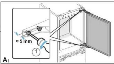
≈ 5 mm A₁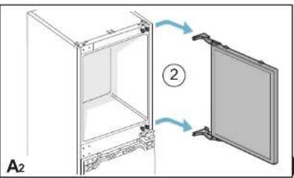
natural_image
Diagram of a refrigerator interior with two doors open, showing structural changes (no text or symbols)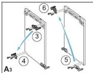
text_image
A3 ③ ④ ⑤ ⑥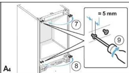
text_image
A₄ 7 ≈ 5 mm 8 9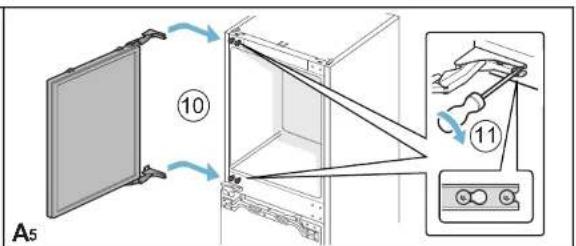
text_image
A5 ⑩ ⑪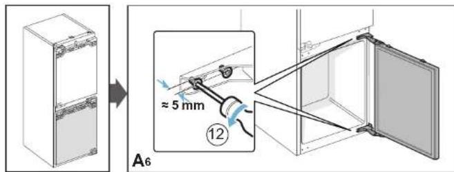
text_image
A6 ≈ 5 mm ⑫ 12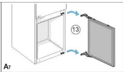
text_image
A7 ⑬ ⑬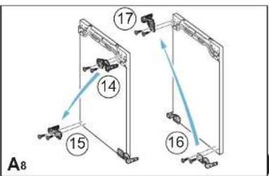
flowchart
graph TD
    A["Component 15"] --> B["Component 14"]
    B --> C["Component 17"]
    C --> D["Component 16"]
    D --> E["Component 15"]
    style A fill:#f9f,stroke:#333
    style B fill:#ccf,stroke:#333
    style C fill:#cfc,stroke:#333
    style D fill:#fcc,stroke:#333
    style E fill:#ffc,stroke:#333
text_image
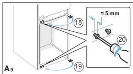
A9 18 19 ≈ 5 mm 20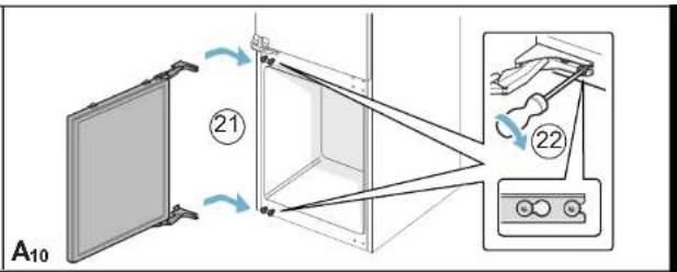
text_image
A10 ②1 ②2
flowchart
graph TD
    A["Storage Room B"] --> B["1a Refrigerator"]
    B --> C["1b Refrigerator"]
    C --> D["16 mm Refrigerator"]
    D --> E["2 Refrigerator"]
    E --> F["3 Refrigerator"]
    F --> G["1a Refrigerator"]
    F --> H["1b Refrigerator"]
    G --> I["1a Refrigerator"]
    H --> J["1b Refrigerator"]
    style A fill:#f9f,stroke:#333
    style B fill:#ccf,stroke:#333
    style C fill:#ccf,stroke:#333
    style D fill:#cfc,stroke:#333
    style E fill:#fcc,stroke:#333
    style F fill:#fcc,stroke:#333
    style G fill:#fcc,stroke:#333
    style H fill:#fcc,stroke:#333

text_image
B3 ⑤ 2a ⑥ click ⑦
text_image
B4 4 mm ⑧ ⑨ ⑩
flowchart
graph LR
    A["Component 4"] --> B["B5"]
    B --> C["Component 11"]
    C --> D["Component 5"]
    D --> E["B6"]
    E --> F["Component 12"]
    E --> G["Component 13"]
    E --> H["Component 14"]
    E --> I["Component 15"]

flowchart
graph TD
    A["16"] --> B["B7"]
    B --> C["17"]
    C --> D["7"]
    D --> E["B8"]
    E --> F["18"]
    F --> G["B9"]
    style A fill:#f9f,stroke:#333
    style B fill:#ccf,stroke:#333
    style C fill:#cfc,stroke:#333
    style D fill:#fcc,stroke:#333
    style E fill:#cff,stroke:#333
    style F fill:#ffc,stroke:#333
    style G fill:#fcc,stroke:#333

text_image
41 mm B10 20 21 22 23 24 25 26 click B11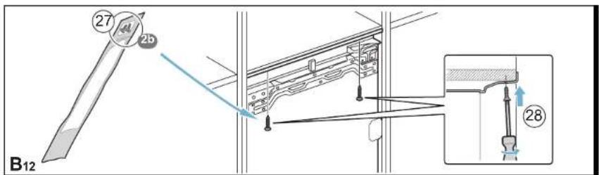
text_image
27 2b B12 28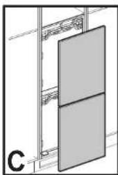
natural_image
Diagram of a cabinet or rack with two panels, no visible text or symbols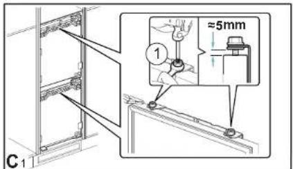
text_image
C1 ① ≈5mm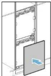
natural_image
Diagram of a server rack with a highlighted panel showing a blue arrow (no text or symbols present)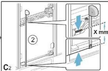
text_image
② C2 X mm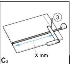
text_image
C₃ X mm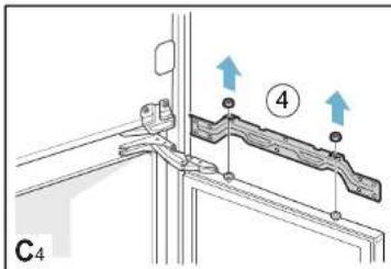
text_image
C4 ④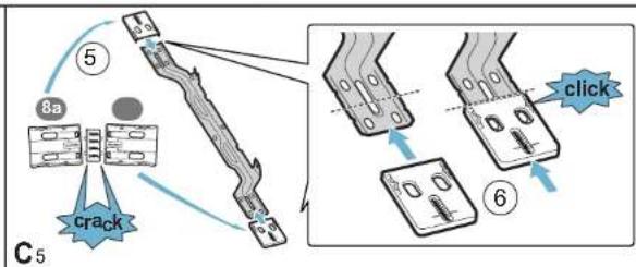
flowchart
graph TD
    A["Crack"] --> B["Step 5: Crack"]
    B --> C["Step 6: Click"]
    C --> D["Step 7: Click"]
    D --> E["Step 8a: Crack"]
    style A fill:#f9f,stroke:#333
    style B fill:#ccf,stroke:#333
    style C fill:#cfc,stroke:#333
    style D fill:#fcc,stroke:#333
    style E fill:#ffc,stroke:#333
text_image
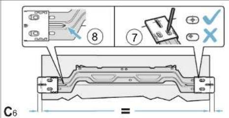
C6 8 7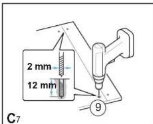
text_image
2 mm 12 mm C7 9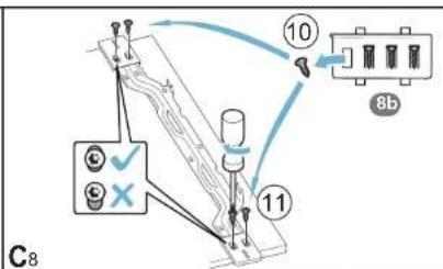
text_image
C8 10 8b 11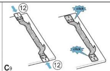
text_image
12 12 C9 click click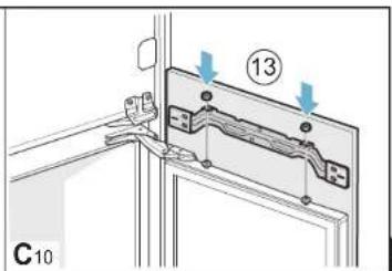
text_image
⑬ C10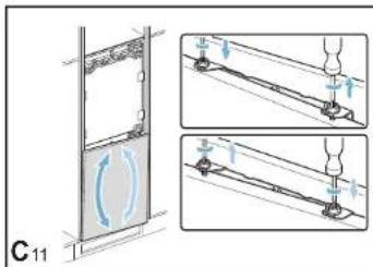
text_image
C11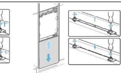
text_image
Technical diagram showing mechanical assembly steps with labeled components and directional arrows indicating motion or movement.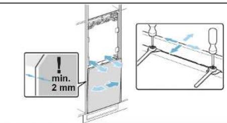
text_image
min. 2 mm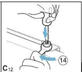
text_image
C12 14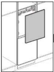
natural_image
Pure architectural line drawing of a cabinet or wardrobe unit with no text, numbers, or symbols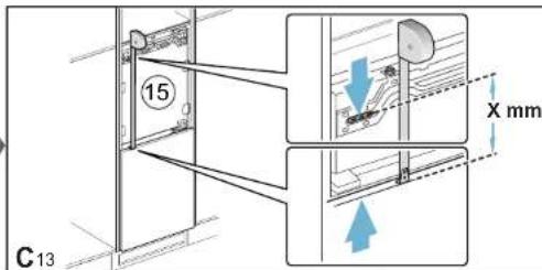
text_image
15 C13 X mm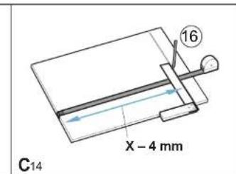
text_image
C14 X - 4 mm 16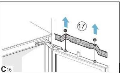
text_image
C15 17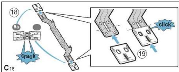
flowchart
graph TD
    A["Crack"] --> B["8a"]
    B --> C["Initial State"]
    C --> D["Click"]
    D --> E["Final State"]
    style A fill:#f9f,stroke:#333
    style B fill:#ccf,stroke:#333
    style C fill:#cfc,stroke:#333
    style D fill:#fcc,stroke:#333
    style E fill:#cff,stroke:#333
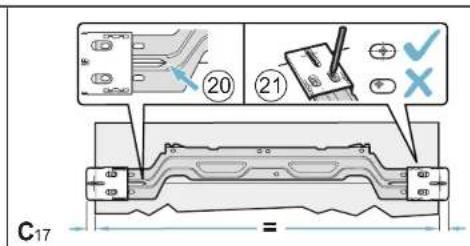
text_image
C17 = 20 21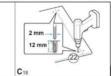
text_image
2 mm 12 mm C18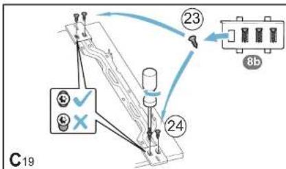
text_image
C19 23 24 8b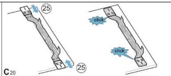
text_image
C 20 25 25 click click click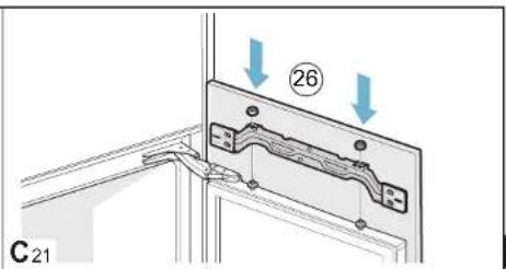
text_image
26 C21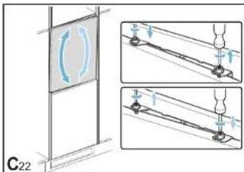
text_image
C22
text_image
Technical diagram showing mechanical assembly with directional arrows and component placement, likely illustrating a rail or mounting mechanism.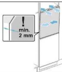
text_image
min. 2 mm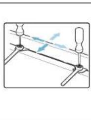
natural_image
Pure mechanical diagram showing a lever system with pivot points and motion lines (no text or symbols)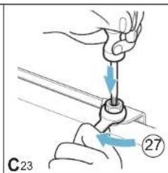
text_image
C23 27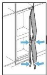
natural_image
Diagram showing a mechanical or structural component with directional arrows indicating movement or force (no text or symbols present)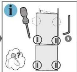
text_image
Diagram illustrating a mechanical or electrical component with labeled parts and an unknown symbol, likely from an electronics or safety instruction.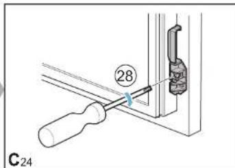
text_image
C-24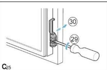
text_image
③0 ②9 C25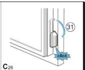
text_image
③1 click C26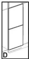
text_image
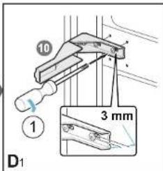
10 ① 3 mm D₁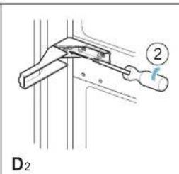
text_image
D₂ ②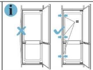
text_image
Diagram showing two door frame arrangements with directional arrows and a question mark, likely illustrating a basic electrical or mechanical system concept.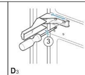
text_image
D₃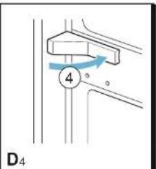
text_image
D₄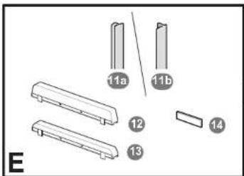
text_image
11a 11b 12 13 14 E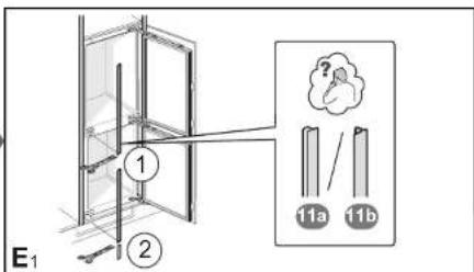
text_image
E₁ ① ② 11a 11b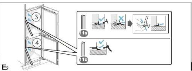
text_image
E2 ③ ④ 11a 11b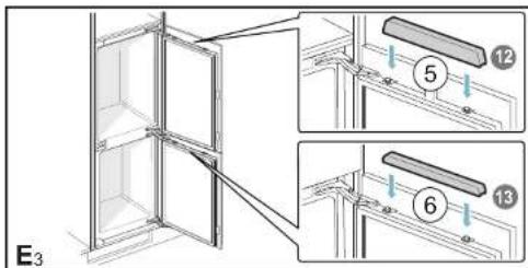
text_image
E₃ ⑤ ⑥ ⑬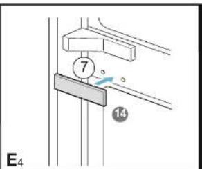
text_image
7 14 E₄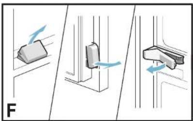
natural_image
Three-panel diagram showing mechanical components with directional arrows, no text or symbols present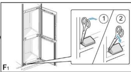
text_image
F₁ ① ②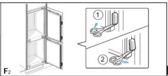
text_image
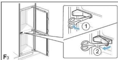
F₂ ① ②