TNL053 - Komfur Summit - Gratis brugsanvisning og manual
Find enhedens vejledning gratis TNL053 Summit i PDF-format.


Brugerspørgsmål om TNL053 Summit
0 spørgsmål om dette apparat. Besvar dem du kender, eller stil dit eget.
Stil et nyt spørgsmål om dette apparat
Download vejledningen til din Komfur i PDF-format gratis! Find din vejledning TNL053 - Summit og tag din elektroniske enhed tilbage i hånden. På denne side er alle dokumenter nødvendige for brugen af din enhed offentliggjort. TNL053 af mærket Summit.
BRUGSANVISNING TNL053 Summit
INSTALLATION INSTRUCTIONS BUILT-IN GAS AND ELECTRIC SURFACE UNITS (Cooktops)
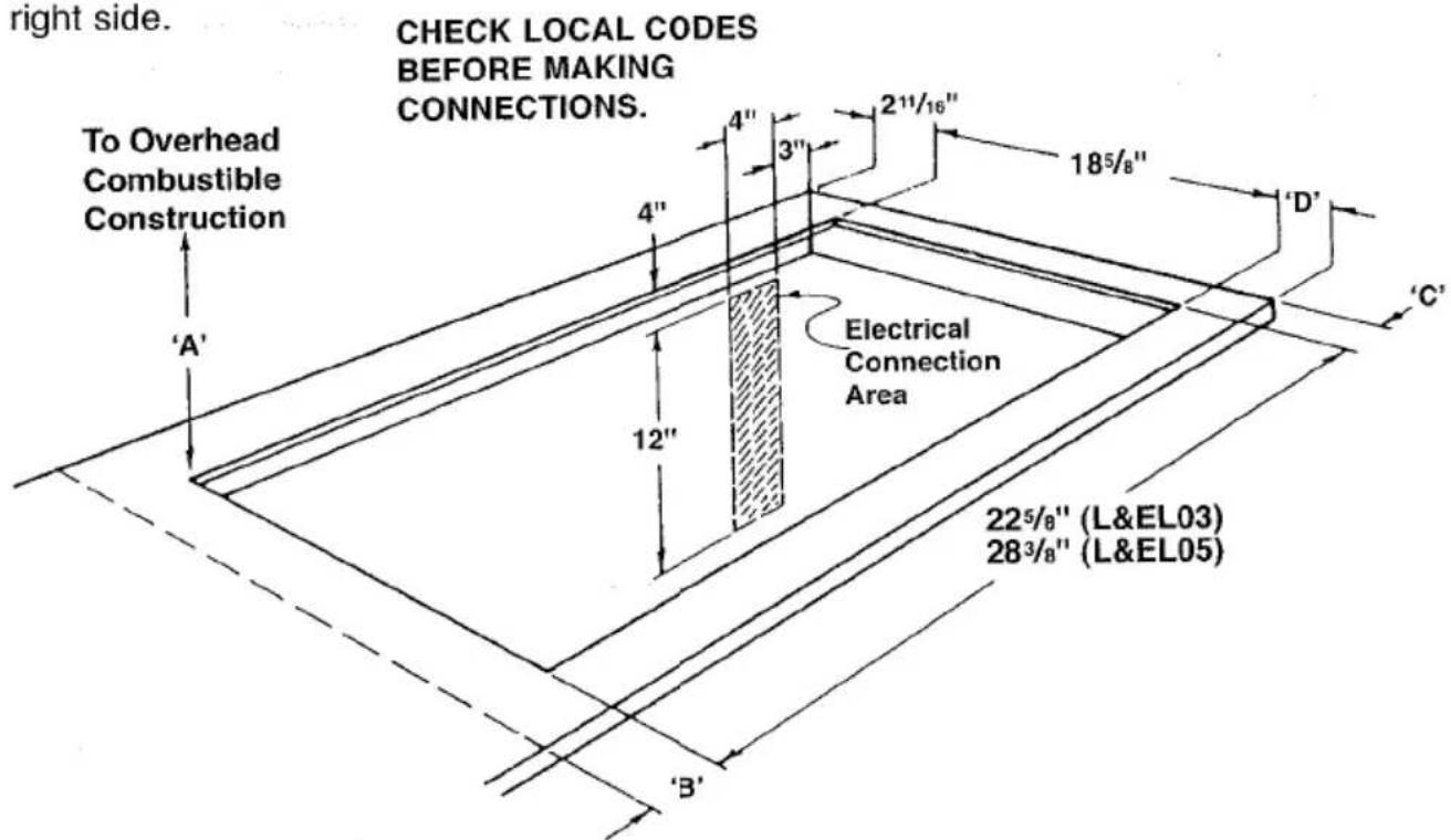
CABINET OPENING
Prepare the cabinet accurately so your unit will fit properly. Below are cabinet cutout dimensions. The dimensions are for the unit to be mounted so the knobs are on the right side. CHECK LOCAL CODES
text_image
right side. CHECK LOCAL CODES BEFORE MAKING CONNECTIONS. To Overhead Combustible Construction 4" 3" 2"1/16" 185/8" A' 12" Electrical Connection Area 225/8" (L&EL03) 283/8" (L&EL05) 'B'"A" 30" See CABINET PREPARATIONS Section.
"B" 2 ^11/16 " To Adjacent Vertical Combustible Surface.
"C" 1" To Adjacent Vertical Combustible Surface.
"D" 2 5/8" Minimum.
CAUTION:
To eliminate the hazard of reaching over the heated surface units, cabinet storage space located above the surface units should be avoided. If cabinet storage is to be provided, the hazard can be reduced by installing a range hood that projects horizontally a minimum of 5 inches beyond the bottom of the cabinets.
INSTALLATION
It is the responsibility of your installer to make certain that your range is properly installed. Situations caused by improper installation are not covered under the warranty. Any expenses incurred due to such situations will not be paid by the manufacturer of the appliance.
IMPORTANT – Read and save these instructions. Save for local electrical inspector's use.
GAS SURFACE UNITS
MOUNTING THE BUILT-IN TOP UNIT
Place unit in cabinet opening with the valves on the right side. Raise the top by removing top burner valve knobs, and lifting upward on the front edge of the main top. Secure unit to top of cabinets with four No. 8 screws through holes provided in the top flanges of the burner box.
The gas pressure regulator supplied must be used with this unit. If it is necessary to convert this unit from use with natural gas to L.P., or L.P. to natural, see "To Convert and/or Adjust" in "Alignments and Adjustments" section. The installation must conform with local codes. In the absence of local codes, the National Fuel Gas Code Z223.1 latest edition.
A MANUAL GAS VALVE MUST BE INSTALLED IN AN ACCESSIBLE LOCATION IN THE GAS LINE EXTERNAL TO THE UNIT FOR THE PURPOSE OF TURNING ON OR SHUTTING OFF GAS TO THE UNIT.
WARNING
ELECTRICAL GROUNDING INSTRUCTIONS
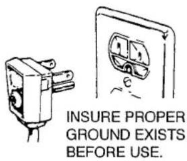
This appliance is equipped with a three prong grounding plug for your protection against shock hazard and should be plugged directly into a properly grounded receptacle. Do not cut or remove the grounding prong from this plug.
text_image
INSURE PROPER GROUND EXISTS BEFORE USE.Flexible Connectors - If the gas range/oven is connected to a gas supply with a metal flexible connector, move the range/oven with CAUTION for service or cleaning. Flexible connectors are not intended for repeated bending. Do not allow cleaners to make contact with flexible connectors.
The connector and its fittings are designed for use only on the original installation and are not to be reused for another appliance or at another location. Connectors must comply with ANSI Z21.24.
BUILT-IN TOP UNITS WITH NO POWER CORD
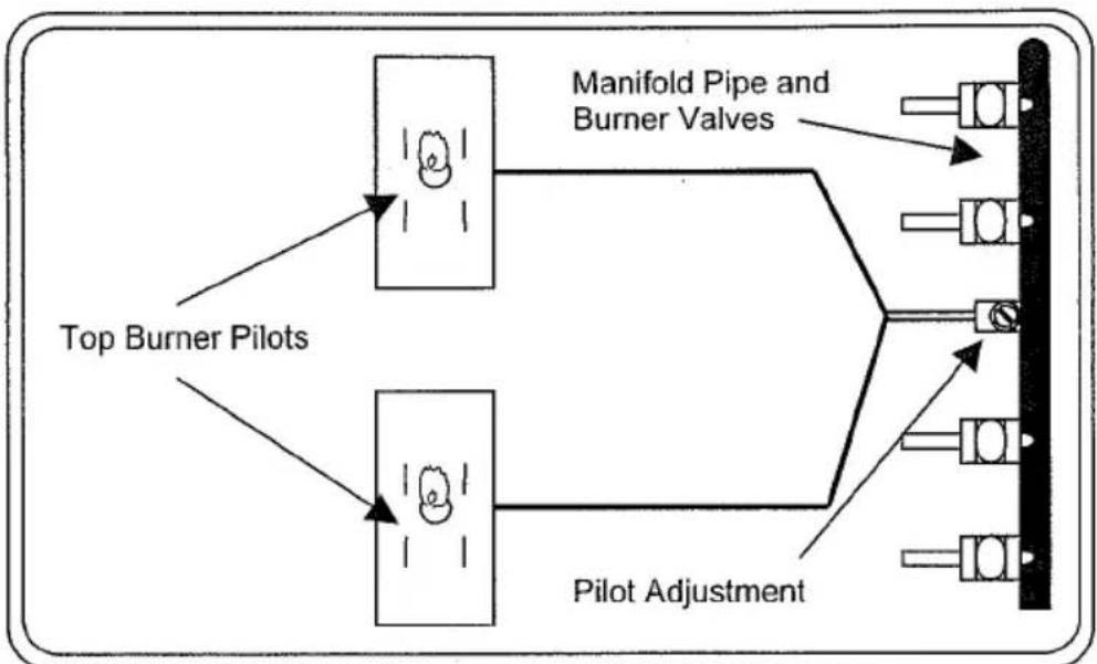
If your built-in top unit is not equipped with a power cord, the unit operates by standing pilot lights or a 9 volt battery powered ignition system. These units must be set up and maintained as outlined below.
Adjust the size of the top pilot flame until there is only a slight tip of yellow on the flame as described in the ALIGNMENTS AND ADJUSTMENTS section of the user manual. The adjustment screw is located on the side of the manifold pipe.
flowchart
graph TD
    A["Top Burner Pilots"] --> B["Manifold Pipe and Burner Valves"]
    C["Pilot Adjustment"] --> D["Manifold Pipe and Burner Valves"]
    B --> E["Output"]
    D --> F["Output"]
Built-In Top Unit with Pilots (Main Burners Not Shown)
On units with battery powered ignition, there are no top burner pilots. There are top ignitor electrodes in the same location as the top burner pilots. This ignition system requires one (1) 9 volt alkaline battery for operation. The battery is housed in an enclosure underneath the switch panel cover. It is recommended that you check and/or replace the battery at least once per year.
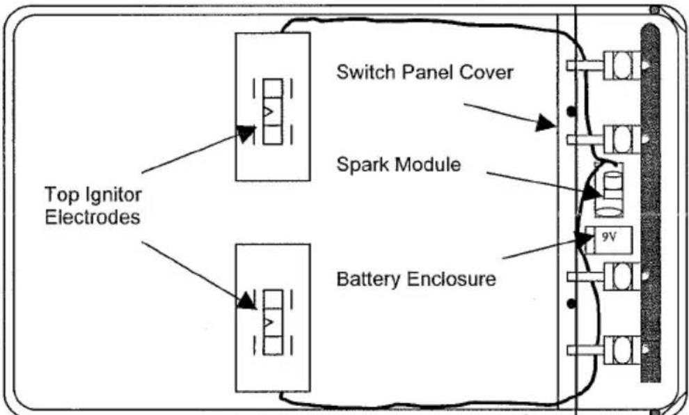
flowchart
graph TD
    A["Top Ignitor Electrodes"] --> B["Switch Panel Cover"]
    A --> C["Battery Enclosure"]
    B --> D["Spark Module"]
    C --> E["9V"]
Built-In Top Unit with Battery Ignition (Main Burners Not Shown)
Access the battery for periodic servicing as follows:
- Remove the burner grates and top burner knobs from the unit.
- Raise the main top by lifting it by the front edge.
• Use a hex driver to remove four (4) screws from the switch panel cover.
• Gently lay the switch panel cover over to the left.
• Use a hex driver to remove one (1) screw from the battery enclosure. - Check and/or replace the battery as recommended.
• Reinstall the battery enclosure.
• Reinstall the switch panel cover.
• Lower the main top and replace the grates and knobs.
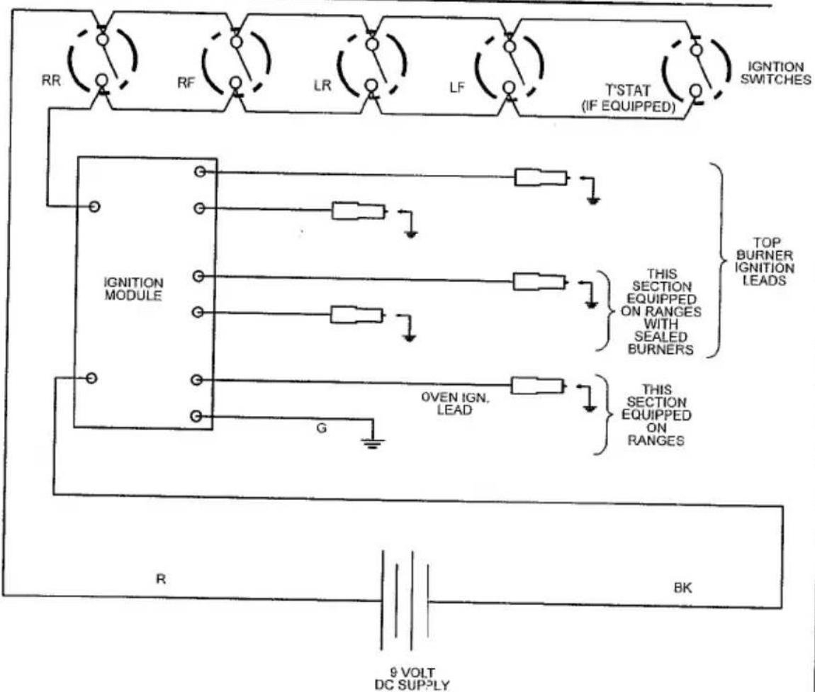
WIRING DIAGRAM FOR GAS RANGES AND SURFACE UNITS WITH BATTERY EQUIPMENT
text_image
RR RF LR LF T'STAT (IF EQUIPPED) IGNITION SWITCHES IGNITION MODULE G OVEN IGN. LEAD THIS SECTION EQUIPPED ON RANGES WITH SEALED BURNERS TOP BURNER IGNITION LEADS THIS SECTION EQUIPPED ON RANGES R BK 9 VOLT DC SUPPLYREFER ONLY TO FEATURES WHICH ARE EQUIPPED ON YOUR RANGE
180-6C162
TOP BURNER VALVES
Built-in top burner valves are operated by pressing the knob and turning it 90 degrees counter-clockwise to the "LITE" position. This position is also the "HI" position where maximum gas flow is obtained. Hold the knob in this position until the burner successfully lights.
If the burner fails to light within 10 seconds, turn the knob back to the "OFF" position. Let the unit sit at least 5 minutes to allow unburned gas to dissipate before attempting to light the burner again. If the problem persists, refer to the troubleshooting guide in your instruction manual or contact a service technician.
Once the burner has successfully lit, turn the knob to adjust the flame size as needed for the amount of food being cooked, or the size of the utensil.
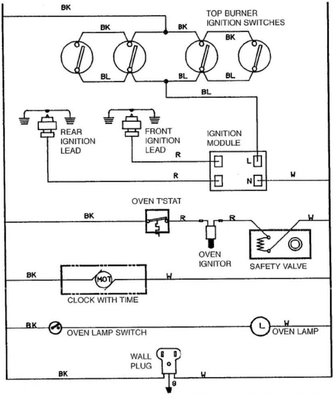
WIRING DIAGRAM FOR GAS SURFACE UNITS AND WALL OVENES
text_image
TOP BURNER IGNITION SWITCHES BK BK BL BL BL BL REAR IGNITION LEAD FRONT IGNITION LEAD IGNITION MODULE R L N W OVEN T'STAT BK R R W OVEN IGNITOR SAFETY VALVE BK MOT CLOCK WITH TIME Bk OVEN LAMP SWITCH L W OVEN LAMP BK WALL PLUG θREFER ONLY TO FEATURES WHICH ARE EQUIPPED ON YOUR RANGE WARNING-ELECTRICAL GROUNDING INSTRUCTIONS:
THIS APPLIANCE IS EQUIPPED WITH A THREE-PRONG GROUNDING PLUG FOR YOUR PROTECTION AGAINST SHOCK HAZARD AND SHOULD BE PLUGGED DIRECTLY INTO A PROPERLY GROUNDED THREE-PRONG RECEPTACLE. DO NOT CUT OR REMOVE THE GROUNDING PRONG FROM THE PLUG.
180-6C89 REV. 1
ELECTRIC SURFACE UNITS
MOUNTING THE BUILT-IN TOP UNIT
Place unit in cabinet opening with the knobs, on the right side. Raise the top by lifting upward on the front edge of the main top. Secure unit to top of cabinets with four No. 8 screws through holes provided in the top flanges of the burner box. Make electrical connection. Electrical connection should conform to local requirements and codes.
POWER CONNECTIONS TO APPLIANCES
We suggest that you have the dealer where you purchased your new range install it or have him arrange installation by a qualified electrician. Installation must conform with local codes. In addition, installation must conform with the National Electric Code NFPA70 latest edition.
WARNING—Be sure electric power is OFF at the fuse (breaker) box until the unit is installed and ready to operate. See appliance rating plate for maximum K.W. and amperage rating.
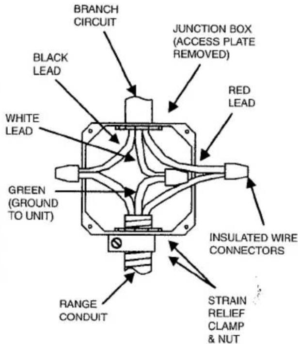
THREE-WIRE CONDUIT CONNECTION
text_image
BRANCH CIRCUIT JUNCTION BOX (ACCESS PLATE REMOVED) BLACK LEAD RED LEAD WHITE LEAD INSULATED WIRE CONNECTORS GREEN (GROUND TO UNIT) RANGE CONDUIT STRAIN RELIEF CLAMP & NUT240 VAC
- Remove the access plate to gain access to the electrical junction box.
- Install the three-wire range conduit and an appropriate strain relief clamp through the hole in the junction box.
- Use an appropriate insulated wire connector to connect the red and black wires from the range conduit to the corresponding red and black leads from the branch circuit.
- Connect the green (ground) wire from the range conduit to the white (neutral) lead from the branch circuit in like manner.
- Secure the strain relief clamp around the conduit and tighten the nut against the wall of the junction box.
- Tuck all wire leads into the junction box and replace the access plate removed earlier in step 1.
If local codes do not allow grounding through the neutral, refer to the illustration below of FOUR-WIRE CONDUIT CONNECTION.
FOUR-WIRE CONDUIT CONNECTION
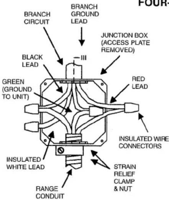
text_image
FOUR- BRANCH CIRCUIT BRANCH GROUND LEAD JUNCTION BOX (ACCESS PLATE REMOVED) BLACK LEAD III RED LEAD INSULATED WIRE CONNECTORS GREEN (GROUND TO UNIT) INSULATED WHITE LEAD STRAIN RELIEF CLAMP & NUT RANGE CONDUIT240 VAC
Effective January 1, 1996 the National Electrical Code requires that new construction (not existing) utilize a 4-conductor connection to an electric range.
- Remove the access plate to gain access to the electrical junction box.
- Install the three-wire range conduit and an appropriate strain relief clamp through the hole in the junction box.
- Use an appropriate insulated wire connector to connect the red and black wires from the range conduit to the corresponding red and black leads from the branch circuit.
- Connect the green (ground) wire from the range conduit to the grounding lead from the branch circuit in like manner.
- The white (neutral) lead from the branch circuit must be properly insulated away from all other leads.
- Secure the strain relief clamp around the conduit and tighten the nut against the wall of the junction box.
- Tuck all wire leads into the junction box and replace the access plate removed earlier in step 1.
NOTE: A 4-conductor connection is to be used when the appliance is installed in a mobile home or when local codes do not permit grounding through the neutral.