CRM 203-RF - Mikrofon Clockaudio - Gratis brugsanvisning og manual
Find enhedens vejledning gratis CRM 203-RF Clockaudio i PDF-format.


Brugerspørgsmål om CRM 203-RF Clockaudio
0 spørgsmål om dette apparat. Besvar dem du kender, eller stil dit eget.
Stil et nyt spørgsmål om dette apparat
Download vejledningen til din Mikrofon i PDF-format gratis! Find din vejledning CRM 203-RF - Clockaudio og tag din elektroniske enhed tilbage i hånden. På denne side er alle dokumenter nødvendige for brugen af din enhed offentliggjort. CRM 203-RF af mærket Clockaudio.
BRUGSANVISNING CRM 203-RF Clockaudio
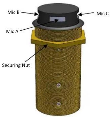
The CRM 203-RF is a tri-element boundary layer through table cardioid condenser microphone, with a built-in mechanism that will allows users to retract the microphone fully into the table. Engineered in high quality brass with built in shock mount and RF Iter. Available in black Nextel (CRM 203-RF) or san nickel (CRM 203N-RF).
text_image
Mic B Mic A Securing Nut Mic C- Oering 3 independently wired mics a + b + c .
- Fied with a magnec reed switch designed to prevent unwanted feedback from retracted microphones on power up. The switch contact is closed (ON) when the microphones are in the raised posion and open (OFF) when retracted. This is not designed to be used for privacy mung.
- Easy to Install.
- Low prole at surface level
- Unique ability to lock capsules away from sight when not in use
- Robust brass construcon
- Cardioid polar paern
• Built in RF Iter
• Balanced output - Supplied with 3 x 2m (6.6) 2 core + screen audio cable and 1 x grey 2 core cable for internal reed switch
• San Nickel (CRM 203N-RF) or Black Nextel (CRM 203-RF)
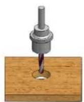
Fig A
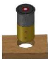
Fig B
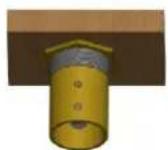
Fig C
Installaon guide
1) Drill a 58mm (2.25") hole through the table (Fig A).
2) Remove the nut and t the CRM 203-RF microphone through the 58mm (2.25") hole see (Fig B).
3) Replace nut and ghten to the underside of the table (Fig C).
4) Microphone conncons: mic A white cable in line with screws, mic B (90 deg from mic A) black cable and mic C (90 deg from mic A) black cable with red tag. For the three mics, Red Phase +, White Phase - and screen Ground.
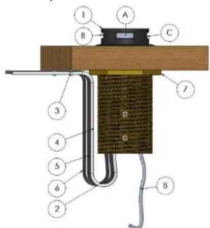
5) Using p-clamps provided x cables to the underside of the table ensuring there is sucient slack in the cable loom for the mic to operate (Fig D).
Grey 2 core (red and blue wires) is to be used for remote switching, screen is not used. Also note switch is open circuit when the mic is down. Please take note programming will be needed on the DSP side to allow the microphone to be muted once retracted.
text_image
I A B C 7 3 4 5 6 2 8Fig D, key:
1) Head in raised posion.
2) Loop cable allowing at least 25mm (1") out of the boom of the CRM.
3) Fit supplied P-clamp using self-tap screws.
4) White audio cable mic A.
5) Black audio cable mic B.
6) Black with red tag audio cable mic C.
7) Securing Nut.
8) Grey switch cable red and blue cores.