Knitmaster 326 - Symaskine Empisal - Gratis brugsanvisning og manual
Find enhedens vejledning gratis Knitmaster 326 Empisal i PDF-format.


Brugerspørgsmål om Knitmaster 326 Empisal
0 spørgsmål om dette apparat. Besvar dem du kender, eller stil dit eget.
Stil et nyt spørgsmål om dette apparat
Download vejledningen til din Symaskine i PDF-format gratis! Find din vejledning Knitmaster 326 - Empisal og tag din elektroniske enhed tilbage i hånden. På denne side er alle dokumenter nødvendige for brugen af din enhed offentliggjort. Knitmaster 326 af mærket Empisal.
BRUGSANVISNING Knitmaster 326 Empisal
KNITTER
INSTRUCTION MANUAL
natural_image
Black-and-white illustration of a woman with shoulder-length hair and bangs, waving her hand (no text or symbols)Empisal-Knitmaster®
MODEL-326
ENGLISH
ENJOY KNITTING WITH YOUR NEW
Empirical-Knitmaster®
326 PUNCH CARD KNITTER
text_image
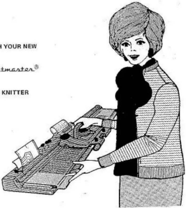
I YOUR NEW master® KNITTERCongratulations on the purchase of our new EMPISAL-KNITMASTER 326 Knitter.
You must often have wished you could dress yourself and your family in knitwear that you really like.
Follow the instructions and illustrations carefully and in no time at all you will be machine knitting – not only knitting, but also ENJOYING using your new knitting machine.
This little book has been revised many times, but if you have new suggestions which could help you and many others, write in — further ideas for alterations to improve it and make it easier to follow are always welcome.
You will have fun learning to knit and this booklet will help you. Should anything go wrong, PLEASE DO NOT WORRY – read the instructions again and soon you will be knitting with confidence and enthusiasm.
REMEMBER - ONLY PRACTICE MAKES PERFECT.
Your
Knitting Companion
UNPACKING THE MACHINE

natural_image
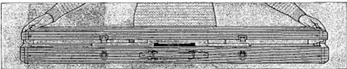
Illustration of two hands operating a wooden cylindrical device with four buttons (no text or symbols visible)- Place the machine on a flat table with the brandname on top and the handle away from you.
- Unlock both latches on the back of the machine.
natural_image
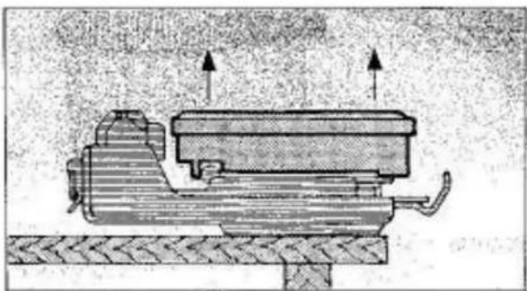
Technical line drawing of a wooden toolbox with hands adjusting its side (no text or symbols)- Lift machine lid slightly, pull it towards you and remove it completely from the machine.
natural_image
Mechanical assembly diagram showing a piston and crankshaft mechanism (no text or labels)SETTING UP THE MACHINE
Lift the accessory box and remove it from the machine.
natural_image
Two identical mechanical clamps with hooks and a central knob, labeled A (no text or symbols on the clamps themselves)THE TABLE CLAMPS
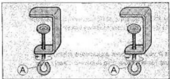
Remove the two table clamps from the accessory box.
Turn screw 'A' in arrow direction as far down as it will go.
natural_image
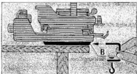
Mechanical assembly diagram showing a clamp and hook mechanism (no text or labels)Ensure that machine is flush with the table edge.
Insert table clamps into slots 'B' underneath the machine.
natural_image
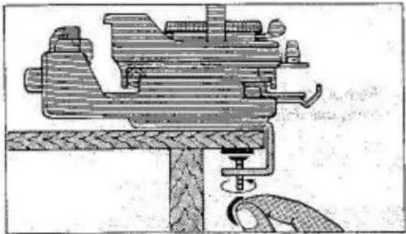
Technical illustration of a mechanical assembly with a tool and base, no visible text or symbolsTighten both clamps firmly by turning screws in arrow direction.
(DO NOT USE FORCE.)
natural_image
Technical diagram of a mechanical assembly with labeled component A (no readable text or symbols)CARRIAGE LOCK PLATE
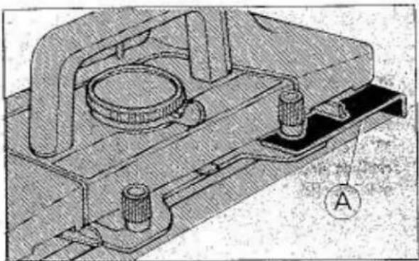
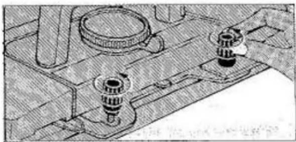
With lock plate 'A' the carriage is secured to the right side of the needle bed in order to eliminate damage during transport.
NOTE: When machine is not in use please secure carriage to needle bed.
natural_image
Technical line drawing of a mechanical assembly with two rotating components (no text or symbols)Loosen both thumb screws by turning them in arrow direction.
natural_image
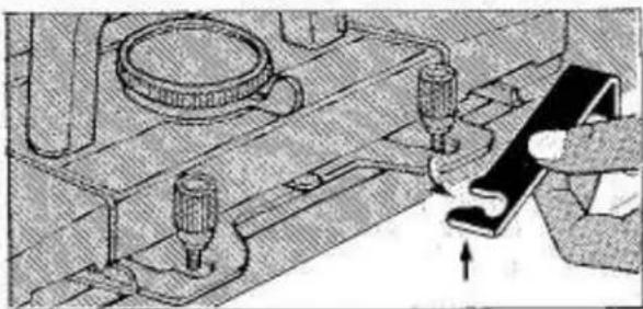
Technical diagram showing mechanical components and a hand interacting with a bracket (no text or symbols visible)Remove lock plate by moving it towards you and lifting it up.
natural_image
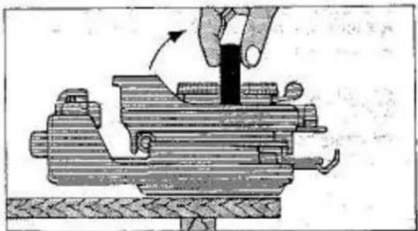
Illustration of a hand operating a mechanical press or fixture with a black cylindrical component, no text or symbols present.Raise carriage handle until it snaps into a locked vertical position.
natural_image
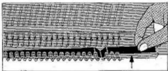
Diagram of a mechanical or structural assembly with layered components and directional arrows (no text or symbols)Remove the cardboard needle protector from the sinker gate.
text_image
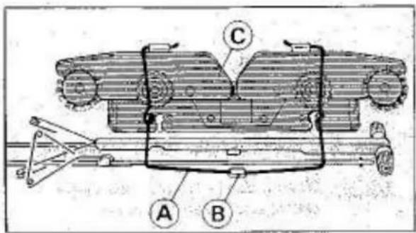
Technical diagram of a mechanical assembly with labeled parts A, B, and CSINKER ARM ASSEMBLY
Release wire spring 'A' from holding bracket 'B' located inside the machine lid and remove sinker arm assembly 'C' from the machine lid.
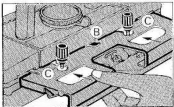
text_image
Technical diagram showing mechanical assembly with labeled components A, B, and C, including directional arrows indicating movement or force.Slide sinker arm assembly under holding bracket 'B' and two thumb screws 'C'.
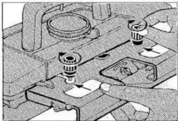
natural_image
Mechanical assembly diagram showing gear and valve components (no text or labels)Push sinker arm assembly as far back as it will go and tighten thumb screws firmly by turning them in arrow direction.
IMPORTANT:
Before proceeding further, check the following two points carefully.
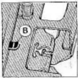
natural_image
Diagram showing a mechanical or architectural component with labeled point B (no readable text or symbols)-
CORRECT
-
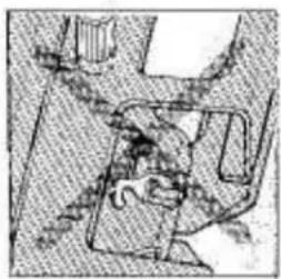
Ensure that holding bracket 'B' is ON TOP of the sinker arm assembly
natural_image
Top-down view of a mechanical assembly or device with no visible text or symbolsINCORRECT
NOT BELOW as shown in illustration.
natural_image
Mechanical component diagram showing a knob and base with labeled parts (no text or symbols beyond labels)-
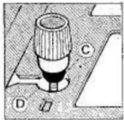
CORRECT
-
Ensure that thumb screws 'C' fit correctly INTO cut-out 'D' of sinker arm assembly
natural_image
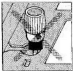
Technical diagram of a mechanical component with no visible text or symbolsINCORRECT
NOT ON TOP of sinker arm assembly as shown in illustration.
SETTING UP THE YARN BRAKE
text_image
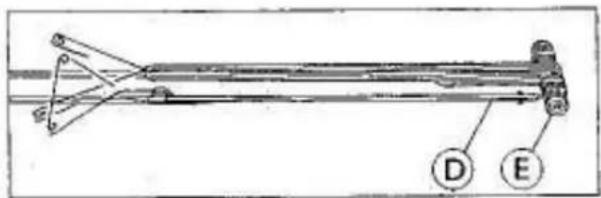
Technical diagram of a mechanical assembly with labeled components D and EYARN BRAKE ASSEMBLY
Remove yarn brake rod 'D' and yarn brake 'E' from machine lid.
text_image
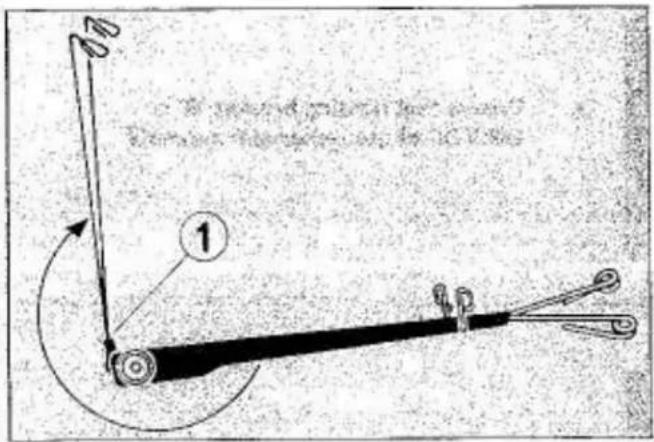
The second position is a point of Elevation displacement for 12.5 kg- Turn the two take-up springs upwards as shown by the arrow until they snap into position.
text_image
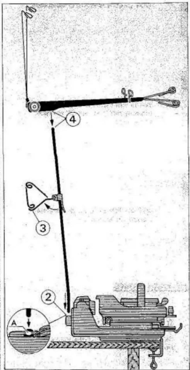
Technical diagram of a mechanical device with numbered components and an inset showing a component labeled A.-
Insert the short bent end of yarn brake rod with yarn clip 'A' facing you into the left side handle bracket socket.
-
Raise the rear yarn guide.
-
Place yarn brake securely onto the yarn brake rod.
THE MAIN PARTS OF THE MACHINE
natural_image
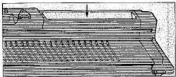
Technical line drawing of a mechanical component with no visible text or symbolsACCESSORY TRAY
text_image
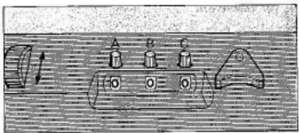
Diagram showing a mechanical or electrical component with labeled parts A, B, C and directional arrows indicating motion or movement.ROW COUNTER
Note: All three numbers on row counter can be adjusted individually by turning plastic knobs 'A', 'B' and 'C' in either direction.
text_image
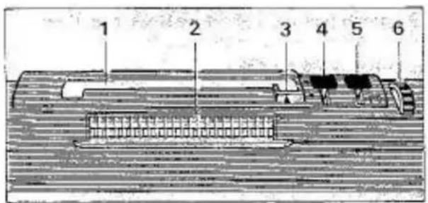
1 2 3 4 5 6PATTERN PANEL
- Punch card insertion slot
- Touch levers
- Card row indicator
- Card release knob
- Pattern variation knob
- Feeding dial
text_image
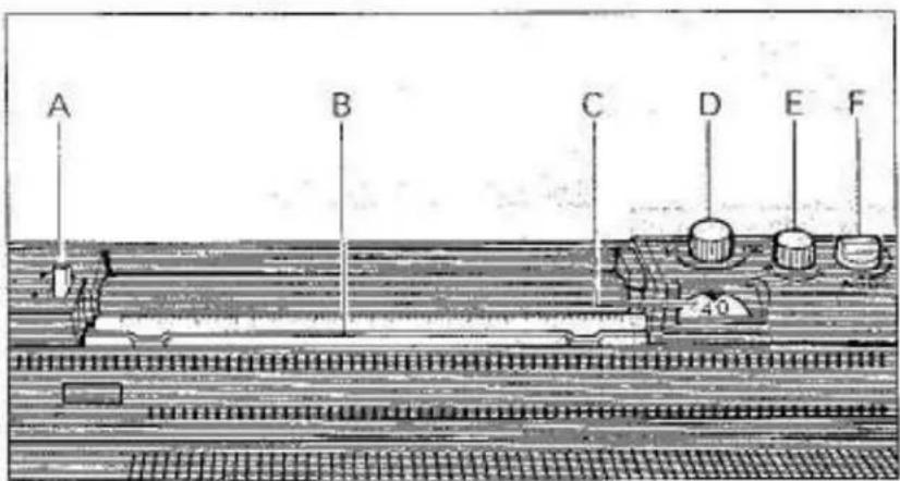
A B C D E F 40KNIT RADAR
a) Paper lock lever
b) Stitch scale holder
c) Row indicator dial
d) Row indicator knob
e) Paper feed knob
f) Row dial
text_image
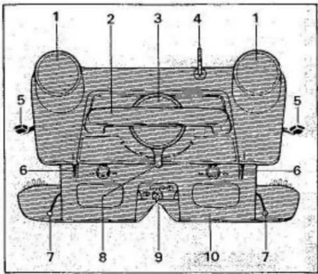
Technical diagram of a mechanical assembly with numbered components for identificationCARRIAGE PARTS
- Pattern memory (left and right)
- Carriage handle
- Tension dial
- Row counter tripper
- Side levers (left and right)
- Front levers (left and right)
- Weaving yarn holder (left and right)
- Cam lever
- Yarn feeder
- Sinker arm
natural_image
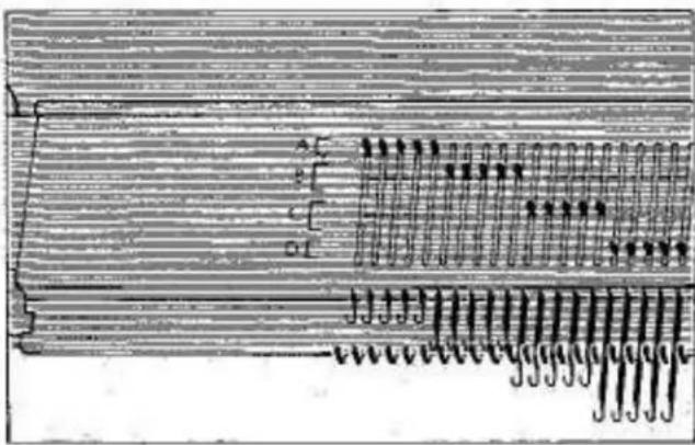
Pure electrical circuit lines without any symbolsOn both the LEFT and RIGHT side of the needle bed you will see markings A, B, C and D. These are the various needle positions used during knitting.
A - non-knitting position.
B - plain knitting and stitch patterns.
C — for end needle when front lever to I.
D - holding position for partial knitting - front levers MUST be set to I.
text_image
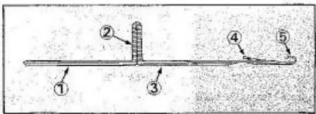
Diagram of a mechanical or electrical component with numbered parts labeled 1 to 5THE LATCH NEEDLE
- Shank
- Butt
- Stem
- Latch
- Hook
HOW STITCHES ARE FORMED
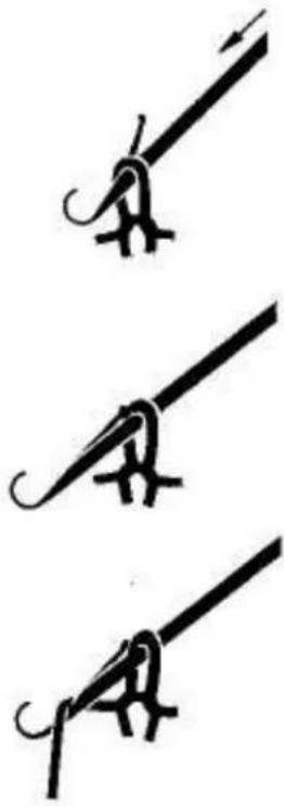
The movement of the latch needle, in and out of the needle bed while knitting, is controlled by the carriage.
natural_image
Three identical line drawings of a stylized bird or creature, possibly a musical instrument, with no text or symbols present.-
As the needle moves out, the stitch automatically opens the latch.
-
The needle moves out further and the stitch slides behind the latch.
-
The yarn is automatically fed onto the hook by the yarn feeder - preparing for a new stitch.
natural_image
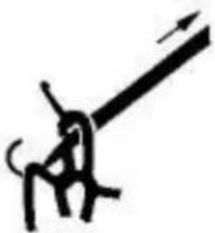
Simple line drawing of a person climbing a long pole with motion lines (no text or symbols)- The needle moves back inside the needle bed, causing the old stitch to close over the yarn inside the hook.
The latch needle will ONLY drop a stitch if there is NO yarn in the needle hook when the needle returns into the needle bed.
natural_image
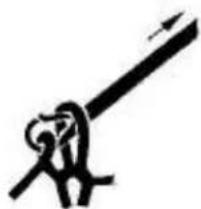
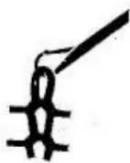
Abstract black line drawing resembling a stylized plant or tool (no text or symbols)- The needle is pulled backwards, causing the old stitch to slide to the front and closing the needle latch.
natural_image
Simple line drawing of a stylized figure with a long handle (no text or symbols)- When the needle is completely pulled back - the old stitch starts to slide over the closed latch and a new stitch is formed in the needle hook.
text_image
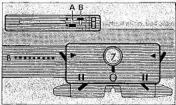
A B 7 II IICARRIAGE ON RIGHT SIDE
| Card release knob 'A' | to ● |
| Pattern variation knob 'B' | to S |
| Right side lever | to ▶ |
| Left side lever | to ▶ |
| Tension dial | to 7 |
| Cam lever | to 0 |
| Right front lever | to II |
| Left front lever | to II |
text_image
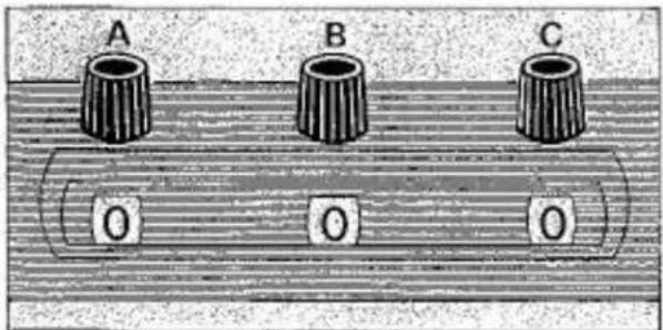
A B C 0 0 0Adjust row counter numbers to '0' by turning knobs 'A', 'B' and 'C'.
text_image
Diagram showing a hand holding a tool with labeled parts and directional arrows, likely illustrating a mechanical or electrical process.CORRECT
ROW COUNTER TRIPPER
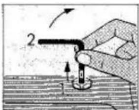
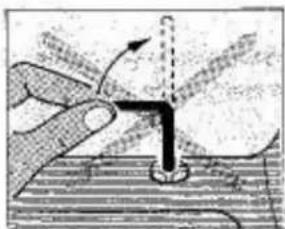
To engage the row counter tripper, hold same in the centre, lift it up and then turn it to the back.
natural_image
Illustration of a hand holding a tool interacting with a vertical pipe or tube, no text or symbols presentINCORRECT
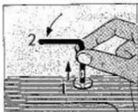
DO NOT hold row counter tripper on the side and then turn, as shown in illustration, as this will damage the row counter tripper holding bracket.
text_image
Diagram showing a hand holding a tool with labeled parts and directional arrows, likely illustrating a mechanical or electrical process.NOTE:
To disengage, hold row counter tripper in the centre, lift it up and then turn it to the side.
Empinal Knitmaster
10
PREPARATION OF YARNS
As the preparation of yarns is very important, please read the next chapter very carefully.
The machine is designed to knit a wide range of yarns.
In the beginning, however, we recommend you start off with a new ball of medium, 4-ply yarn - NOT WITH LEFTOVERS.
As you become accustomed to machine knitting you will be able to use all types of yarns - so please be patient.
text_image
1 2 3-
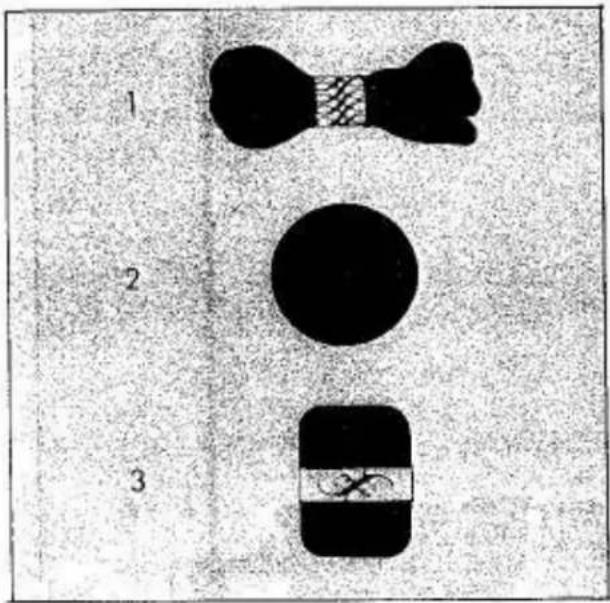
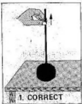
It is impossible to knit from a hank of yarn. You will have to rewind it using a yarn winder.
-
This hand wound ball is not suitable for machine knitting. It will roll around and become tangled. You MUST rewind it using a yarn winder.
-
It is not recommended that you use a pull skein of yarn as it is impossible to knit with the outside end of the yarn. We do not recommend pulling the yarn from the centre as the yarn does not always draw smoothly and there may be knots.
natural_image
Technical line drawing of a mechanical device with no visible text or symbolsAUTOMATIC YARN WINDER
USEFUL OPTIONAL EXTRA ACCESSORY
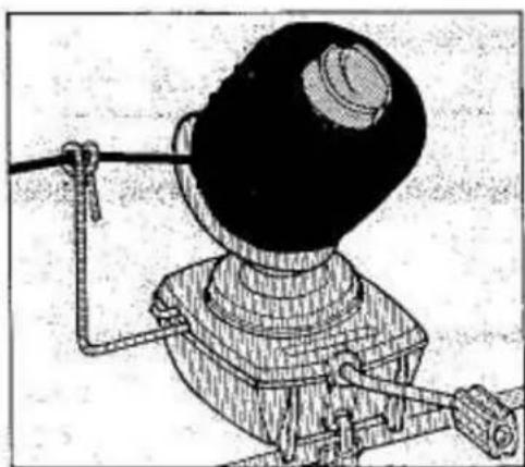
The yarn winder will wind the yarn speedily and perfectly ready for machine knitting. It saves a great deal of time by winding the yarn into a ball in only a few seconds.
text_image
1. CORRECT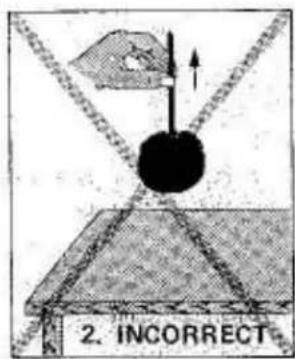
text_image
2. INCORRECTIMPORTANT TEST
When the yarn is pulled from the centre of the ball - the thread must come out freely without lifting the ball from the table - see illus. 1.
THREADING THE MACHINE
text_image
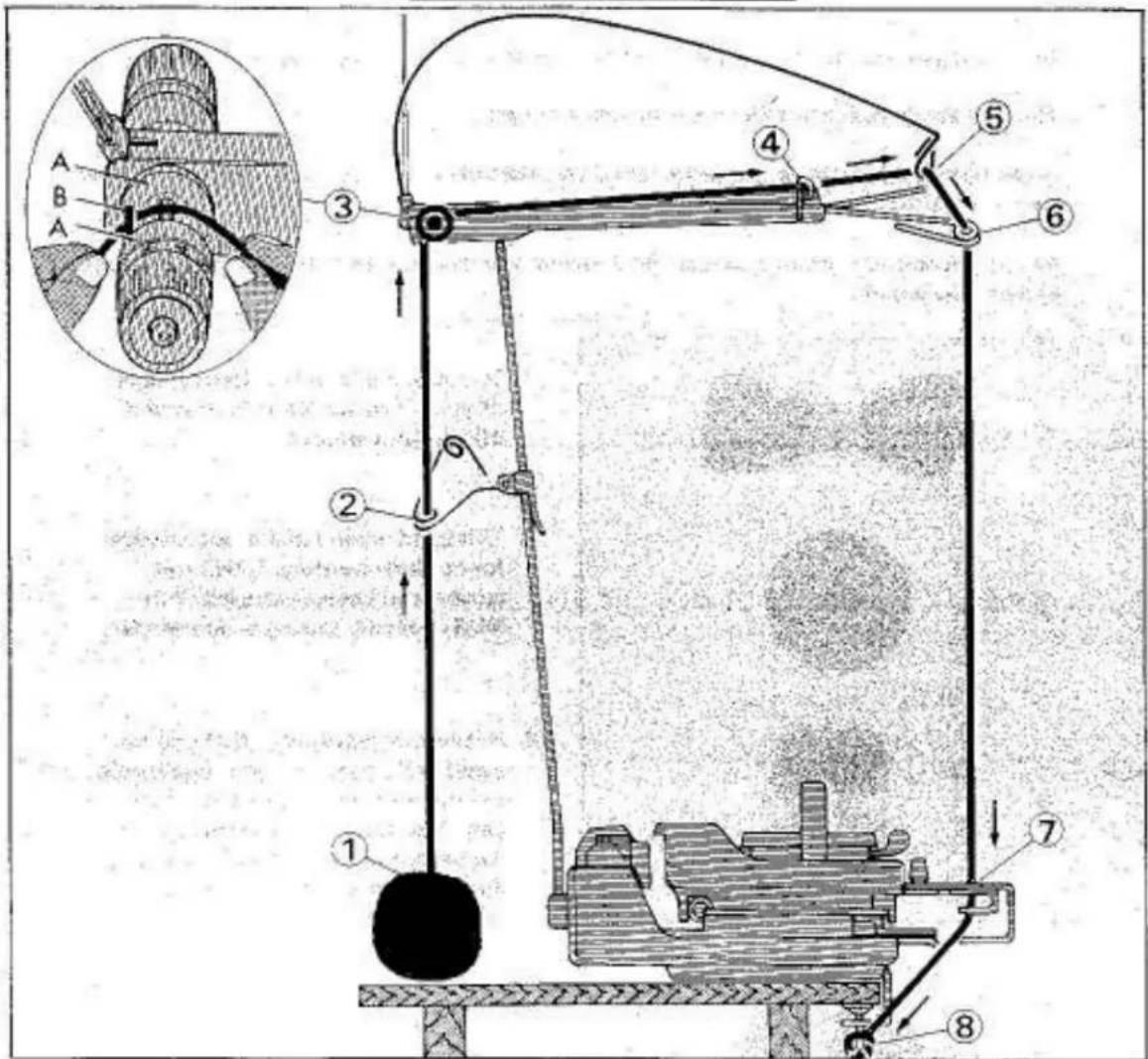
Technical diagram of a mechanical device with numbered components and an inset showing a cross-section view of a mechanical assembly.CARRIAGE ON RIGHT SIDE.
- Pull the yarn end out of the centre of the ball ensuring that the yarn comes out easily without lifting the ball from the table.
- Thread yarn through the yarn guide eyelet.
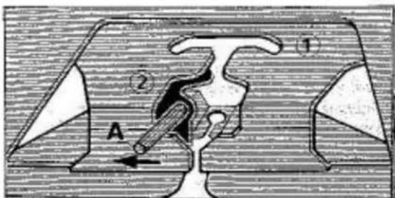
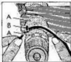
- Place the yarn between the two tension discs 'A' and ensure that yarn lies underneath of pin 'B'.
- Thread yarn through yarn guide eyelet.
- Thread yarn through yarn guide eyelet on take-up spring.
- Thread yarn through yarn guide eyelet.
text_image
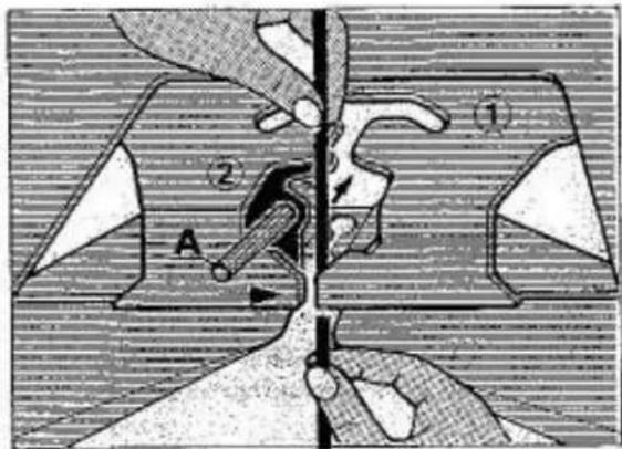
Diagram of a mechanical or electrical component with labeled parts and directional arrow, marked with numbers ① and ②.- Open the yarn feeder by moving guide pin 'A' to the left.
text_image
Technical diagram showing mechanical assembly with labeled parts and directional arrowsHold the yarn with both hands and slide it into the yarn feeder.
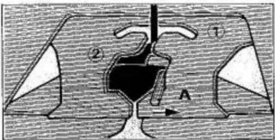
Close the yarn feeder by moving guide pin 'A' to the right.
natural_image
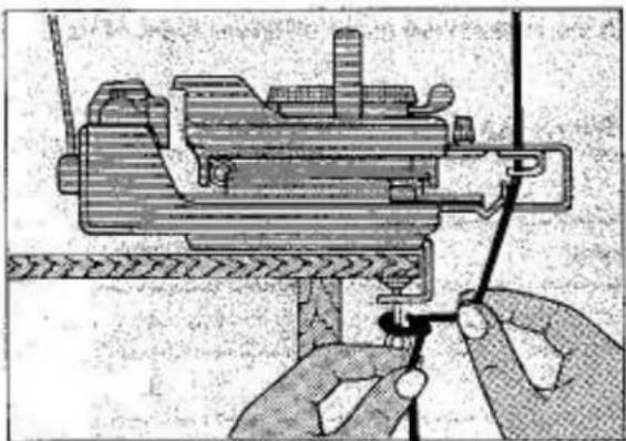
Illustration of hands operating a mechanical device with a tool, no visible text or symbols- Fasten end of yarn onto the right side table clamp.
text_image
Diagram of a mechanical or fluid system with labeled components and directional arrows, including symbols ①, ②, and A.IMPORTANT
Before starting to knit ensure
a) Yarn lies correctly in yarn feeder.
text_image
A B Ab) Yarn is placed BETWEEN discs 'A' and UNDER pin 'B'.
text_image
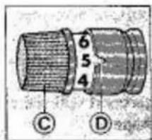
6 5 4 C Dc) Yarn brake tension is adjusted correctly by turning plastic dial 'C' until required number corresponds with cut-out 'D' on tension disc.
Empirel-Knutmanten -13
TENSION AND STITCH SIZE
JUST AS IN HAND KNITTING, IT IS IMPORTANT TO HAVE THE RIGHT STITCH SIZE FOR THE YARN THAT YOU USE.
text_image
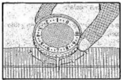
Diagram illustrating a mechanical or electrical process with labeled components and directional arrows indicating motion or movement.In the centre of the carriage is the tension dial.
The tension dial has 30 different tension settings and you will be able to choose the right stitch size most suitable for the yarn used.
It is quite impossible to tell you which tension setting to use as there are many different types of yarn available.
Before starting to knit a garment it is essential and necessary to knit a tension swatch. Below you will find a general tension guide.
| Yarn Type | Yarn Brake | Tension Dial |
| Lightweight | 4 - 7 | 1 - 4 |
| Medium | 3 | 5 - 8 |
| Heavy | 1 - 2 | 9 - 10 |
NOTE: Sweaters are usually knitted one or even two points looser than you would use for a skirt. The reason is that a sweater is comfortable when it has more stretch but a skirt will stretch out of shape unless the tension is a little tighter.
natural_image
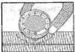
Diagram of a mechanical or electrical component with no visible text, numbers, or symbolsWhen the tension dial is set to 0 - the TIGHTEST tension is obtained (smallest stitch).
natural_image
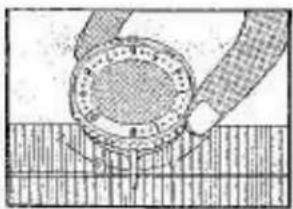
Diagram of a mechanical assembly or cleaning process with no visible text or symbolsWhen the tension dial is set to 10 - the LOOSEST tension is obtained (largest stitch).
natural_image
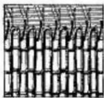
Pure grid pattern with no text, numbers, or symbolsIF YOUR TENSION IS TOO TIGHT -
it will be difficult, or even impossible to knit and you will use more yarn, thus wasting money and your knitwear will be hard and uncomfortable to wear.
IF YOUR TENSION IS TOO LOOSE -
your knitted garment will either have no shape or will very soon lose its shape.
natural_image
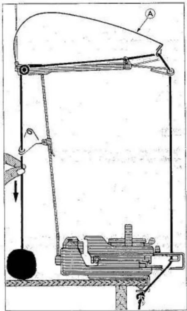
Mechanical device diagram showing a lifting mechanism with pulleys and weights (no text or symbols)d) Before starting to knit, pull the yarn down at the back of the yarn brake, in arrow direction, until all slack yarn has been taken up and take-up spring 'A' is nearly in a horizontal position.
YOU ARE NOW READY TO CAST ON.
CAST-ON
natural_image
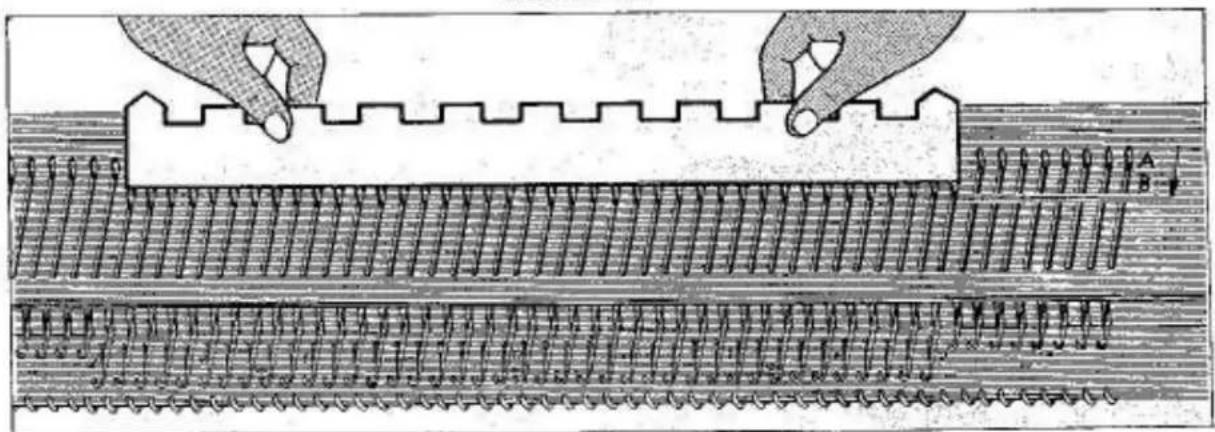
Technical illustration of a mechanical assembly with two hands adjusting a stepped component (no text or symbols present)Remove the 1x1 needle pusher from the accessory box.
Use the straight edge of the 1x1 needle pusher and bring 20 needles on each side of centre '0' from 'A' (non knitting) position to 'B' (knitting) position.
You now have 40 needles in 'B' (knitting) position.
ALL OTHER NEEDLES MUST BE IN 'A' (non knitting) POSITION.
text_image
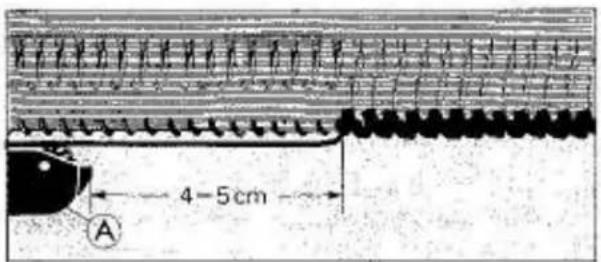
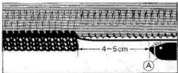
4-5cm AKnit 1 row by moving carriage slowly from right to left until sinker arm plate 'A' has passed the last needle in 'B' position by approximately 4 to 5 cm.
natural_image
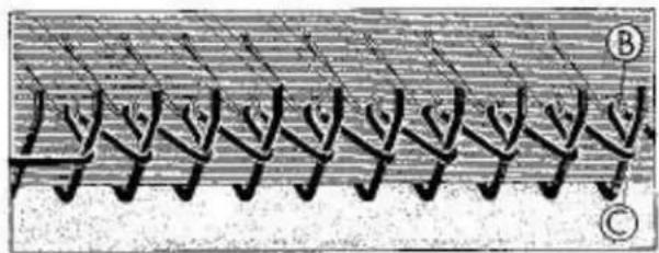
Pure diagram of repeating abstract shapes with no text or symbolsNOTE:
An even loop has been formed between needle hook 'B' and sinker gate pin 'C'.
text_image
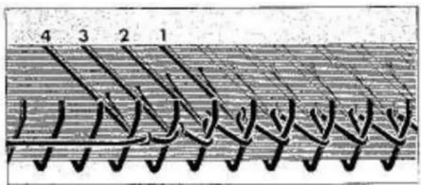
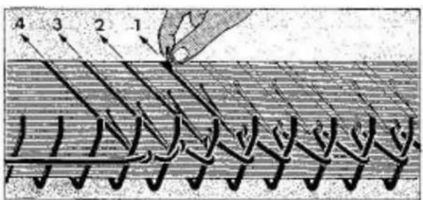
4 3 2 1When knitting the first row it might happen that the loops get smaller towards the left side (see illus. needles 1,2,3 and 4.)
This is incorrect and can be easily corrected.
natural_image
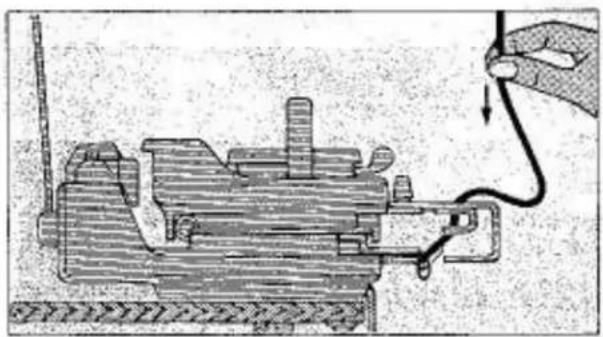
Mechanical assembly diagram showing a hand holding a wire connected to a motor (no text or labels visible)CORRECTION:
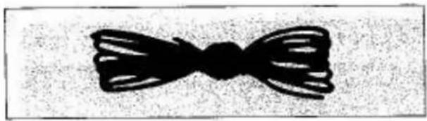
Hold yarn above yarn feeder and pull it down to form a loop.
text_image
4 3 2 1Starting from the smallest loop furthest away from the carriage, in this instance needle No. 1, push the needles with small loops back to 'B' position - ONE BY ONE.
natural_image
Simple black bowtie illustration on textured background (no text or symbols)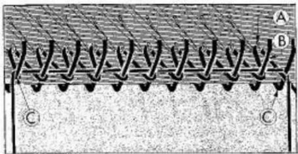
text_image
A B C C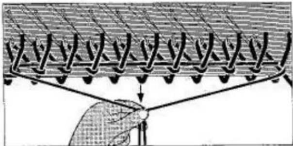
text_image
Diagram illustrating a mechanical or electrical system with labeled components and directional arrows, possibly representing a system or process.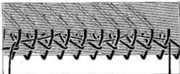
natural_image
Abstract pattern of repeating black shapes on a textured gray background (no text or symbols)INCORRECT
text_image
4-5cm ANYLON CORD
Remove nylon cord from the accessory box, open it and check that there are no knots in the nylon cord before using same as otherwise you cannot pull it out of the knitting after casting on.
Lay the nylon cord across the yarn loops between needle hooks 'A' and sinker gate pins 'B'.
Pass it around and down the last sinker gate pin 'C' on left and right side of needles with loops.
Hold both ends together and pull down firmly so that the nylon cord is below the needle hooks.
Before knitting ensure that nylon cord lies correctly across the loops and is pulled down sufficiently as otherwise it will become loose and entangled.
Knit 5 rows stopping with carriage on the right side.
ENSURE AT ALL TIMES THAT SINKER ARM PLATE 'A' HAS PASSED THE LAST KNITTED NEEDLE BY APPROXIMATELY 4 TO 5 CM BEFORE CHANGING DIRECTION.
natural_image
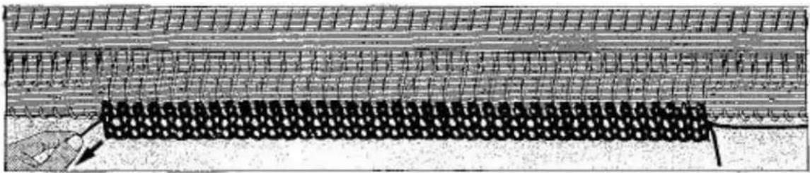
Diagram of a road with a moving car and a grid-patterned lane, no text or symbols presentPull out nylon cord either to the left or right side and unfasten yarn end from right side table clamp.
natural_image
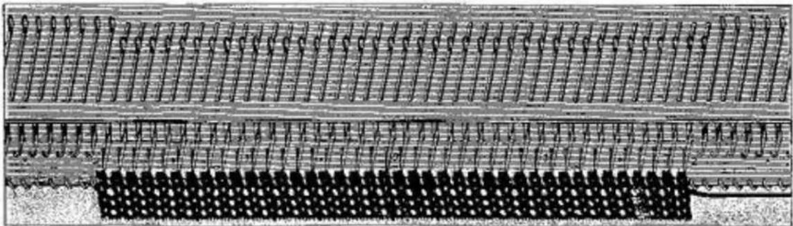
Pure electrical circuit lines without any symbolsContinue knitting until your first ball of yarn has been knitted — this is the best way to get the right rhythm for machine knitting and to feel confident with your new knitting machine.
HOW TO REMOVE THE KNITTING FROM THE MACHINE WITHOUT CASTING OFF
natural_image
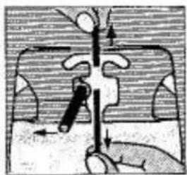
Diagram of a mechanical or electrical component with directional arrows indicating movement (no text or symbols)- Open feeder; break off main yarn above feeder.
natural_image
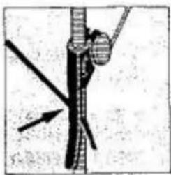
Close-up of a rope knot with a pointed tip and directional arrow (no text or symbols)- Hook yarn end into yarn clip on uprod.
Empisol-Knutmester 18
natural_image
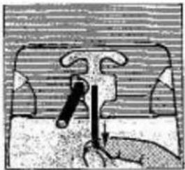
Illustration of a hand holding a tool or device with a curved handle and a vertical bar, no visible text or symbols.- Pull yarn out of feeder and let it hang loosely on the side of the fabric.
natural_image
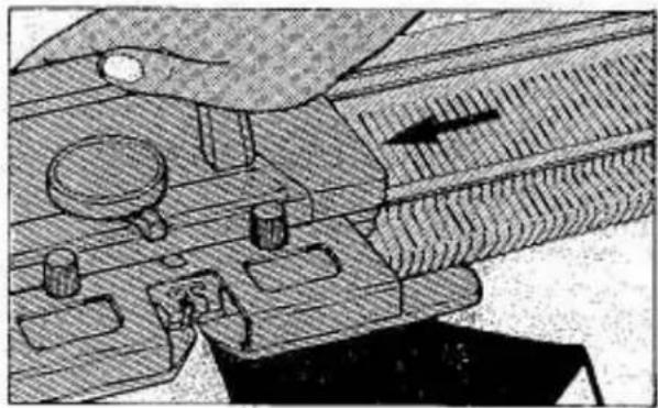
Mechanical assembly diagram showing internal components and motion direction (no text or labels)Remove tension swatch from machine by moving carriage across knitted fabric.
The knitting comes away automatically from the needles, but it will have an open edge.
YOU HAVE NOW COMPLETED THE MOST IMPORTANT PART OF MACHINE KNITTING.
YOU ARE NOW MACHINE KNITTING
IF YOU HAVE HAD ANY DIFFICULTY IN KNITTING THE FIRST ROWS, CHECK TO SEE IF—
- The carriage ALWAYS passes ALL the needles in KNITTING position before returning to knit the next row.
- The yarn is suitable for your tension setting.
- The yarn is threaded correctly.
- The yarn is properly wound into a ball suitable for machine knitting.
REMEMBER — ALWAYS move the carriage past all the needles in knitting position before changing direction for the next row.
BUT — moving the carriage TOO FAR beyond the knitting, results in loose yarn tension, and the yarn will tangle around the brushes below the Sinker Arm which will cause the carriage to jam or the yarn to break.
PATTERN KNITTING WITH A PUNCH CARD
The following basic stitch patterns can be knitted on the
Empisal-Knitmaster®
326 Knitting Machine
natural_image
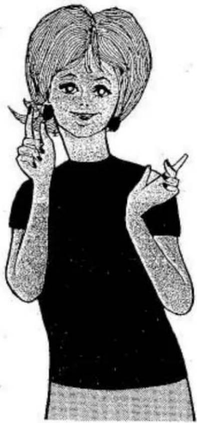
Illustration of a person holding scissors and pointing at her finger (no text or symbols present)*SINGLE MOTIF PATTERNS
* LACE PATTERNS
*TUCK STITCH PATTERNS
* PUNCH LACE PATTERNS
*SLIP STITCH PATTERNS
*FAIR ISLE PATTERNS
*PLAITING PATTERNS
*WEAVING PATTERNS
natural_image
Illustration of a fan-shaped arrangement of paper sheets with dotted outlines, no text or symbols presentTHE PUNCH CARD
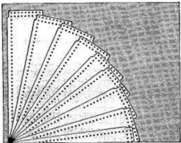
20 Pattern Cards are supplied with the machine. The cards are numbered from 1 - 20.
IMPORTANT: Do not fold or bend card.
text_image
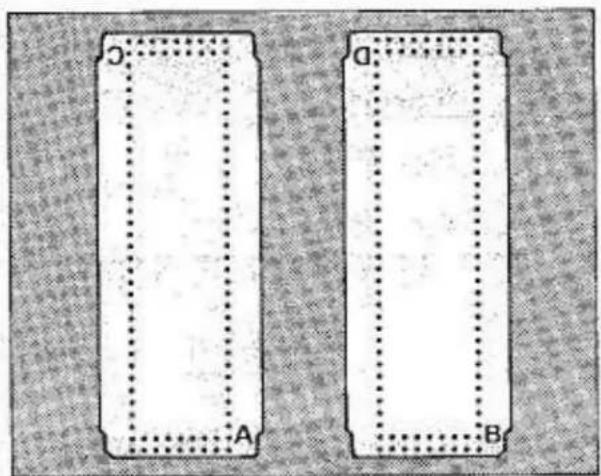
C A D BEach card can be used in four different ways and are marked 'A', 'B', 'C' and 'D'.
'A' indicates the basic pattern.
If 'B', 'C' or 'D' side of the card is inserted into the pattern panel, direction of pattern can be changed.
text_image
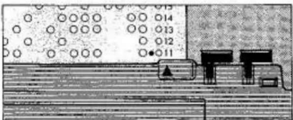
7 6 5 4 3 2 1 60 39 58 ACOLOUR CHANGE INDICATION
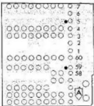
Card No. 5, 6-03 and 19-03 have red dots next to a number indicating that yarn colour can be changed.
natural_image
Illustration of a mechanical setup with rollers, a pump, and a tank (no text or symbols)When red dot appears above card row indicator mark ▲ you can change colour by removing main yarn from feeder No. 1 and threading different colour yarn into main feeder No. 1.
IN THE PATTERN BOOK YOU WILL FIND THE FOLLOWING PATTERN CARDS
text_image
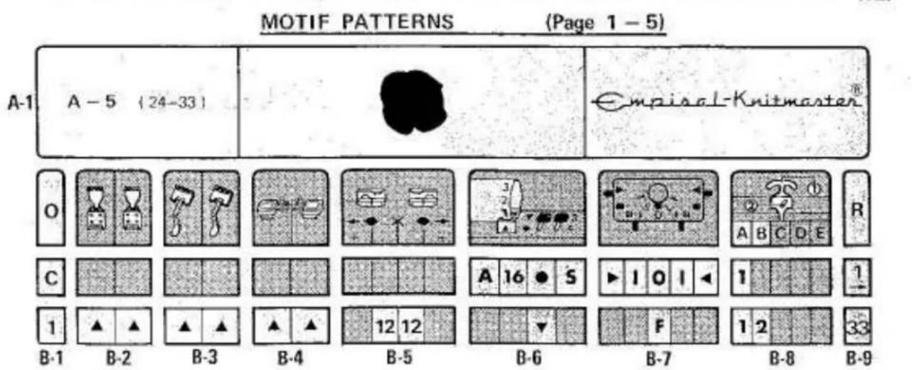
MOTIF PATTERNS (Page 1 - 5) A-1 A - 5 (24-33) Empisal-Knitmaster® O C 1 B-1 B-2 B-3 B-4 B-5 B-6 B-7 B-8 B-9 R 1 1 2 33TUCK PATTERNS (Page 6-13)
SLIP PATTERNS (Page 14 – 18)
LACE PATTERNS (Page 20 - 21)
FAIR ISLE PATTERNS (Page 23 - 29)

text_image
Empisol-Knitmaster® B—— 0 A·1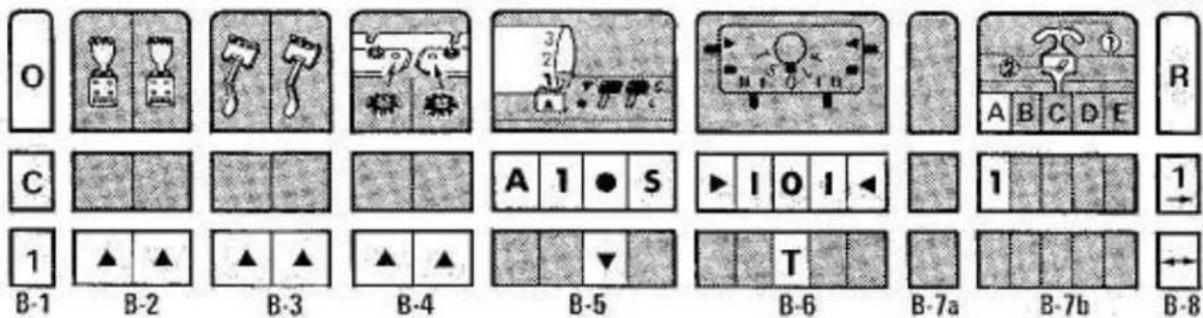
text_image
O C B-1 B-2 B-3 B-4 B-5 B-6 B-7a B-7b B-8PLATTING PATTERNS (Page 19)

text_image
Empirical-Knitmaster® B—— 0 A-1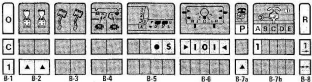
text_image
O C B-1 B-2 B-3 B-4 B-5 B-6 B-7a B-7b B-8 R P A B C D E 1 1 B-8
WEAVING PATTERNS (Page 30 - 32)
text_image
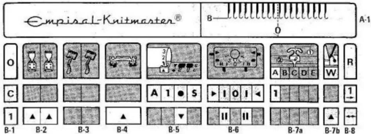
Empisal-Knitmaster® B— O A-1 O C B-1 B-2 B-3 B-4 B-5 B-6 B-7a B-7b B-8EXPLANATION OF PATTERN CARD SYMBOLS
text_image
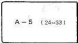
A - 5 (24-33)A-1 PUNCH CARD REFERENCE NO.
A-5
indicates punch card reference No. In this instance use card No. 5 side 'A'
(24-33)
indicates how many stitches and rows to one complete pattern. Left number stands for STITCHES Right number stands for ROWS.
text_image
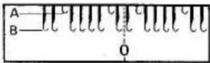
A B OA-1 NEEDLE ARRANGEMENT
Select required needles as shown in this column.
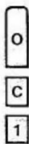
B-1 OPERATION PROCEDURE
'C' indicates memorise pattern into memory drums.
Numbers indicate operation procedure.

B-2 CLAW WEIGHTS
Triangle (▲) mark indicates that claw weights should be used.
natural_image
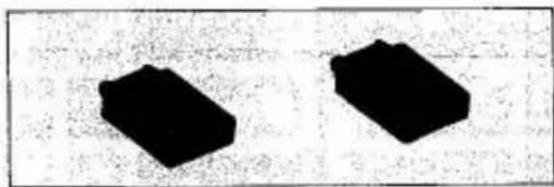
Two black rectangular blocks on a textured background, no text or symbols visibleRemove the two claw weights from the accessory box and attach to fabric when knitting double welts and patterns.
text_image
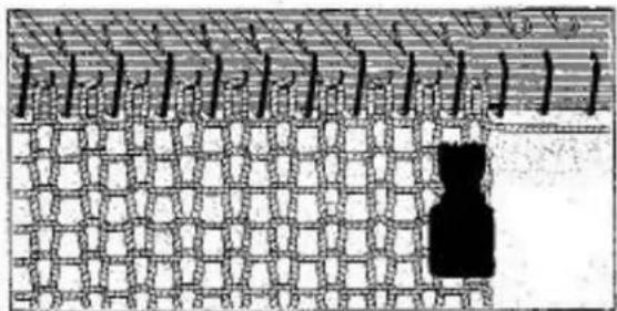
Diagram showing a grid structure with labeled points and a black silhouette in the bottom-right corner, possibly indicating a pattern or feature.Fit one each claw weight on the left and right side of knitted fabric.
For MOTIF KNITTING hang the claw weights on the inner side of motif pattern.
After knitting 30–40 rows move claw weights upwards close to the needles.
B-3 YARN SEPARATOR
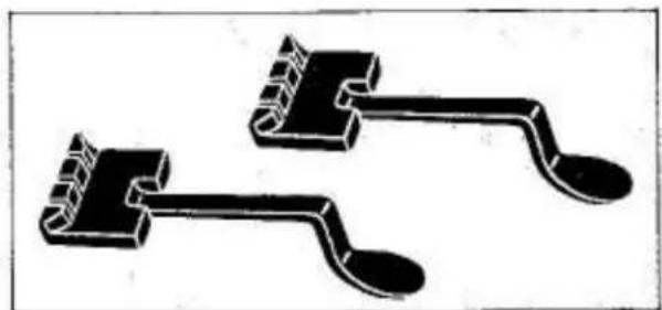
FINGERS
Triangle (▲) mark indicates that yarn separator fingers should be used.
natural_image
Two black 3D-rendered mechanical components with curved ends and notches, resembling tools or sensors (no text or symbols)Remove yarn separator fingers from accessory box.
text_image
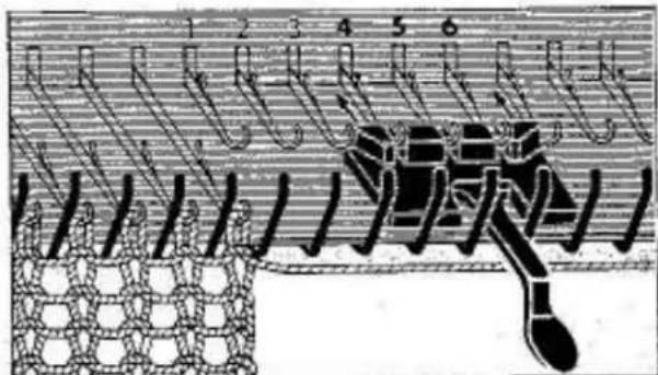
Technical diagram showing a mechanical assembly with numbered components and a central component, likely illustrating a gear or cam mechanism.Insert under the 4th, 5th and 6th non-working needle on left and right side of knitted fabric the yarn separator finger and push backwards as far as it will go. (See illustration).
ENSURE THAT OVAL SIDE FACES DOWNWARDS.
text_image
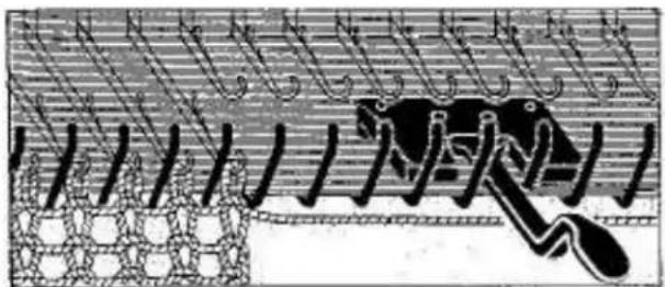
Historical diagram showing a mechanical or electrical component with labeled parts and structural elementsINCORRECT
DO NOT insert yarn separator finger with oval part facing upwards.
natural_image
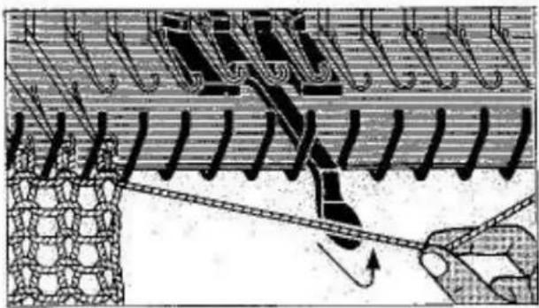
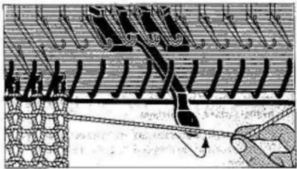
Diagram of a mechanical or electrical component with hooks and a chain, showing motion paths (no text or symbols)When knitting TUCK and TUCK LACE patterns yarn must lie on top of yarn separator finger.
natural_image
Technical illustration of a mechanical assembly with gear and chain, showing no text or symbolsWhen knitting MOTIF patterns yarn must be arranged as follows:
MAIN YARN
must lie on top of yarn separator finger.
SECOND YARN
must lie underneath of yarn separator finger.
text_image
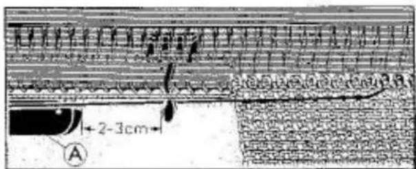
2-3cm AIMPORTANT:
Ensure that sinker arm plate 'A' has passed the yarn separator finger by approximately 2 - 3 cm before knitting next row.
B-4a MAGIC CAM
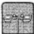
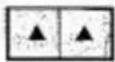
The triangle (▲) mark indicates that magic cam must be attached to carriage.
natural_image
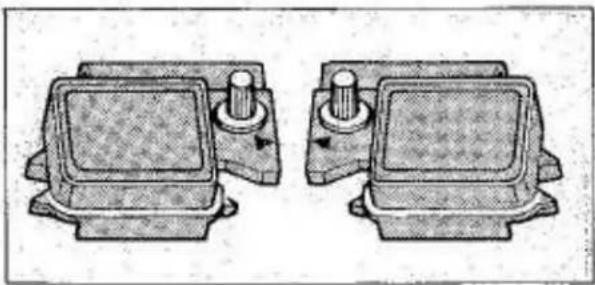
Two identical mechanical components with cylindrical ports and mounting brackets, shown from top and side views (no text or symbols)Remove the two magic cams (left and right) from the accessory box and attach to the carriage as follows:
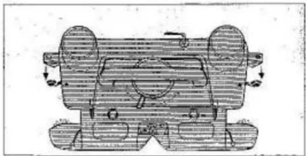
natural_image
Technical line drawing of a mechanical component with no visible text or symbolsSet both side levers . . . . . . to
natural_image
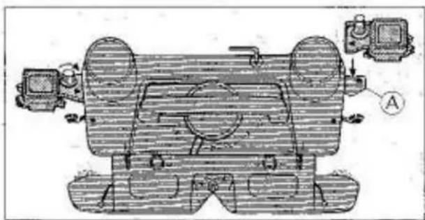
Technical line drawing of a mechanical assembly with labeled components (no readable text or symbols)Place left and right magic cam onto extension plates 'A' ensuring that the triangle mark on magic cam is facing you and corresponds with triangle mark on carriage.
Fasten magic cam securely to extension plates 'A' by turning the knurled nuts in clockwise direction.
natural_image
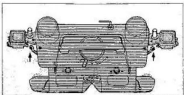
Technical line drawing of a mechanical component with no visible text or symbolsSet both side levers . . . . . . to
IMPORTANT: DO NOT SET THE TENSION DIAL 'A' HIGHER THAN 7 DURING MOTIF KNITTING.
B-4b POINT CAM
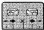
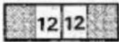
The numbers indicate position of point cam.
natural_image
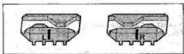
Two technical diagrams of mechanical components with labeled sections L1 and R (no text or symbols beyond labels)Remove the two point cams (left and right) from the accessory box and place on needle bed as follows:
LEFT POINT CAM (yellow colour)
RIGHT POINT CAM (red colour)
text_image
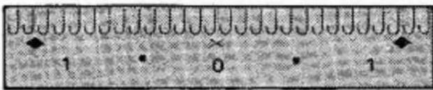
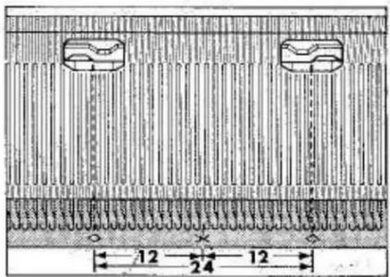
1 0 1NOTE: On the front of the needle bed underneath the needles is a vinyl tape with the following markings:
X indicates centre of pattern
indicates width of pattern
0-100 on left and right side of centre '0' indicates number of needles.
text_image
12 24 12Select the nearest two (◆) marks where you would like to knit the motif pattern and place the left and right point cams on the needle bed behind the needle butts of needles in 'B' position.
LEFT POINT CAM:
Black line must be in centre of (◆) mark between 12th and 13th needle from the centre of (X) mark.
RIGHT POINT CAM:
White line must be in centre of (◆) mark between 12th and 13th needle from the centre of (X) mark.
natural_image
Diagram of a mechanical or electrical component with labeled parts A and B, showing no readable text or symbols.IMPORTANT:
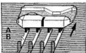
Ensure that studs 'A' fit correctly into needle bed grooves 'B'.
Before starting to knit push both point cams back as far as they will go.
natural_image
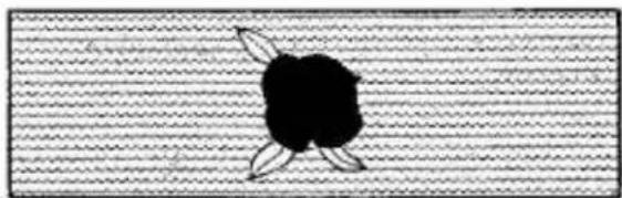
Simple black-and-white illustration of a fruit with three leaves on a textured background (no text or symbols)If point cams are placed as in above illustration you will be able to knit one motif pattern.


natural_image
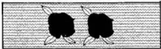
Pure electrical circuit lines without any symbolsYou can knit more than one motif pattern in one row by placing the point cams further apart.
NOTE: Ensure that black line on left point cam and white line on red point cam is in centre of diamond ♦ mark.
natural_image
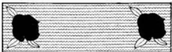
Two black silhouette figures with leaf-like arms, standing on a textured background (no text or symbols)If point cams are placed as in above illustration you will be able to knit two motif patterns next to each other.

natural_image
Two identical diagrams showing a mechanical or electrical component with spring-like elements and cross marks, no text or symbols present.You can also knit more than one motif pattern in different places by simply placing the second point cam set in a different position on the needle bed between two ◆----◆marks.
natural_image
Two black cartoon characters with leaves on a textured horizontal background (no text or symbols)If point cams are placed as in above illustration you will be able to knit two motif patterns in different places.
text_image
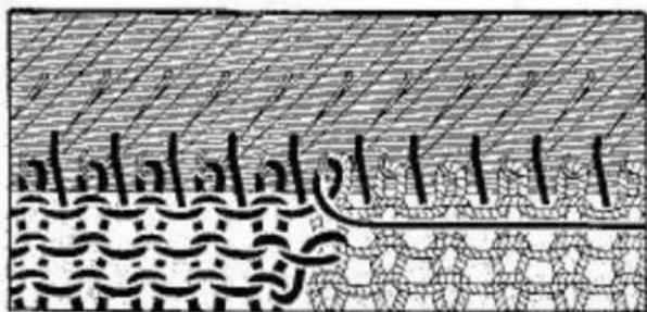
Arabic text with decorative border and stylized characters, possibly from a historical or literary document.For a better finish when doing single motif patterns we recommend the following:
After each row is knitted, wind contrast yarn around needle hook of first needle (side nearest the carriage) adjacent to last stitch of motif knitted.
B-4 ROUND BRUSHES
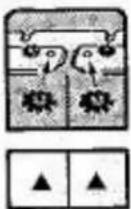
The triangle (▲) mark indicates that the round brushes must be attached to the sinker plates.
natural_image
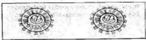
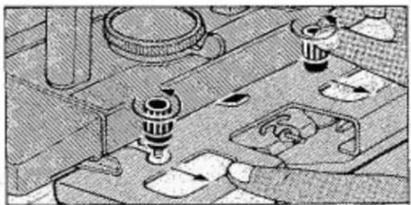
Two identical circular emblem designs with radiating lines, no text or symbols presentRemove the two round brushes from the accessory box and attach to the sinker plates as follows:
natural_image
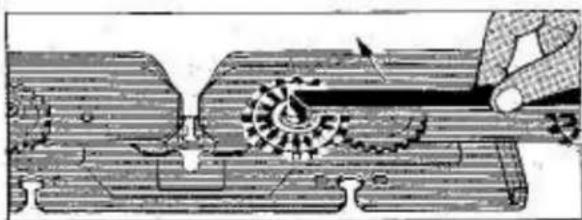
Mechanical assembly diagram showing components like gears and levers (no text or labels)Loosen both thumb screws and remove sinker arm assembly from the carriage.
text_image
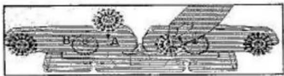
Bras ATurn sinker arm assembly upside down and screw the two round brushes into holes 'A' located next to fabric gears 'B'.
natural_image
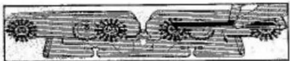
Technical line drawing of a mechanical assembly with gears and shafts (no text or symbols)Use a screwdriver or the short bent end of the needle retaining bar pusher to tighten screws securely. DO NOT USE FORCE.
natural_image
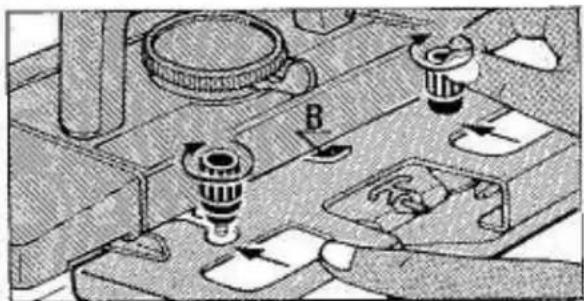
Mechanical assembly diagram showing a motor, gear, and housing components (no text or labels)Fit sinker arm assembly to carriage and tighten knurled nuts firmly ensuring that holding bracket 'B' is on top of sinker arm assembly and both knurled nuts fit correctly into cut-out of sinker arm.
natural_image
Technical illustration of a mechanical assembly with gears and a tool (no text or symbols)For plain or other pattern knitting, remove the round brushes from the sinker arm assembly.
B-4 WEAVING BRUSH
ASSEMBLY

The triangle (▲) mark indicates that the weaving brush assembly must be attached to the carriage.
natural_image
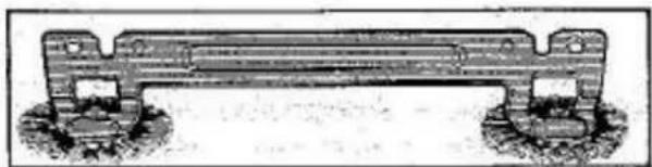
Technical line drawing of a mechanical support structure (no text or symbols)Remove weaving brush assembly from accessory box and attach to carriage as follows:
text_image
A
natural_image
Abstract geometric pattern with diagonal lines and shaded regions (no text or symbols)If you attach weaving brush during knitting.
Carriage on right side.
Open feeder by moving pin 'A' to the left. Remove main yarn from feeder and lay it around yarn clip on right side of machine.
natural_image
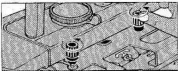
Technical illustration of mechanical components on a workbench (no text or symbols visible)Loosen both thumb screws by turning them in arrow direction.
natural_image
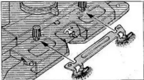
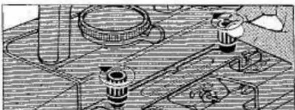
Mechanical assembly diagram showing gear and cam mechanism (no text or labels)Instal the weaving brush on top of the sinker arm assembly and under the two thumb screws.
natural_image
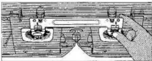
Illustration of a hand operating a mechanical device with no visible text or symbolsEnsure weaving brush and sinker arm assembly fits correctly.
natural_image
Technical illustration of mechanical components and assembly (no visible text or symbols)Tighten both thumb screws firmly.
Remove main yarn from yarn clip; thread into feeder; close feeder.
B-5 PATTERN PANEL
and PUNCH CARD
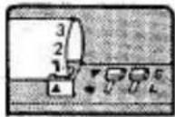

A-1 indicates that 'A' side of card must be inserted into pattern panel slot.
- indicates that card release knob must be set to (●) mark.
S indicates that pattern variation knob must be set to 'S' mark.
text_image
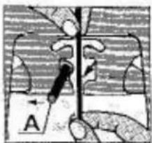
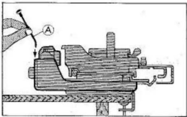
Technical diagram showing mechanical assembly with labeled component A and tool interacting with a workpieceRemove card guide pin 'A' from the accessory box and insert it into the hole located at the back of the pattern panel.
text_image
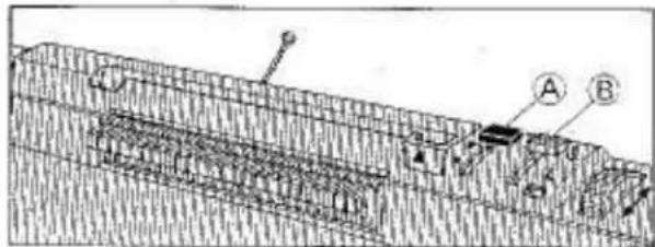
Technical diagram showing a cross-section of a layered geological or structural structure with labeled components A and B.Set card release knob 'A' to▼ Set pattern variation knob 'B' to S
natural_image
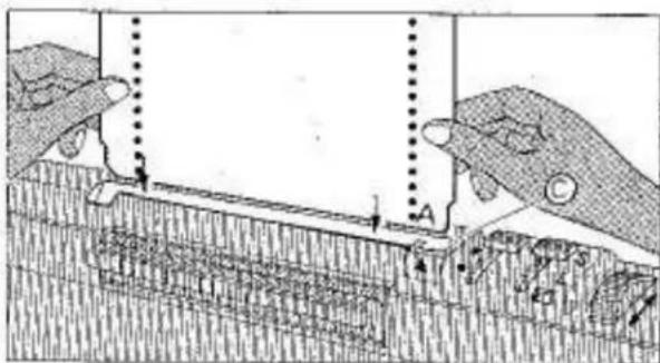
Technical diagram showing two hands operating a mechanical or structural component with labeled points A and C (no readable text or symbols)Remove card from vinyl envelope. Holding card straight with the letter 'A' on the bottom right hand corner facing you, insert it into the pattern panel slot 'C' and push it down slightly.
text_image
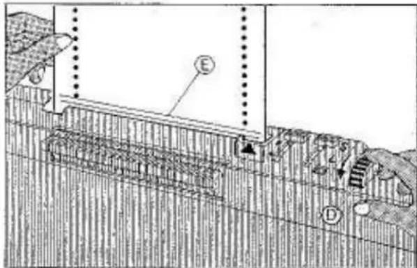
Technical diagram showing cross-section of a layered structure with labeled components E and D, likely illustrating geological or engineering features.Turn feed dial 'D' slowly towards you and at the same time check that the red indication lines 'E' on the card are parallel with the front of the pattern panel.
natural_image
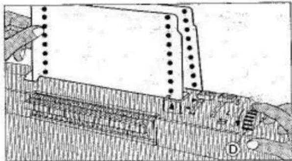
Technical diagram of a mechanical assembly with no visible text or symbolsContinue turning feed dial 'D' towards you until the card comes out at the back of the pattern panel and front and back edge of card are in line.
natural_image
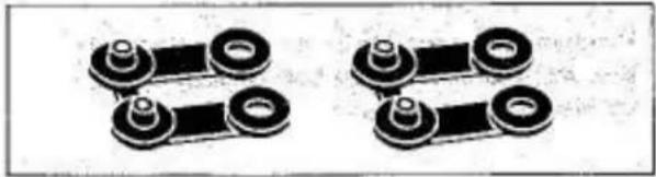
Two identical mechanical link components with circular ends and flanges, shown in two different orientations (no text or symbols)Remove two card clips from the accessory box.
natural_image
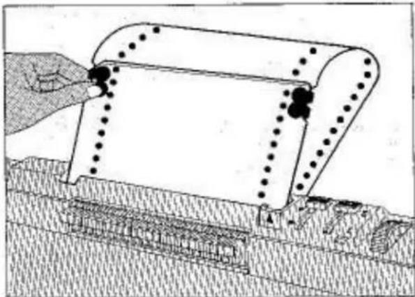
Diagram of a dam or retaining structure with structural elements and water levels (no text or symbols)Overlap the ends of the card with the letter 'C' on top.
Line up the 2 holes on each side.
Insert card clips and join card ends by pressing clips together.
natural_image
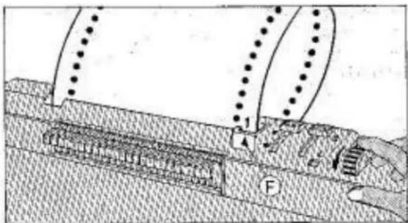
Diagram of a mechanical or structural assembly with labeled components (no readable text or symbols)Turn feed dial until No. 1 printed on the card appears above the triangle mark 'F' on pattern panel.
NOTE: No, 1 is always the beginning of a pattern.
natural_image
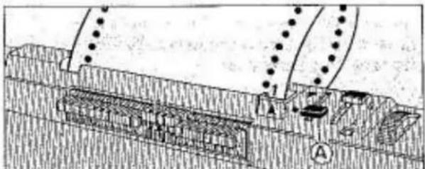
Cross-sectional diagram of a geological or structural cross-section with labeled components (no readable text or symbols)Set card release knob 'A' to ●
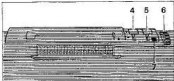
PATTERN PANEL FUNCTION
text_image
4 5 6CARD RELEASE KNOB '4'
If knob is set . . . . . . . . to ●
Punch card is locked and will not feed when carriage is moved across needle bed, also feed dial '6' cannot be turned.
If knob is set . . . . . . . . to ▼
Punch card is free and will turn when carriage is moved across needle bed. Card can also be turned by moving feeding dial '6'.
PATTERN MEMORY INDICATOR '7'
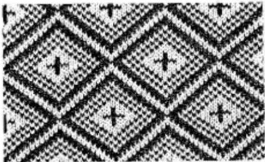
natural_image
Abstract geometric pattern with repeating diamond shapes and plus signs (no text or symbols)Blue colour indicates that next pattern row is memorised in memory drums.
Red colour indicates that previous pattern row will be repeated.
PATTERN VARIATION KNOB '5'
If knob is set . . . . . . . . to S card moves every row and a standard pattern can be knitted.
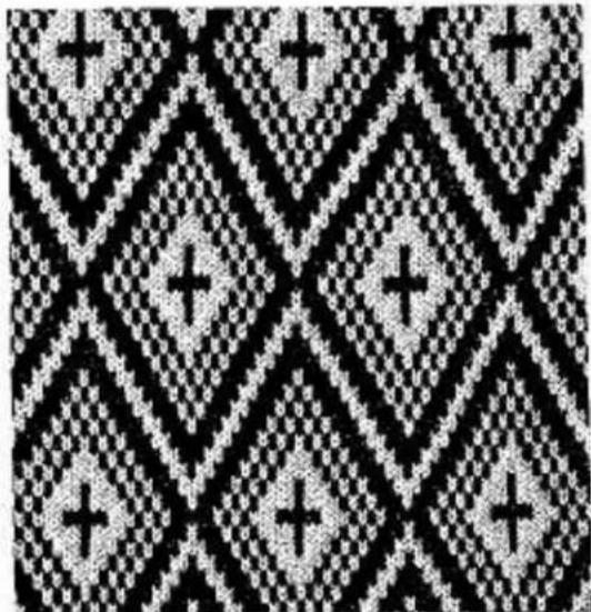
natural_image
Black and white pixelated pattern with repeating diamond shapes and plus signs (no text or symbols)If knob is set . . . . . . . . to L card moves only every second row and expanded patterns can be knitted.
NOTE:
When knitting expanded patterns with pattern variation knob '5' set to 'S', always start first row of pattern knitting from right to left.
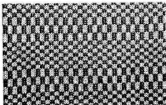
natural_image
Black and white abstract pattern with repeating geometric shapes (no text or symbols)Very interesting patterns can be knitted by simply changing pattern variation knob '5' during pattern knitting.
text_image
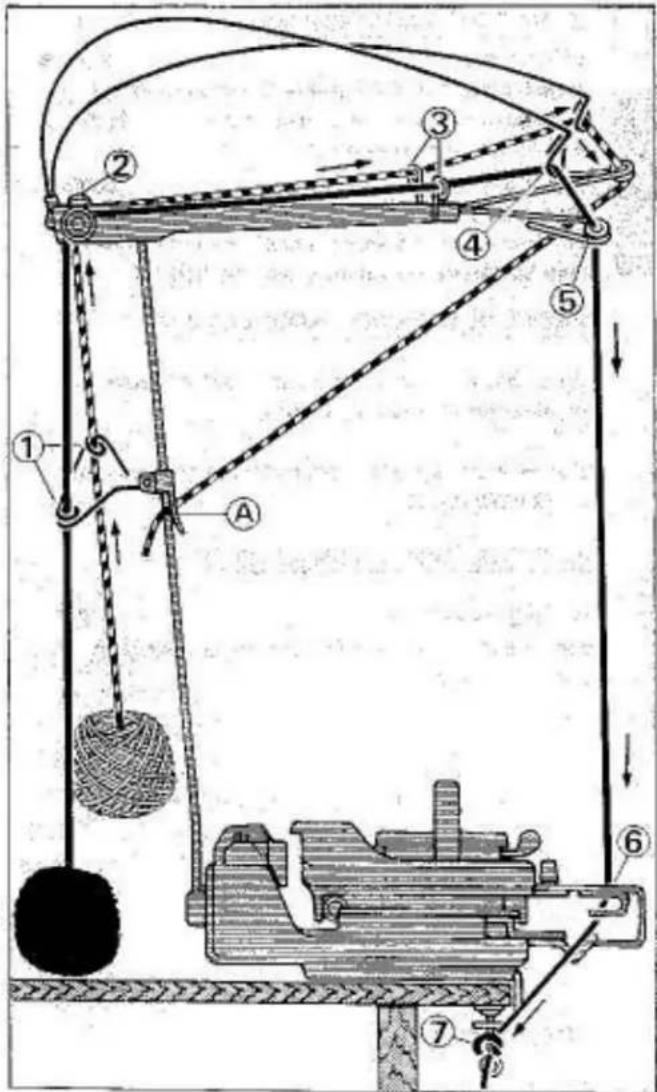
Technical diagram of a mechanical lifting device with numbered components and directional arrows indicating motion or force.Place carriage on right side.
Thread machine with the yarn with which you intend to knit the garment (main yarn) as follows:
- Through yarn guide eyelet.
- Between the two tension discs and underneath stop pin.
-
Through yarn guide eyelet.
-
Through take-up spring eyelet.
-
Through yarn guide eyelet.
-
Into main feeder No. 1 by pushing pin 'A' to
the left and sliding yarn into slot. Close feeder by pushing pin 'A' to the right.
- Fasten yarn end onto right side table clamp.
Thread a second ball of yarn in contrast colour (waste yarn) in the same way as main yarn up to yarn guide eyelet 5.
Pull yarn downwards and hook yarn end into yarn clip 'A' on uprod.
When second colour yarn is required, remove yarn from yarn clip 'A' and thread into feeder as per instructions given.
text_image
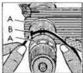
A B AIMPORTANT:
Before continuing check that the yarn is placed BETWEEN discs 'A' and UNDER pin 'B'
Adjust yarn brake tension.
natural_image
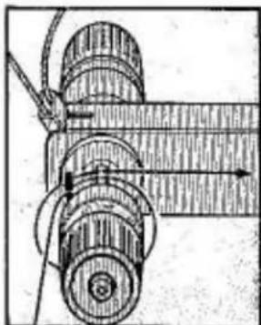
Technical line drawing of a mechanical assembly with rollers and a shaft (no text or symbols)FOR PUNCH LACE you have to use a thin cotton thread same colour as main yarn or a transparent nylon thread.
In order to keep the thread under tension, thread has to be turned once completely around the yarn brake centre pin (See illustration).
Adjust yarn brake tension to No. 5.
NOTE: As many patterns can be knitted in 3 or 4 colours, we recommend you purchase an additional yarn brake complete with uprod which can be easily fitted to your machine.
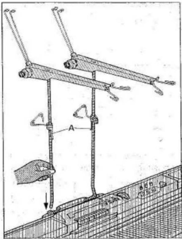
HOW TO ASSEMBLE FOUR YARN BRAKES
text_image
Technical diagram showing mechanical assembly with labeled component 'A' and directional arrow indicating motionRIGHT YARN BRAKE
On the right side of handle, insert short bent end of yarn brake rod with yarn clip 'A' away from you, into bracket socket.
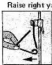
left until it passes the yarn rod and turn it towards the back.
Turn take-up spring upwards and place yarn brake onto yarn brake rod.
LEFT YARN BRAKE
On the left side of handle, insert short bent end of yarn brake rod with yarn clip 'A' facing you, into bracket socket.
Raise rear yarn guide.
Turn take-up spring upwards and place yarn brake onto yarn brake rod.
THREADING OF YARN BRAKE
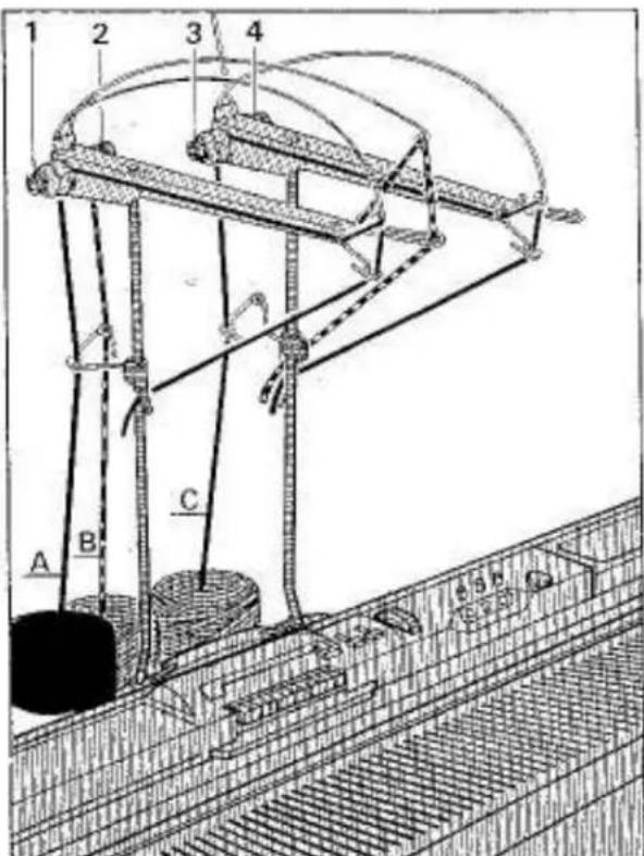
text_image
1 2 3 4 A B C 5 6THREE COLOURS
- Thread MAIN YARN 'A' into yarn brake No. 1 and hook yarn end into left side yarn clip.
- Thread COLOUR 'B' into yarn brake No.2 and hook yarn end into right side yarn clip.
- Thread COLOUR 'C' into yarn brake No.3 and hook yarn end into right side yarn clip.
FOUR COLOURS
Thread COLOUR 'D' into yarn brake No. 4 and hook yarn end into right side yarn clip.
B-6 CARRIAGE SETTING
This column indicates carriage setting. In this instance you would set:
LEFT SIDE LEVER. . . . . . to
LEFT FRONT LEVER. . . . . to
CAMLEVER . . . . . . . . to 0
RIGHT FRONT LEVER . . . . . to
RIGHT SIDE LEVER. . . . . . to
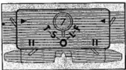
text_image
Diagram showing a device with a numbered component and directional arrows, possibly indicating motion or signal flow.CAM LEVER SETTING
'T' ..... TUCK STITCH
'S' ..... SLIP STITCH
'0' . . . . PLAIN KNITTING
'L' ..... PUNCH LACE
'F' . . . . FAIR ISLE
| MOTIF | TUCKSTITCH | SLIPSTITCH | PLATTING | LACE | PUNCHLACE | FAIRISLE | WEAVING | |||||||||
| SIDE LEVER SETTING | ▶ | ◀ | ▶ | ◀ | ▶ | ◀ | ▶ | ◀ | ▶ | ◀ | ▶ | ◀ | ▶ | ◀ | ▶ | ◀ |
| FRONT LEVER SETTING | I | I | I | I | II | II | I | I | I | I | I | II | II | II | II | II |
| CAM LEVER SETTING | F | T | S | T | T | L | F | O | ||||||||
B-7 FEEDER THREADING
Knitting with one colour only using feeder No. 1
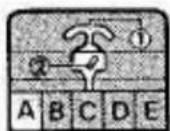
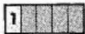
'A' indicates that main yam is only used.
'1' indicates that main yarn must be threaded into feeder No. 1.
B-7 FEEDER THREADING
Knitting with two colours using feeder No. 1 only.
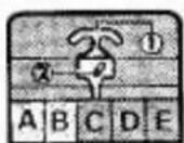
'A' and 'B' indicates that two colours are used.
'1' indicates that yarn in feeder No. 1 must be changed whenever a colour change is necessary.

B-7 FEEDER THREADING
Knitting with more than one colour using feeder No. 1 only.
'A', 'B' and 'C' indicates that three colours are used.
1 indicates that yarn in feeder No.1 must be changed whenever a colour change is necessary.
text_image
Technical diagram showing mechanical assembly with labeled parts and directional arrowsThread yarn brake with main colour.
Open main feeder.
Thread main yam into feeder No. 1.
Fasten yarn end to table clamp.
Close feeder.
natural_image
Diagram of a mechanical or structural component with grid patterns and an arrow indicating direction (no text or symbols)When knitting with more than one colour, lay yarns not used around yarn clip on side of machine.
B-7 FEEDER THREADING
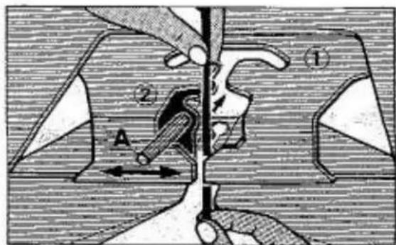
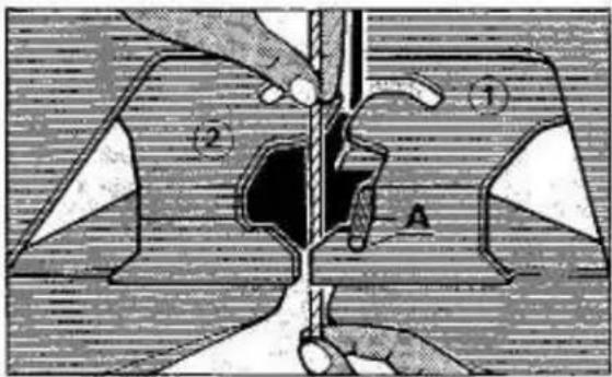
Knitting with more than one colour using feeder No. 1 and 2.
'A' and 'B' indicates that two colours are used.
1 indicates that main yarn must be threaded into main feeder No.1.
2 indicates that second colour must be threaded into feeder No. 2.
text_image
Technical diagram showing mechanical assembly with labeled parts and directional arrows, likely from an engineering or patenting context.a) Thread yarn brake with main yarn.
Open main feeder.
Thread main yarn into feeder No. 1.
Fasten yarn end to table clamp
Close feeder.
Cmplar-Knitmanen. 37
text_image
Technical diagram showing a mechanical assembly with labeled parts and directional arrows, likely illustrating a process or manufacturing procedure.b) Thread yarn brake with second colour yarn. Thread second colour yarn into feeder No.2 to the left side of pin 'A'. Fasten yarn end to table clamp.
NOTE: When knitting punch lace patterns - Thread nylon or cotton thread into feeder No.2 to the left side of pin 'A'. Fasten thread end to table clamp.
natural_image
Technical diagram of a mechanical or structural component with hatched areas and a diagonal line, no visible text or symbols.If you knit with three of more colours, lay yarns not in use around yarn clip on side of machine.
B-7a and B-7b FEEDER THREADING
for PLATTING PATTERN
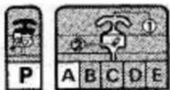
B-7a Triangle (▲) mark indicates that platting yarn must be threaded into feeder No.1 as follows:
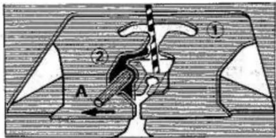
B-7b 'A' indicates that main yarn is threaded into main feeder No. 1.
text_image
Technical diagram showing mechanical assembly with labeled components A and numbered parts 1 and 2a) Thread yarn brake with platting yarn. Move carriage to extreme right. Open main feeder. Thread platting yarn from the top into main feeder No. 1 and pull yarn behind yarn feeder hole 'B'. Fasten yarn end to table clamp.
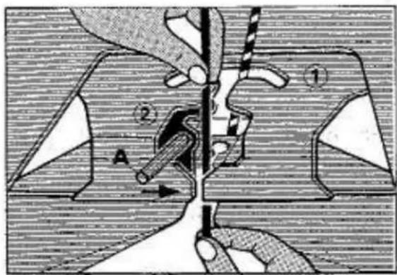
text_image
Technical diagram showing mechanical assembly with labeled parts and directional arrowb) Thread yarn brake with main yarn. Thread main yarn into feeder No. 1. Fasten yarn end to table clamp. Close feeder.
NOTE: If you thread feeder as above - MAIN YARN will be on the right side of fabric. PLATTING YARN will be on the left side of fabric.

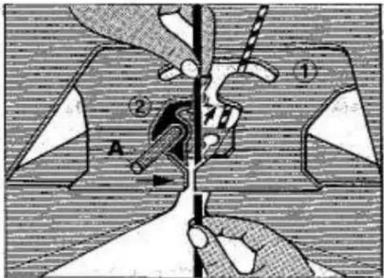
text_image
Technical diagram showing mechanical assembly with labeled parts and directional arrowsIf you prefer to use the platting yarn on the right side of fabric, thread feeder as follows:
a) Thread main yarn from the top into main feeder No. 1 and pull yarn behind yarn feeder hole 'B'. Fasten yarn end to table clamp.
b) Thread platting yarn into feeder No. 1, close feeder by moving pin 'A' to the right and fasten yarn end to table clamp.
B - 7a and B - 7b
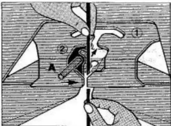
FEEDER THREADING for WEAVING PATTERNS
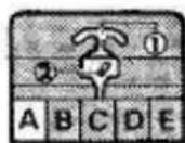


B-7a indicates that main yarn is threaded into main feeder No. 1.
B-7b Triangle (▲) mark indicates that weaving yarn must be threaded as follows:
text_image
Technical diagram showing a mechanical assembly with labeled parts and directional arrows indicating motion or force.Carriage on right side.
Thread yarn brake with main yarn.
Open feeder.
Thread main yam into feeder No. 1.
Fasten yarn end to table clamp.
Close feeder.
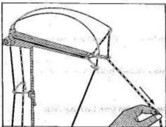
natural_image
Technical line drawing of a mechanical assembly with no visible text or symbolsThread yarn brake with weaving yarn.
Pull yarn downwards towards carriage in front of main yarn and fasten yarn end to table clamp.
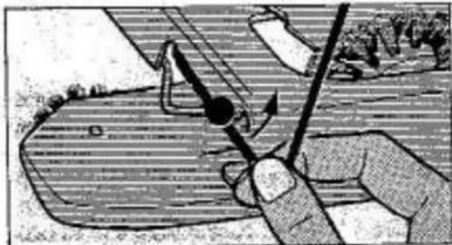
natural_image
Illustration of a hand using a tool to interact with a surface, showing motion arrows (no text or symbols)KNITTING FROM RIGHT TO LEFT
Hook weaving yarn into left side yarn holder.
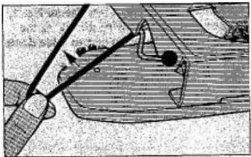
natural_image
Illustration of a hand holding a tool interacting with a mechanical component (no visible text or symbols)KNITTING FROM LEFT TO RIGHT
a) Remove weaving yarn from left yarn holder by moving same backwards and underneath of sinker arm.
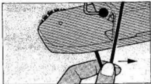
natural_image
Illustration of a hand holding a bird's head with a pen inserted, showing no text or symbolsb) Move weaving yarn to the right side of sinker arm.
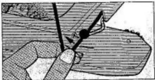
natural_image
Illustration of a hand using a tool to cut or mark a surface, no text or symbols presentc) Hook weaving yarn into right side yarn holder.
B-8 KNITTING INSTRUCTIONS
R
'R' column indicates knitting procedure.
1
Single arrow pointing to the right indicates to knit from left to right.
B
Double arrow pointing to left and right indicates to knit as many rows as required.
2 2
Arrow on side of card indicates repeat operation from 1 as many times as required.
NEEDLE ARRANGEMENT and FRONT LEVER SETTING for PLAIN KNITTING
| NEEDLE ARRANGEMENT | FRONT LEVERS TO | WEAVING | FAIR ISLE | SLIP STITCH | PUNCH LACE | TUCK STITCH | TUCK PLATTING | |
| 1 Needle on carriage side to 'D' position | II | II | ● | ● | ||||
| 1 Needle opposite carriage to 'D' position | II | II | ● | |||||
| 1 Needle left and right side to 'D' position. | II | II | ● | |||||
| 2 Needles opposite carriage to 'D' position | II | II | ● | ● | ||||
WEAVING PATTERN

natural_image
Simple line drawing of a lamp with a bulb on top and a light bulb on the side, no text or symbols present.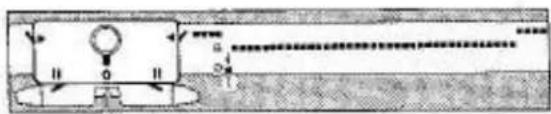
natural_image
Pure electrical circuit lines without any symbolsCARRIAGE SETTING:
Cam lever to 0
Front lever to ll
Side lever to
IMPORTANT:
For correct pattern knitting it is necessary to bring the last needle knitted on carriage side from 'B' to 'D' position after every row knitted.
FAIR ISLE PATTERN
text_image
Diagram showing a mechanical or electrical component with labeled parts and directional arrows, likely illustrating a motion or force system.
text_image
Diagram showing a mechanical or optical setup with labeled components and directional arrows, likely illustrating a physical or engineering concept.CARRIAGE SETTING:
Cam lever to F
Front lever to II
Side lever to
IMPORTANT:
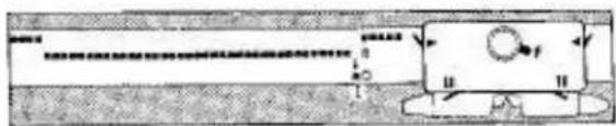
For correct pattern knitting it is necessary to bring the last needle knitted on carriage side from 'B' to 'D' position after every row knitted.
SLIP STITCH PATTERN
text_image
Diagram showing a mechanical or structural system with labeled components and directional arrows, likely illustrating a process or motion.CARRIAGE SETTING:
Cam lever to S
Front lever to H
Side lever to
natural_image
Pure mechanical diagram showing a rectangular block with internal components and arrows, no text or symbols present.IMPORTANT:
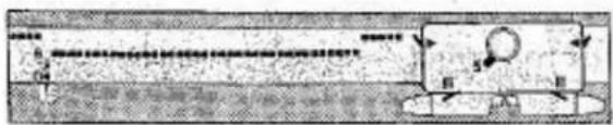
At the beginning of every row, bring last needle knitted on the opposite side of carriage from 'B' to 'D' position.
PUNCH LACE PATTERN

text_image
Diagram showing a rectangular object with labeled dimensions and a magnifying glass, likely illustrating a physical or engineering concept.CARRIAGE SETTING:
Cam lever to L.
Front lever to II
Side lever to
IMPORTANT:
a) Always start to knit from right to left.
b) Before starting to knit bring last needle knitted on left and right side of fabric from 'B' to 'D' position.
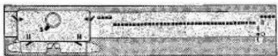
c) KNIT 2 ROWS.
Repeat operation (b) and (c).
TUCK STITCH PATTERN and TUCK STITCH PLATTING PATTERN
text_image
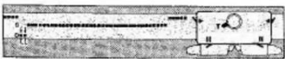
0 1 2 3 4 5 6 7 8 9 10 11 12 13 14 15 16 17 18 19 20 21 22 23 24 25 26 27 28 29 30 31 32 33 34 35 36 37 38 39 40 41 42 43 44 45 46 47 48 49 50 51 52 53 54 55 56 57 58 59 60 61 62 63 64 65 66 67 68 69 70 71 72 73 74 75 76 77 78 79 80 81 82 83 84 85 86 87 88 89 90 91 92 93 94 95 96 97 98 99 100CARRIAGE SETTING:
Cam lever to T
Front lever to ll
Side lever to
text_image
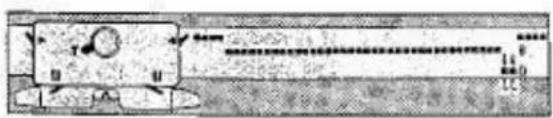
Diagram showing a mechanical or electrical component with labeled sections and directional arrows, likely illustrating a motion or force system.IMPORTANT:
We recommend at the beginning of every row you bring the last 2 needles on the opposite side of carriage from 'B' to 'D' position in order that the end stitches are correctly knitted.
NEEDLE ARRANGEMENT and FRONT LEVER SETTING for PARTIAL KNITTING
| NEEDLE ARRANGEMENT | FRONT LEVERS TO | WEAVING | FAIR ISLE | SLIP STITCH | PUNCH LACE | TUCK STITCH | TUCK PLATTING | |
| 1 Needle on carriage side to 'C' position. | I | I | ● | ● | ||||
| 1 Needle opposite carriage to 'C' position | I | I | ● | |||||
| 1 Needle left and right side to 'C' position | I | I | ● | |||||
| 2 Needles opposite carriage to 'C' position | I | I | ● | ● | ||||
WEAVING PATTERN
natural_image
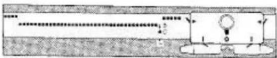
Simple line drawing of a mechanical component with no text or symbolsCARRIAGE SETTING:
Cam lever to 0
Front lever to
Side lever to
natural_image
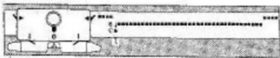
Pure electrical circuit lines without any symbolsIMPORTANT:
For correct pattern knitting it is necessary to bring the last needle knitted on carriage side from 'B' to 'C' position after every row knitted.
FAIR ISLE PATTERN
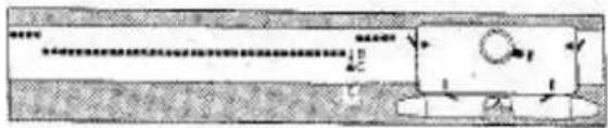
natural_image
Pure mechanical diagram showing a shaft and base with no text, numbers, or symbolsCARRIAGE SETTING:
Cam lever to F
Front lever to
Side lever to
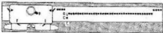
text_image
Technical diagram with labeled components and directional arrows, likely from an engineering or mechanical drawing.IMPORTANT:
For correct pattern knitting it is necessary to bring the last needle knitted on carriage side from 'B' to 'C' position after every row knitted,
SLIP STITCH PATTERN
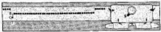
text_image
Diagram showing a mechanical or electrical component with labeled parts and directional arrows indicating motion or flow.CARRIAGE SETTING: Cam lever to S
Front lever to I
Side lever to
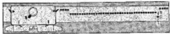
text_image
Diagram showing a mechanical or structural component with labeled parts and directional arrows indicating motion or force.IMPORTANT: At the beginning of every row bring last needle knitted on opposite side of carriage to 'C' position.
PUNCH LACE PATTERN

text_image
Diagram showing a mechanical or optical setup with labeled components and directional arrows, possibly illustrating a motion or signal flow.CARRIAGE SETTING: Cam lever to L
Front lever to I
Side lever to
IMPORTANT: a) Always start to knit from right to left.
b) Bring last needle knitted on left and right side of fabric to 'C' position.
c) Knit 2 rows (right to left, left to right).
Repeat operation (b) and (c).
TUCK STITCH PATTERN and TUCK STITCH PLATTING PATTERN
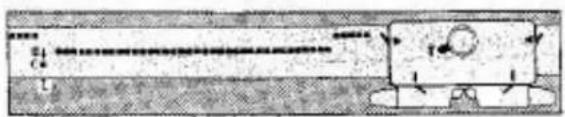
text_image
Technical diagram showing a mechanical component with labeled parts and directional arrows indicating motion or force.CARRIAGE SETTING: Cam lever to T
Front lever to I
Side lever to
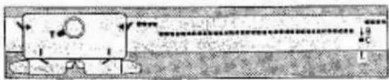
natural_image
Pure mechanical component diagram without any text, numbers, or symbolsIMPORTANT: We recommend at the beginning of every row you bring last 2 needles on the opposite side of carriage to 'C' position in order that the end stitches are correctly knitted.
HOW TO READ THE PATTERN CARDS
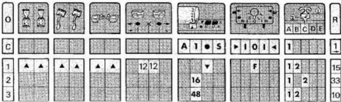
MOTIF KNITTING
| A-5 (24-58) | Empirical-Kuitmaster |
text_image
Grid-based puzzle or game board layout with numbered panels and icons, likely for a logic or logic simulation.USE PUNCH CARD NO. A-5
OPERATION - C
Stop with carriage on left side of fabric.
Insert punch card No. 5 side 'A' into pattern panel slot.
Set the No.-1 above the triangle (▲) mark.
Set card release knob . . . . . . . . . . to ●
Set pattern variation knob. . . . . . . . to S
Set carriage left side lever . . . . . . . . to ▶
Set carriage left front lever . . . . . . . . to
Set carriage cam lever . . . . . . . . . . to 0
Set carriage right front lever . . . . . . . to
Set carriage right side lever . . . . . . . . to
Thread main yarn into feeder No. - 1.
KNIT ONE ROW from left to right.
OPERATION - 1
Attach claw weights to fabric.
Place the yarn separator fingers under the empty needles.
Attach the magic cams to the carriage.
Place black line of left point cam between the 12th and 13th needle on the left from the centre of (X) mark.
Place white line of right point cam between the 12th and 13th needle on the right from the centre of (X) mark.
Set card release knob . . . . . . . . . . to ▼
Set cam lever . . . . . . . . . . . . . to F
Thread colour 'B' into yam feeder No. - 2.
KNIT 15 ROWS.
OPERATION - 2 No. 16 on punch card must be above the triangle (▲) mark.
Remove colour 'B' from yarn feeder No. - 2 and thread colour 'C' into yarn feeder No. - 2.
KNIT 33 ROWS.
OPERATION - 3 No. 48 on punch card must be above the triangle (▲) mark.
Remove colour 'C' from yarn feeder No. - 2 and thread colour 'B' into yarn feeder No. - 2.
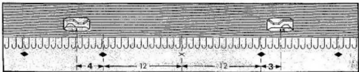
NOTE: When using Card No. 19-03, the point cams are placed differently in operation 1. See illustration below.
text_image
4 12 12 3Left point cam 4 needles to the left of
Right point cam 3 needles to the right of
(◆) mark.
(◆) mark.
TUCK STITCH PATTERN

text_image
Empisal-Knitmaster® 8 0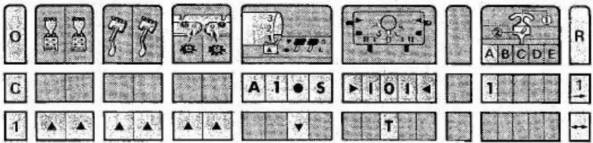
text_image
Cropped image of a grid-based puzzle or logic board layout with labeled buttons and icons, likely from a game or educational material.USE ANY ONE OF THE PUNCH CARDS SHOWN IN THE PATTERN BOOK
OPERATION - C Stop with carriage on left side of fabric.
Insert punch card side 'A' into pattern panel slot.
Set the No. - 1 above the triangle (▲) mark.
Set card release knob to ●
Set pattern variation knob. . . . . . . . to S
Set carriage left side lever . . . . . . . . to ▶
Set carriage left front lever . . . . . . . to I
Set carriage cam lever . . . . . . . . . . to0
Set carriage right front lever . . . . . . . . to
Set carriage right side lever . . . . . . . . to
Thread main yarn 'A' into yarn feeder No. - 1.
KNIT ONE ROW from left to right.
OPERATION - 1 Attach claw weights to fabric.
Place the yarn separator fingers under the empty needles.
Attach the round brushes to the sinker plate.
Set card release knob to ▼
Set carriage cam lever . . . . . . . . . . to T
KNIT AS MANY ROWS AS REQUIRED.

PLATTING PATTERN

text_image
Empirical-Knitmaster® B 0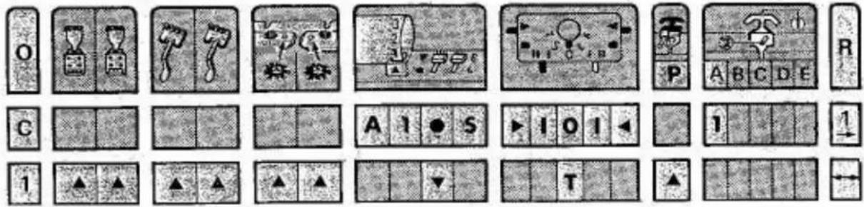
text_image
Cropped image of a grid-based puzzle or game interface with icons, numbers, and symbols, likely from a game or simulation tool.USE PUNCH CARD NO. 11-A or 12-A
OPERATION - C
Stop with carriage on left side of fabric.
Insert punch card side 'A' into pattern panel slot.
Set the No. · 1 above the triangle (▲) mark.
Set card release knob . . . . . . . . . . to ●
Set pattern variation knob. . . . . . . . to S
Set carriage left side lever . . . . . . . . . to
Set carriage left front lever . . . . . . . . to
Set carriage cam lever . . . . . . . . . . to 0
Set carriage right front lever . . . . . . . to
Set carriage right side lever . . . . . . . . to
Thread main yarn 'A' into yarn feeder No. - 1.
KNIT ONE ROW from left to right.
OPERATION - 1
Attach claw weights to fabric.
Place the yarn separator fingers under the empty needles.
Attach the round brushes to the sinker plate.
Set card release knob to ▼
Set carriage cam lever . . . . . . . . . to T
Thread platting yarn behind feeder No. - 1.
KNIT AS MANY ROWS AS REQUIRED.
WEAVING PATTERN
| Empisal-Knitmaster® | B— |
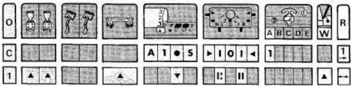
USE PUNCH CARD NO. -1A FOR PRACTICE
OPERATION - C Stop with carriage on left side of fabric.
Insert punch card side 'A' into pattern panel slot.
Set the No. - 1 above the triangle (▲) mark.
Set card release knob . . . . . . . . . . to ●
Set pattern variation knob. . . . . . . . to 5
Set carriage left side lever . . . . . . . . to ▶
Set carriage left front lever . . . . . . . to
Set carriage cam lever . . . . . . . . . . to0
Set carriage right front lever . . . . . . . . to
Set carriage right side lever . . . . . . . . to
Thread main yarn 'A' into yarn feeder No. - 1.
KNIT ONE ROW from left to right.
OPERATION - 1 Attach claw weights to fabric.
Attach weaving brushes to the carriage.
Set card release knob . . . . . . . . . . to▼
Set carriage left and right side levers . . . . . to ||
Thread weaving yarn.
KNIT AS MANY ROWS AS REQUIRED.
HELPFUL HINTS
natural_image
Illustration of a woman operating an old typewriter (no text or symbols visible)CASTING-ON PROBLEMS:
When you cast-on it is always best to cast-on with a very loose tension, i.e. from 7 upwards.
This gives you a large loop between the gate and the needle hook and when you lay your nylon thread across these loops, it is easy for you to pull the thread well down below the needle hooks thus enabling the hooks to pass OVER THE NYLON THREAD of your next row.
If the first row of stitches is too tight or if you do not pull the nylon thread well down, then when you knit your next row the needles will incorrectly pass UNDER THE NYLON THREAD causing it to be 'knitted in' thereby either jamming your carriage or spoiling your cast-on. In this case you will have to restart the casting-on.
STITCHES ARE NOT KNITTED ON THE SIDE:
If you return the carriage BEFORE IT HAS PASSED THE LAST NEEDLES IN 'B' POSITION BY SEVERAL CM., it can happen that the first stitches of the row are not knitted and sometimes it may happen that a complete row is not knitted. In the case that stitches are not knitted, unravel this row and re-start it again - also set the row counter back. If a complete row is not knitted, slide the carriage completely off the needle bed and re-start from the other side - also set the row counter back.
DROPPED STITCHES ON THE SIDE:
Dropped stitches will occur on the sides of your knitting if your yarn brake is not properly threaded and your take-up spring is not automatically taking up all slack yarn between the feeder mouth and the needles. Loose loops may also form on the sides.
Dropped stitches or loose loops may occur at the sides of your knitting if you move your carriage too far past the knitting after knitting a row - then too much yarn is pulled from the yarn brake and you have slack yarn between the carriage and the knitting.
This is easily avoided if you just pull back any slack yarn behind the yarn brake.
DROPPED STITCHES IN THE CENTRE:
Can be caused by:
- too loose or too tight a tension
- a tension unsuitable for the pattern
— yarn is not suitable for the pattern
Inside your sinker arm are two rectangular black brushes. As you move your carriage, these brushes brush open and hold open your needle latches so that your yarn feeder can lay yarn into the hooks as the carriage passes the needles.
If these brushes are badly worn, or if the sinker arm has not been placed into the carriage properly, then the brushes cannot serve their function and dropped stitches will result. Dropped stitches are easy to repair.
DROPPED STITCHES:
These can be caused by a knot in the yarn or by yarn which has been badly or too tightly wound, thus preventing the smooth flow of yarn from the ball to the knitting.
HOW TO REPAIR A DROPPED STITCH:
Once you are accustomed to machine knitting, you will very seldom drop a stitch.
But as soon as you notice a dropped stitch, you should repair it. So, let's try —
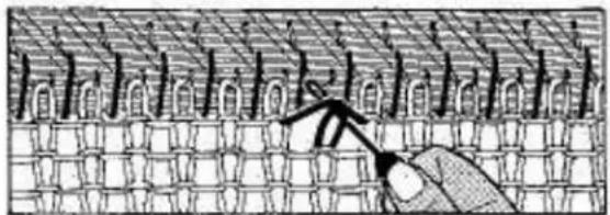
natural_image
Diagram of a hand using a tool to interact with a grid-patterned surface (no text or symbols)Insert the transfer tool inside the dropped stitch.
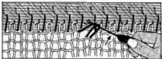
natural_image
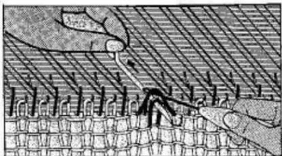
Diagram showing a hand interacting with a grid-like pattern, possibly depicting a mechanical or electrical component (no text or symbols present)Hook the transfer tool into the empty needles. Lift the loose bar of yarn and the stitch onto the empty needle.
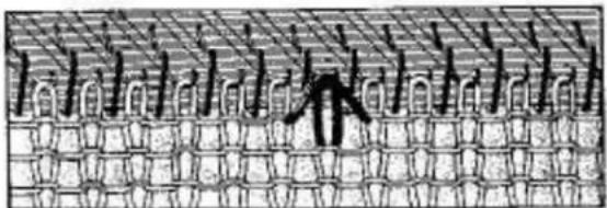
natural_image
Diagram of a plant cell with visible chromosomes and stomata (no text or labels)There is now 1 stitch and 1 bar on the empty needle.
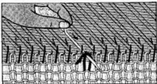
natural_image
Diagram showing a hand inserting into a microarray with arrows indicating process (no text or symbols)First, push the needle up to 'D' position, then pull the needle slightly back - just until the bar and the stitch are behind the latch - then STOP.
natural_image
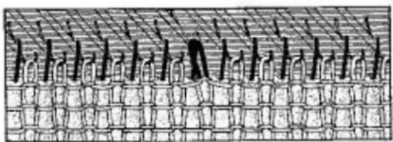
Illustration of hands using a tool to interact with a textured surface, no text or symbols presentLift the loose bar of yarn over the latch INTO the hook and leave the stitch BEHIND the latch.

natural_image
Illustration of a hand using a tool to cut or mark a patterned surface with no visible text or symbolsPull the needle back down towards 'B' position thus pulling the bar of yarn through the stitch.
natural_image
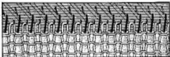
Diagram of a grid-patterned structure with vertical supports and horizontal lines, no text or symbols presentPush the needle further back towards 'A' position to enable it to form a bigger stitch.
natural_image
Cross-sectional diagram of a layered structure with vertical supports and rectangular elements (no text or labels)Pull your knitting down and sideways until gradually the newly repaired stitch assumes the same shape as all other stitches.
REPAIRING A LADDER OF DROPPED STITCHES
text_image
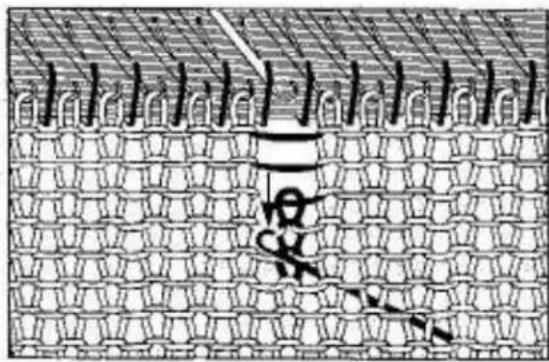
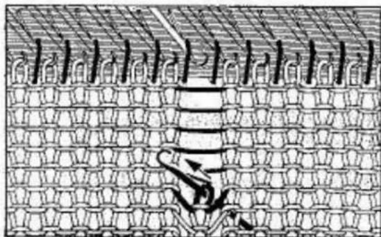
Cropped image showing a grid pattern with faint vertical lines and handwritten or printed symbols, possibly from a technical or educational material.Insert the latchet hook from behind your knitting through a stitch a few rows below the dropped stitch.
Undo stitches down to the latchet hook by pulling down on the latchet hook.
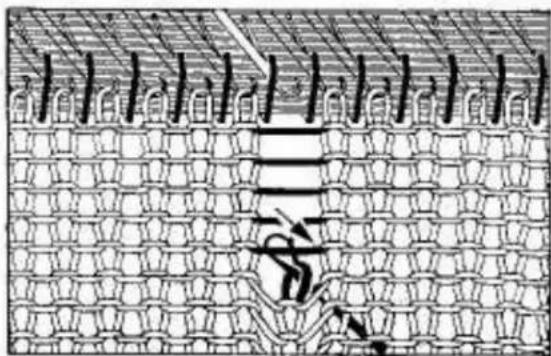
natural_image
Diagram of a grid-patterned structure with no visible text or symbolsPush the latchet hook towards you so that the stitch comes behind the latch, and the hook catches the cross thread.
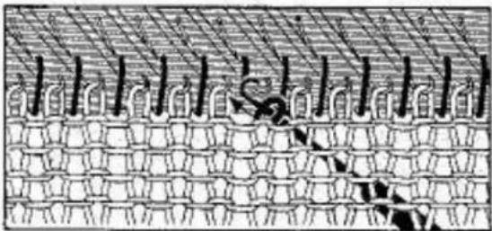
text_image
Diagram showing a grid structure with labeled components and Chinese characters, possibly illustrating a technical or mathematical concept.Draw back the latchet hook. The cross thread is trapped in the closed latch. Pull the cross thread through the loop thus forming a knitted stitch.
natural_image
Diagram of a layered structure with repeating patterns and no visible text or symbolsPush the latchet hook towards you again until the stitch is BEHIND the latch. Catch the next cross thread in the hook and pull it through the stitch. Repeat until you reach the top.

natural_image
Diagram of a mechanical or structural assembly with repeating components and a tool interacting with a central component (no text or symbols present)Pull the last stitch rather tight to make a bigger loop. Insert transfer tool into this loop from the front. Carefully remove this stitch from the latchet hook and place it on the needle with your transfer tool.
UNDOING ROWS - UNRAVELLING
Unravelling is quick and very simple to do and may save quite a considerable amount of time.
IT MAY BE NECESSARY TO UNRAVEL —
If you have knitted too many rows.
If you have made a mistake in your knitting or pattern.
If your carriage jams and it is necessary to release the carriage and re-start the row where the fault occurred.
If you have one or more dropped stitches in the middle of a row, it is much easier to unravel 2 or 3 rows and then just lift the dropped stitches back onto their respective needles.
YOU CAN ONLY UNRAVEL WHEN ALL YOUR STITCHES ARE INSIDE THE NEEDLE HOOKS.
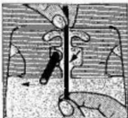
natural_image
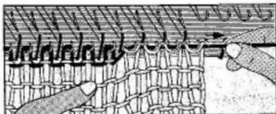
Illustration of a hand holding a tool interacting with a mechanical component (no text or symbols visible)TO UNRAVEL 4 ROWS PROCEED AS FOLLOWS:
Remove the yarn from the yarn feeder.
natural_image
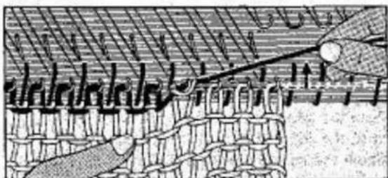
Diagram of a woven textile or mesh structure with diagonal striped patterns and two hands interacting (no text or symbols)Hold the knitting down with your left hand and with your right hand pull the yarn sideways, as illustrated.
natural_image
Cross-sectional diagram of a geological or biological structure with layered textures and directional arrows (no text or symbols)Lift the yarn upwards and very slightly backwards and you will notice that the stitches of the previous row automatically slide back into the needle hooks.
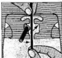
Repeat pulling the yarn and lifting the stitches of the previous row into the needle hooks until you have unravelled 4 rows.
When unravelling from the LEFT, you must pull the thread towards the LEFT.
natural_image
Illustration of a hand holding a tool interacting with a vertical object, no text or symbols present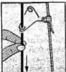
natural_image
Diagram of a rope being lifted by a hook, showing rope movement and force direction (no text or labels)Thread yarn back into the yarn feeder.
Pull back all the loose yarn behind the yarn brake.
DO NOT FORGET TO SET BACK THE ROW COUNTER FOR THE NUMBER OF ROWS UNRAVELLED.

HOW TO RESET ROW COUNTER, PUNCH CARD AND CARRIAGE
AFTER UNRAVELLING
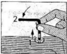
text_image
Diagram showing a hand holding a tool with labeled parts 1 and 2, indicating a process or step in a procedure.a) Disengage row counter tripper.
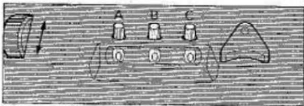
text_image
A B C 1b) Turn row counter numbers back as many rows as unravelled.
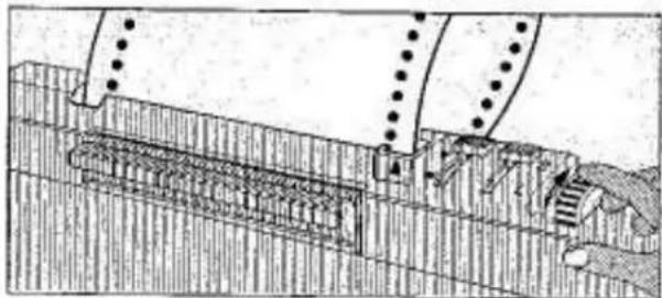
natural_image
Technical line drawing of a mechanical assembly or structural component (no visible text or symbols)c) Turn punch card back as many times as rows unravelled.
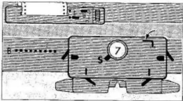
text_image
Technical diagram of a mechanical device with labeled parts and motion indicatorsd) To memorise pattern in memory drums:
Set card release knob to ●
Set pattern variation knob. . . . to S
Set both side levers . . . . . . to ■
Set cam lever . . . . . . . to S
Set both front levers . . . . . to I
Ensure that needles are in 'B' position and proceed as follows:
natural_image
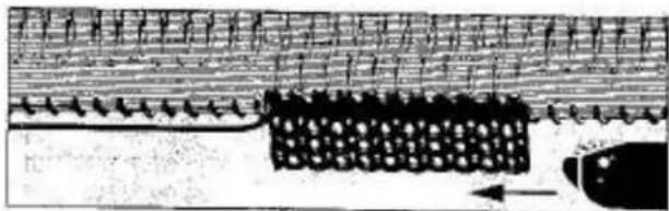
Diagram of a microfluidic device with layered channels and a central granular structure (no text or symbols)e) If yarn end is on opposite side of carriage move carriage only once across the needle bed.
natural_image
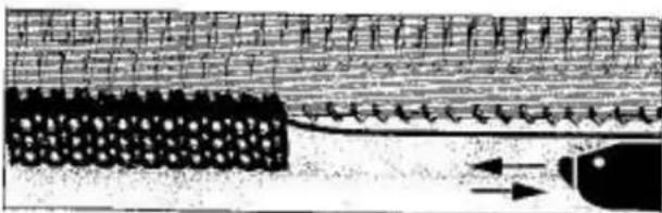
Diagram of a mechanical or structural component with layered structure and directional arrows (no text or symbols)f) If yarn end is on same side as carriage move carriage twice across the needle bed.
text_image
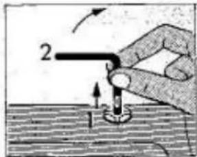
Diagram showing a hand holding a tool with labeled parts and directional arrows indicating motion or movement.g) Engage row counter tripper.
text_image
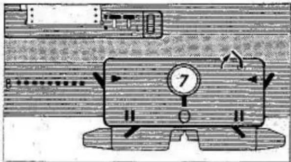
Technical diagram showing a mechanical device with labeled components and directional arrows indicating motion or movement.h) Set card release knob . . . . . to▼
Set pattern variation knob in accordance with pattern instructions.
Set carriage side levers, front levers and cam lever in accordance with pattern instructions.
Continue to knit.
natural_image
Technical line drawing of a mechanical assembly or device with no visible text or symbolsNOTE: If pattern variation knob is set to 'L' during pattern knitting and you have to unravel rows, preset the punch card as follows:
| PATTERN MEMORY INDICATOR RED | |
| ROWSUNRAVELLED | TURN PUNCHCARD BACK BY |
| 1 | 1 ROW |
| 2 | 1 ROW |
| 3 | 2 ROWS |
| 4 | 2 ROWS |
| 5 | 3 ROWS |
| 6 | 3 ROWS |
| 7 | 4 ROWS |
| PATTERN MEMORY INDICATOR BLUE | |
| ROWSUNRAVELLED | TURN PUNCHCARD BACK BY |
| 1 | NONE |
| 2 | 1 ROW |
| 3 | 1 ROW |
| 4 | 2 ROWS |
| 5 | 2 ROWS |
| 6 | 3 ROWS |
| 7 | 3 ROWS |
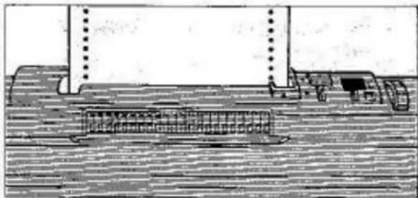
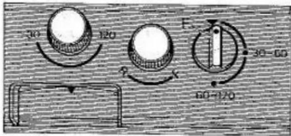
HOW TO RESET KNITRADAR AFTER UNRAVELLING
text_image
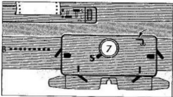
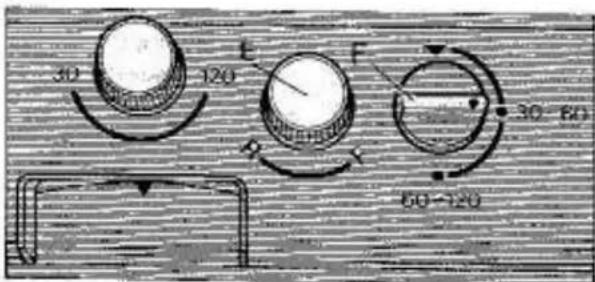
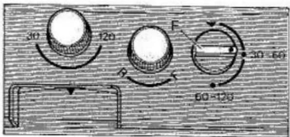
30 120 F 30-60 60-120Set row setting dial 'F' to ▼ Unravel required rows.
text_image
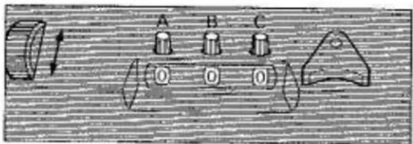
A B C O O ODisengage row counter tripper. Turn row counter numbers as many rows as unravelled.
natural_image
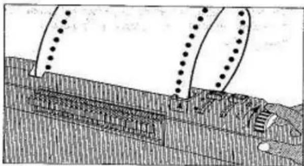
Technical line drawing of a mechanical assembly with rollers and structural supports (no text or symbols)Turn punch card back as many rows as unravelled.
text_image
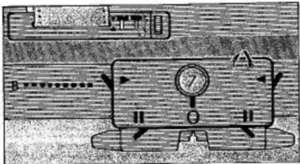
Technical diagram showing a mechanical device with labeled parts and numbered componentsTo memorise pattern in memory drums:
Set card release knob . . . . . . to ●
Set pattern variation knob. . . . . to S
Set both side levers . . . . . . . to
Set cam lever . . . . . . . . . to S
Set both front levers . . . . . . to I
Ensure needles are in 'B' position.
Move carriage once or twice across the needle bed and stop on side of yarn end.
text_image
30 120 60-120 30 60Set row setting dial 'F' to original setting.
Turn back pattern graph as many rows as unravelled by simply turning paper feed knob 'E' in 'R' direction.
text_image
Diagram of a mechanical device with labeled components and directional arrows indicating motion or movement.Engage row counter tripper.
Set card release knob . . . . . . to▼
Set pattern variation knob in accordance with pattern instructions.
Set carriage side levers, front levers and cam lever in accordance with pattern instructions.
Continue to knit.
IF YARN IS ENTANGLED IN THE MEMORY DRUMS
natural_image
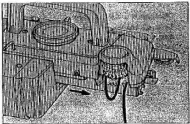
Technical line drawing of a mechanical assembly with no visible text or symbolsWhile knitting ensure that the rear of the carriage is clear of yarn.
It may happen that accidentally the yarn does become entangled inside the memory drums.
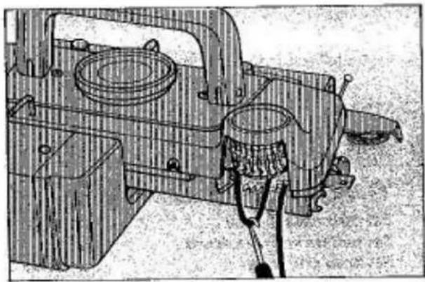
To remove yarn, move carriage halfway across the needle bed to free the jammed memory drums.
natural_image
Technical line drawing of a mechanical device with internal components and mounting brackets (no text or symbols)Carefully remove yarn using the latchet tool.
NOTE: Do not use force as this will damage the drums.
If this happens during pattern knitting proceed as per instructions on Page 59.
IF CARRIAGE IS ACCIDENTALLY REMOVED FROM MACHINE
natural_image
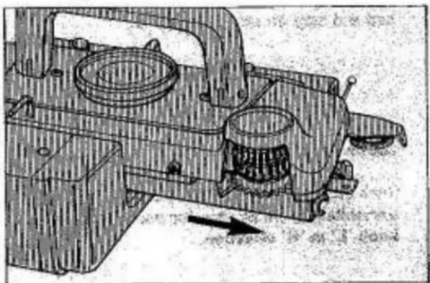
Technical line drawing of a mechanical assembly with no visible text or symbolsIf carriage is accidentally removed from machine during pattern knitting, proceed as per instructions on Page 59.
text_image
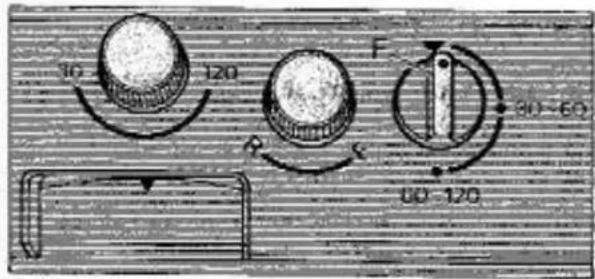
10 120 R F 30-60 60-120Set row setting dial 'F' . . . . . . to ▼
text_image
Technical diagram showing a mechanical device with labeled parts and directional arrows, likely illustrating a motion or assembly process.Disengage row counter tripper.
To memorise pattern in memory drums:
Set card release knob . . . . . . to ●
Set pattern variation knob. . . . . to S
Set both side levers . . . . . . to
Set cam lever . . . . . . . . . to S
Set both front levers . . . . . . to I
Ensure needles are in 'B' position.
Move carriage once or twice across the needle bed and stop on side of yarn end.
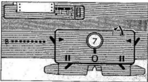
text_image
30 120 60-120Set row setting dial to original setting.
text_image
Diagram of a mechanical device with labeled components and directional arrows indicating motion or movement.Engage row counter tripper.
Set card release knob . . . . . . to ▼
Set pattern variation knob in accordance with pattern instructions.
Set carriage side levers, front levers and cam lever in accordance with pattern instructions.
Continue to knit.
IF THE CARRIAGE JAMS
SOMETIMES THE CARRIAGE MAY JAM IN THE MIDDLE OF A ROW. IF THIS HAPPENS IT IS NOT SERIOUS, AND NO CAUSE FOR WORRY. DO NOT FORCE OR HIT THE CARRIAGE TO GET IT LOOSE —
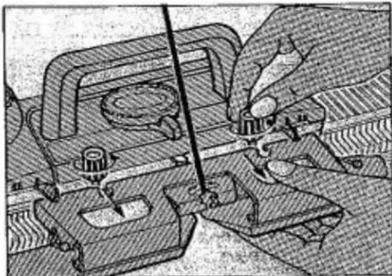
natural_image
Technical illustration of a mechanical assembly with hands operating a tool (no visible text or symbols)PROCEED AS FOLLOWS:
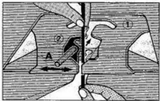
Set the row counter out of action. Loosen the two knurled nuts which secure the sinker arm assembly to the carriage. Pull the sinker arm towards you OFF the carriage. If necessary, cut the yarn to separate the sinker arm from the carriage. Take care that there are no needle hooks caught in the yarn feeder.
You can now easily lift up the carriage from the front of the needle bed and it will still be held by the guide rail at the back of the needle bed.
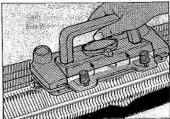
natural_image
Technical illustration of a mechanical assembly with no visible text or symbolsHold the carriage up in its raised position and move it across the needle bed away from the knitting in the direction from which it came.
Replace the carriage onto the needle bed.
Remove the yarn from the yarn feeder. Check that there is no yarn twisted around the brushes below the sinker arm assembly. If there is, clear it and replace the sinker arm assembly back onto the carriage.
Set the row counter back into action. Unravel the last row. If the last row has been counted, set the row counter back. Rethread the yarn.
THE CARRIAGE IS HEAVY TO MOVE IF -
-
The yarn is wound too tightly and does not flow easily into the needles.
The yarn you are using is too hard or too heavy.
The yarn is unsuitable for use on your machine.
The yarn is not suitable for the pattern which you are knitting. -
The tension is either too loose or too tight.
-
Your machine is dirty or needs oiling.
-
The yarn brake has been incorrectly threaded.
-
The yarn was tangled in the yarn brake during knitting.
HOW TO CHANGE A NEEDLE
text_image
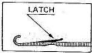
LATCHNeedle with damaged latches will cause faulty knitting or dropped stitches and therefore need to be changed.
The needle latch must move easily and lie flat over the needle hook.
natural_image
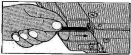
Illustration of a hand holding a pen, with mechanical components and arrows indicating motion (no text or symbols)At each side of the needle bed you can see the needle retaining bar.
If the damaged needle is at the right half of the centre - push the raised end of the copper plate into the needle bed at the right.
natural_image
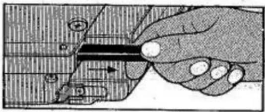
Hand holding a tool with a ruler, showing mechanical components (no text or symbols visible)The needle retaining bar is then pushed out of the needle bed at the left and you can pull it out of the needle bed until the damaged needle lies free.
natural_image
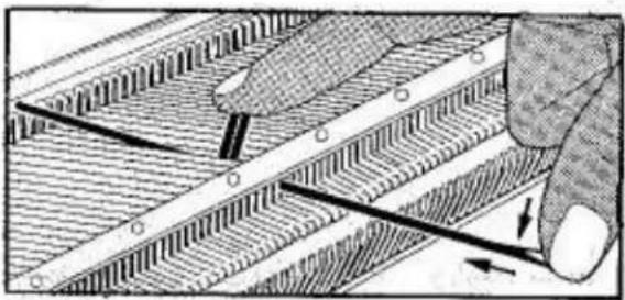
Illustration of a hand using a tool to interact with a circuit board (no text or symbols visible)Push the damaged needle by the butt up to 'D' position. With your thumb push the needle hook down as shown, unless the needle is badly worn, the heel will lift out of the needle bed. If not, use the work hook - slide it inside the needle bed from the top and bring the shank of the needle below the opening of the needle bed to let it come out. Hold the heel of the damaged needle and pull it backwards out of the needle bed.
natural_image
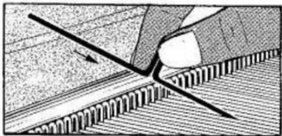
Diagram showing a hand holding a tool interacting with a textured surface, possibly depicting a mechanical or structural component (no text or symbols present)Open the latch of the new needle and slide it into the groove of the needle bed as shown by the arrow - the needle must come to 'D' position - then let the shank slide into the needle bed, move the needle back to 'A' position.
text_image
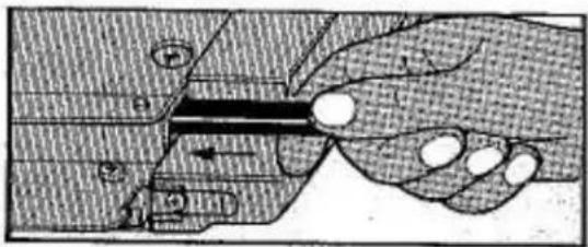
Technical diagram showing a hand holding a tool with labeled components and directional arrows, likely illustrating a mechanical or electrical process.Check that the needle slides smoothly in the needle bed from 'A' to 'D' position.
Insert the needle retaining bar back inside the needle bed as shown.
MAINTENANCE OF THE MACHINE
natural_image
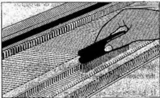
Illustration of a hand using a tool to interact with a textured surface (no text or symbols visible)To clean the machine - remove the carriage from the needle bed completely.
Bring all needles up to 'D' position and with the little brush remove all lint from the needle number plate.
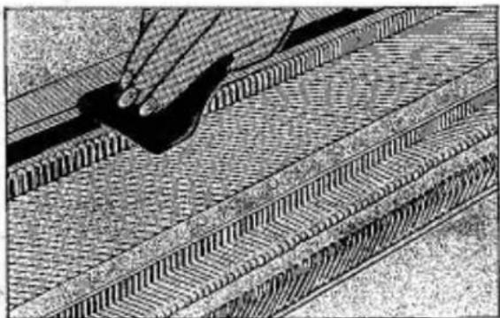
natural_image
Close-up of a hand using a tool to cut or mark a patterned surface with diagonal lines (no text or symbols visible)Remove any lint that may be around the brushes below the sinker arm assembly.
With a paper tissue or a soft dry cloth remove oil from guide rail of machine and from below the carriage.
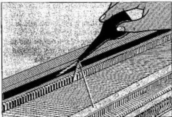
natural_image
Illustration of a hand using a tool to inspect or repair a textured surface, no text or symbols visibleWhen starting to knit - slide the oil bottle along the guide rail of the machine, the needle butts and the front guide of the needle bed.

natural_image
Cross-sectional diagram of a mechanical assembly (no visible text or labels)The red marking shows you where the parts below the carriage need oiling before knitting.
Oil lightly.
HOW TO REPACK THE MACHINE
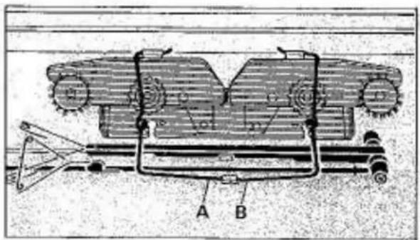
text_image
Technical diagram of a mechanical device with labeled parts A and B, showing internal components and assembly structure.Remove yarn brake and sinker arm assembly from machine and pack into machine lid.
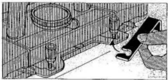
natural_image
Technical line drawing of a mechanical assembly with no visible text or symbolsSecure carriage to machine with lock plate.
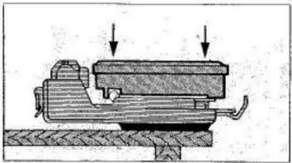
natural_image
Mechanical assembly diagram showing a piston and housing with two downward arrows indicating force or movement (no text or labels present)Pack accessories into accessory box and place accessory box onto the left side of needle bed.
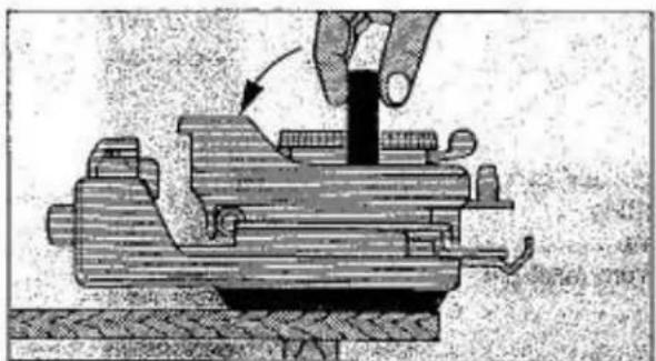
natural_image
Mechanical assembly diagram showing a hand operating a workpiece with a rotating shaft (no text or symbols)Lower carriage handle.
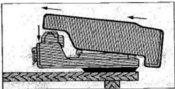
natural_image
Mechanical assembly diagram showing a clamping mechanism with directional arrows indicating motion (no text or labels)Place machine lid onto needle bed.
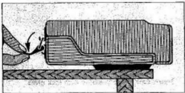
natural_image
Diagram of a mechanical assembly with a tool interacting with a component, no visible text or symbolsLock both latches on the back of the machine.
Store machine in a dry place.
INDEX
CAST-ON :
15
CARRIAGE SETTINGS FOR PATTERNS
36
EXPLANATION OF ACCESSORIES
Claw weights 24
Magic Cam 26
Punch Card and Pattern Panel 31
Pattern Panel Function . . . . . . . . . . . . . . . . . . 33
Point Cam 27
Round Brushes 29
Weaving Brush Assembly 30
Yam Separator Fingers. 24
HELPFUL HINTS
Casting-on problems.
Stitches are not knitted on the side.
Dropped Stitches.
Dropped Stitches on the side
Dropped Stitches in the centre
How to repair Dropped Stitches
Unravelling.
How to reset row counter, punch card and carriage after unravelling
How to reset Knitradar after unravelling . . . . . . . .
Yarn entangled in the memory drums . . . . . . . . .
If carriage is accidentally removed from machine . . . . . .
If carriage jams . . . . . . . . . . . . . . . . .
If carriage is heavy to move
How to change a needle
HOW STITCHES ARE FORMED
9
HOW TO READ THE PATTERN CARD
for Motif Knitting 45
for Tuck Stitch Patterns 47
for Platting. 48
for Weaving 49
MACHINE
Unpacking
Setting up
Main Parts
Threading 12
Maintenance
Repacking
NEEDLE ARRANGEMENT AND FRONT LEVER SETTING
for Plain Knitting. 41-42
for Partial Knitting 43-44
43-44
PATTERN CARDS 22
Explanation 23-40
PUNCH CARD 21
REMOVING KNITTING FROM MACHINE WITHOUT CASTING OFF
TENSION AND STITCH SIZE 14
THREADING THE MACHINE 12
For Fair Isle or Lace. 37
For Plating 38
For Weaving 39
YARN BRAKE
Setting up 5
Threading for 1 colour . . . . . . . . . . . . . . . . . . . . . . . . . . . . . . . . . . . . . . . . . . . . . . . . . . . . . . . . 12
Threading for 2 colours. 34
Threading for 3 and 4 colours 35
YARN PREPARATION 11
41-42
22
23 - 40
21
18 14 12 37 38 39
5 12 34 35 11