
BRC 545610 - Termostat IMIT - Gratis brugsanvisning og manual
Find enhedens vejledning gratis BRC 545610 IMIT i PDF-format.

Brugerspørgsmål om BRC 545610 IMIT
0 spørgsmål om dette apparat. Besvar dem du kender, eller stil dit eget.
Stil et nyt spørgsmål om dette apparat
Download vejledningen til din Termostat i PDF-format gratis! Find din vejledning BRC 545610 - IMIT og tag din elektroniske enhed tilbage i hånden. På denne side er alle dokumenter nødvendige for brugen af din enhed offentliggjort. BRC 545610 af mærket IMIT.
BRUGSANVISNING BRC 545610 IMIT

text_image
Manuale istruzioni- Instructions manual Notice technique -Bedienungsanleitung. Handleiding - Manual de instrucciones Manual de instruções - Однүүөс Хрөгөөөс Instrukcje obsługi - РУКОВОДСТВО ПО ЭКСПИРАТАЦИИ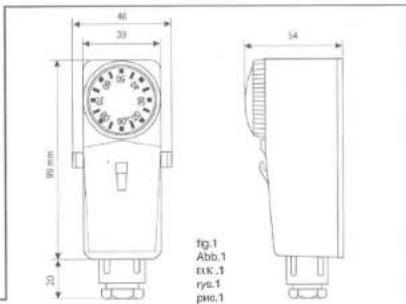
text_image
46 33 99 mm 70 54 fig.1 Abb.1 euk.1 yrs.1 pnc.1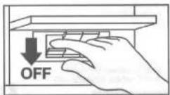
fig.2 - Abb.2 - EIK.2 - rys.2 - pnc.2
natural_image
Mechanical device with a dial indicator and mechanical components, no visible text or symbolsfig.3 - Abb.3 - шк .3 - гус.3 - рис.3
natural_image
Mechanical component with a cylindrical shaft and mounting bracket, shown against a vertical background (no text or symbols)fig.4 - Abb.4 - cik.4 - rys.4 - pnc.4
fig.5 - Abb.5 - p1K.5 - rys.5 - pwc.5
text_image
fig.6 - Abb.6 - кв.к.б - рус.б - рис.б B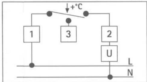
flowchart
graph TD
    A["1"] --> B["+"]
    C["2"] --> D["U"]
    E["3"] --> F["+"]
    G["4"] --> H["+"]
    I["5"] --> J["+"]
    K["6"] --> L["+"]
    M["7"] --> N["+"]
    O["8"] --> P["+"]
    Q["9"] --> R["+"]
    S["10"] --> T["+"]
    U["11"] --> V["+"]
    W["12"] --> X["+"]
    Y["13"] --> Z["+"]
    AA["14"] --> AB["+"]
    AC["15"] --> AD["+"]
    AE["16"] --> AF["+"]
    AG["17"] --> AH["+"]
    AI["18"] --> AJ["+"]
    AK["19"] --> AL["+"]
    AM["20"] --> AN["+"]
    AO["21"] --> AP["+"]
    AQ["22"] --> AR["+"]
    AS["23"] --> AT["+"]
    AU["24"] --> AV["+"]
    AW["25"] --> AX["+"]
    AY["1"] --> Z
    AZ["2"] --> AA
    BA["3"] --> BB
    BC["4"] --> BC
    BD["5"] --> BE
    BF["6"] --> BG
    BH["7"] --> BI
    BJ["8"] --> BK
    BL["9"] --> BM
    BN["10"] --> BO
    BP["11"] --> BP
    BQ["12"] --> BR
    BS["13"] --> BT
    BU["14"] --> BV
    BW["15"] --> BX
    BY["16"] --> BZ
    CA["17"] --> CB
    CC["18"] --> CB
    DD["19"] --> DB
    DB --> DC
    DV["20"] --> DW
    DX["N"] --> DX
INTRODUCTION

Thank you for your confidence in our Company and for choosing one of our products.
This bimetallic contact THERMOSTAT is particularly suitable for temperature measurements on heating systems pipes.
CONFORMITY TO THE STANDARDS
CONFORMITY TO THE GUIDELINES
This product complies with:
This product complies with:
- EN 60/30-1 and subsequent
- B.T. 73/23/EEC
EN 60730-2-9
and later updating of 93/68/EEC
TECHNICAL DATA
These data refer to tests performed on ∅60 mm pipes
TEMPERATURE RANGE = 20°÷90°C
TEMPERATURE DIFFERENTIAL = 8±3 DEGREE OF PROTECTION. ID 20
DEGREE OF PROTECTION = IP 30 INSULATION CLASS - I
INSULATION CLASS = 1 TEMPERATURE RATE OF CHANGE — \~1K/min
TEMPERATURE RATE OF CHANGE = 10.9mm MAXIMUM HEAD TEMPERATURE = 90°C
MAXIMUM HEAD TEMPERATURE = 60°C STORAGE TEMPERATURE = -15°\~60°C
OUTPUT = cutoff or switching contacts
CONTACTS RATING = 1-2 = 16(2.5)A/250V\~ 1-3 = 2.5A/250V\~
SWITCH ACTION = 18
POLLUTION DEGREE =
FAIRLEAD TYPE = M20×1.5
MOUNTING = on pipe
FOR THE ELECTRIC CONNECTIONS USE CABLES: 1≤90°C cable H05 V2V2-F
T>90°C cable N2GMH2G-J/0
INSTALLATION AND CONNECTIONS

SAFETY INSTRUCTIONS
Before connecting the thermostat, make sure that the power supply voltage of the UNIT TO BE CONTROLLED (boiler, pump, etc.) IS NOT CONNECTED and that it matches the indication given inside the appliance. (Fig.2)
Make also sure that the unit suits the thermostat contacts rating features (see paragraph "Technical Data").
INSTALLATION
WARNING:
All the installation operations included in this manual, must be carried out by qualified personnel only, strictly complying with all safety and law provisions in force.
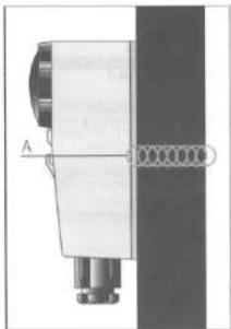
A) Fix the appliance to the pipe by means of its specific fastener. (fig.3)
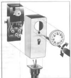
B) Disjoint the adjusting knob (when present) and then release the relevant fixing screw. Remove the front cover. Thread the power supply wires in the provided fairlead and connect them to the appliance terminals (fig.4) according to the instructions of the following paragraph "Wiring Connections". Snap the front cover back, tighten it by means of the provided screw and then fit the knob in its proper seat (if applicable).
A = Spring-band
WIRING CONNECTIONS
CONNECTIONS
fig.5
Terminal 1 = Common contact
Terminal 2 = It opens the circuit when temperature raises
Terminal 3 = It closes the circuit when the temperature raises
Normally (heating plants) use terminals 1 and 2.
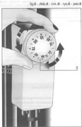
TEMPERATURE SETTING
See fig.6
B - Temperature adjusting knob