
SM-3R40 - Accessoires vélo SHIMANO - Gratis brugsanvisning og manual
Find enhedens vejledning gratis SM-3R40 SHIMANO i PDF-format.

Brugerspørgsmål om SM-3R40 SHIMANO
0 spørgsmål om dette apparat. Besvar dem du kender, eller stil dit eget.
Stil et nyt spørgsmål om dette apparat
Download vejledningen til din Accessoires vélo i PDF-format gratis! Find din vejledning SM-3R40 - SHIMANO og tag din elektroniske enhed tilbage i hånden. På denne side er alle dokumenter nødvendige for brugen af din enhed offentliggjort. SM-3R40 af mærket SHIMANO.
BRUGSANVISNING SM-3R40 SHIMANO
SI-0123A-001-00
Important Safety Information
WARNING
- When installing components, be sure to follow the instructions that are given in the instruction manuals. It is recommended that you use only genuine Shimano parts. If parts such as bolts and nuts become loose or damaged, the bicycle may suddenly fall over, which may cause serious injury.
In addition, if adjustments are not carried out correctly, problems may occur, and the bicycle may suddenly fall over, which may cause serious injury.
• After reading the instruction manual thoroughly, keep it in a safe place for later reference.
- If you have any questions, consult a dealer or an agency.
CAUTION
- Be sure to shift the lever one gear at a time, and reduce the force being applied to the pedals during shifting. If you try to force operation of the shifting lever while the pedals are being turned strongly, your feet may come off the pedals and the bicycle may topple over, which could result in serious injury.
- Never place your foot on the bell crank. Otherwise, gear shifting may not function properly.
Note:
For maximum performance we highly recommend Shimano lubricants and maintenance products. Products are not guaranteed against natural wear and deterioration from normal use and aging.
SI-0123A-001
REVOSHIFT Lever/ Bell Crank 4 /Bell Crank 6 (For internal 3-speed hubs)
Instructions for use
Be sure to read these technical service instructions in conjunction with the technical service instructions for the Inter-3 hub.
REVOSHIFT lever operation
Turn the REVOSHIFT lever to shift one gear at a time.
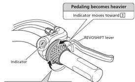
Pedaling becomes lighter
Indicator moves toward 1
I..... Starting/Riding on sandy or rough road surfaces/Riding up slopes/Carrying heavy loads/Riding into headwinds
2......Riding on flat road surfaces
3......Riding at high speeds
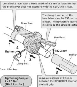
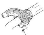
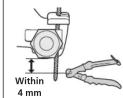
Installation of the lever
nstall the lever as shown in the illustration.
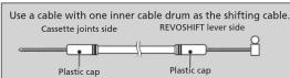
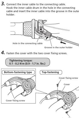
Installation of the shifting cable
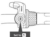
1. Set the REVOSHIFT lever to ①
VOSHIFT lever side
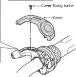
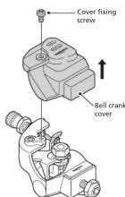
- Loosen the two cover fixing screws, and then remove the cover.
Cover fixing screw
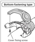
Top-fastening type
Note:
The cover is fastened from the top or bottom, depending on the type being used.
Check the specifications and remove the cover accordingly.
Note:
The cover is fastened from the top or bottom, depending on the type being used.
Check the specifications and attach the cover accordingly.
Bull crank side
- Loosen the cover fixing screw, and then remove the bell crank cover.
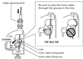
- Loosen the inner cable fixing nut on the main bell crank unit. Next, pass the inner cable from the cable adjusting bolt along the groove in the link and then in between the link and the inner cable fixing plate.
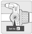
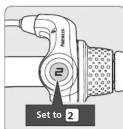
- Set the REVOSHIFT lever to 2
Next, pull the inner cable so that the edges of the link on the main bell crank unit are between the two yellow lines on the window, and then tighten the inner cable fixing nut at that position.
Tightening torque: 4 - 6 N·m {35 - 52 in. lbs.}
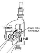
After tightening the inner cable fixing nut, cut off any excess inner cable.
- Replace the bell crank cover and tighten the cover fixing screw.
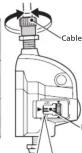
Installation of bell crank
- Insert the push rod into the hub axle.
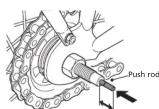
Approx. 14 mm
The end of the push rod should project from the end of the hub axle by approximately 14 mm.
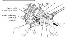
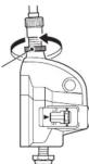
- While pushing the main bell crank unit onto the hub axle, align the serrations inside the main bell crank unit with the hub nut, and then push the main bell crank unit on until it touches the end of the hub axle. In this position, tighten the main unit installation bolt onto the hub axle.
Tightening torque: 3 - 5 N·m (27 - 43 in. lbs.)
Adjusting bell crank
- Set the REVOSHIFT lever to 2
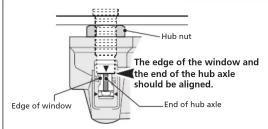
Next, turn the cable adjusting bolt until the red line on the push rod is aligned with the end of the hub axle.
rod and the end of the hub axle
The red line on the push rod and the end of the hub axle should be aligned.


Yellow line
— Yellow line
— Yellow line
Red line on push rod SET Yellow section of link
If the red line on the push rod is not visible, adjust so that the yellow section of the link is between the two yellow lines on the window.

Note:
Look at the two yellow lines
from directly above during
adjustment.
- While turning the crank arm, move the REVOSHIFT lever from 3 to 1 and then from 1 back to 3 two or three times to check the gear shifting.
Set the REVOSHIFT lever back to ② and check that the red line on the push rod is aligned with the end of the hub axle.
If they are not aligned, turn the cable adjusting bolt to make fine adjustments.
- After adjusting the
bell crank, tighten the
cable adjusting nut to secure the cable
adjusting bolt.
Tightening torque: 1.5 - 2.5 N·m {14 - 21 in. lbs.}
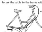
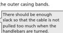
Securing the shifting cable to the frame
* Service Instructions in further languages are available at:
SHIMANO
SHIMANO AMERICAN CORPORATION
One Holland, Irvine, California 92618, U.S.A. Phone: +1-949-951-5003
SHIMANO EUROPE B.V.
Industrieweg 24, 6071 C1 Nunspeet, The Netherlands Phone. +31-341-272222 SUMANO INC
3-77 Oimatsu-cho, Sakai-ku, Sakai-shi, Osaka 590-8577, Japan
Please note: Specifications are subject to change for improvement without
© Apr. 2014 by Shimano Inc.
2.4.10.2017, 2018 and the
- SI-0123A-001-00
- Important Safety Information
- WARNING
- CAUTION
- Note:
- REVOSHIFT Lever/ Bell Crank 4 /Bell Crank 6 (For internal 3-speed hubs)
- Instructions for use
- REVOSHIFT lever operation
- Installation of the lever
- VOSHIFT lever side
- Bull crank side
- Installation of bell crank
- Adjusting bell crank
- Securing the shifting cable to the frame
- SHIMANO
Mærke : SHIMANO
Model : SM-3R40
Kategori : Accessoires vélo