
SL-4603 - Accessoires vélo SHIMANO - Gratis brugsanvisning og manual
Find enhedens vejledning gratis SL-4603 SHIMANO i PDF-format.

Brugerspørgsmål om SL-4603 SHIMANO
0 spørgsmål om dette apparat. Besvar dem du kender, eller stil dit eget.
Stil et nyt spørgsmål om dette apparat
Download vejledningen til din Accessoires vélo i PDF-format gratis! Find din vejledning SL-4603 - SHIMANO og tag din elektroniske enhed tilbage i hånden. På denne side er alle dokumenter nødvendige for brugen af din enhed offentliggjort. SL-4603 af mærket SHIMANO.
BRUGSANVISNING SL-4603 SHIMANO
SI-6UR0A-001-00
General Safety Information
WARNING
- Obtain and read the service instructions carefully prior to installing the parts. Loose, worn or damaged parts may cause the bicycle to fall over and serious injury.
Loose, worn of damaged parts may cause the bicycle to fall over and serious injury may occur as a result. We strongly recommend only using genuine Shimano
replacement parts.
- Obtain and read the service instructions carefully prior to installing the parts. If adjustments are not carried out correctly, the chain may come off and this may
cause you to fall off the bicycle which could result in serious injury.
- Read these Technical Service Instructions carefully, and keep them in a safe place for later reference.
for later reference
Note
- For smooth operation, use the specified outer casing and bottom bracket cable
guide.
- Grease the inner cable and the inside of the outer casing before use to ensure that they slide properly.
- Use a frame with internal cable routing is strongly discouraged as it has tendencies to improve the SIC shifting function due to its high cable resistance.
• Operation of the levers related to gear shifting should be made only when the front
chainwheel is turning. • Use an outer casing which still has some length to spare even when the
handlebars are turned all the way to both sides. Furthermore, check that the
shifting lever does not touch the bicycle frame when the handlebars are turned all
• A special grease is used for the gear shifting cable. Do not use DURA-ACE grease
or other types of grease, otherwise they may cause deterioration in gear shifting performance.
• Do not disassemble the indicator and shifting lever unit, as this may damage them
or cause mis-operation.
- Parts are not guaranteed against natural wear or deterioration resulting from
Parts are not guaranteed against natural wear of deterioration resulting from normal use.
- For maximum performance we highly recommend Shimano lubricants and
maintenance products.
- For any questions regarding methods of installation, adjustment, maintenance or operation, please contact a professional bicycle dealer.
Technical Service Instructions SI-6UR0A-001
SL-R780 / SL-R783
SL-4600 / SL-4603
Shifting lever
In order to realize the best performance, we recommend that the following combination be used.
| Shifting lever | Front | SL-R780 SL-4600 | |
| Rear | |||
| Outer casing | OT-SP41 | ||
| Gears | 20 | ||
| Front derailleur | FD-6700 / FD-5700 FD-4600 | ||
| Front chainwheel | FC-6700 / FC-6750FC-5700 / FC-5750 | FC-4600 / FC-4650 | |
| Rear derailleur | RD-6700 / RD-5700 | RD-4600 | |
| Freehub | FH-6700 / FH-5700 | FH-4600 | |
| Cassette sprocket | CS-6700 / CS-5700 | CS-4600 | |
| Chain | CN-6701/ CN-5701 | CN-4601 | |
| Bottom bracket cable guide | SM-SP17 | ||
| Shifting lever | Front | SL-R783 SL-4693 | |
| Rear | SL-R780 SL-4690 | ||
| Outer casing | OT-SP41 | ||
| Gears | 30 | ||
| Front derailleur | FD-6703 / FD-5703 FD-4603 | ||
| Front chainwheel | FC-6703 / FC-5703 | FC-4603 | |
| Rear deraililleur | RD-6700 / RD-5700 | RD-4600 | |
| Freehub | FH-6700 / FH-5700 | FH-4600 | |
| Cassette sprocket | CS-6700 / CS-5700 | CS-4600 | |
| Chain | CN-6600 / CN-5600 | CN-5600 | |
| Bottom bracket cable guide | SM-SP17 | ||
SHIMANO
SUSILK AMERICAN CORPORATION
SHIMANO AMERICAN CORPORATION One Holland, Irvine, California 92618, U.S.A. Phone: +1-949-951-5003
SOMANS EUROPE &
SHIMANO INC.
SINMANO EUROPE D.V. Industrieweg 24, 8071 CT Nur
3-77 Qimat
* Service Instructions in further language are available at
• Service instructions in further languages are available at http://techdocs.shimano.com
Please note: specifications are subject to change
© Mar. 2011 by Shimano Inc. XBC SZK Printed in Japan.
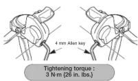
Mounting the shifting lever
Use a handlebar grip with a maximum outer diameter of 32 mm (SL-R780) / 36 mm (SL-4600).
• Install the shifting lever in a position where it will not obstruct brake operation and gear shifting operation.
- Do not use in a combination which causes brake operation to be obstructed.
Note:
When installing the components to carbon frame/handle bar surfaces, verify with the manufacturer of the carbon frame/parts for their recommendation on tightening torque in order to prevent over tightening that can cause damage to the carbon material and/or under tightening that can cause lack of fixing strength for the components.
< Rear >> Front
Gear shifting operation
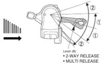
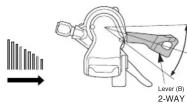
This release lever is equipped with a 2-way release mechanism which allows release operations to be carried out by either pushing or pulling the lever. Both lever (A) and lever (B) always return to the initial position when they are released after shifting. When operating one of the levers, always be sure to turn the crank arm at the same time.
• Front • Back
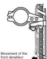
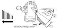
To shift from a small chainring to a larger chainring (Lever A)
When lever (A) is pressed once.
there is a shift of one step from
a small chainring to a larger
chainring.
Example:
from intermediate
chainring to largest
chainring.
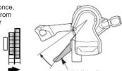
Driver (A) Initial position
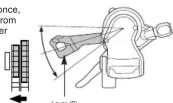
To shift from a large chainring to a smaller chainring (Lever B)
When lever (B) is pressed once.
there is a shift of one step from
a large chainring to a smaller
chainring.
Example:
Example: from largest choosing to
from largest chaining to intermediate chaining.
2-WAY RELEASE
When lever (B) is operated, there is one click where trimming (the noise prevention mechanism) engages, and a second stronger click when the gear shift stroke is completed. After trimming, the next push will complete the gear shift stroke.
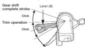
Trimming (noise prevention operation)
If the chain is on the large front chainwheel and the larger rear sprocket, the chain will rub in the front derailleur plate.
producing a characteristic noise. When this happens, press
lever (B) lightly (to the point where it clicks); this causes the first devillow to move slightly.
front derailleur to move slightly towards the smaller chainwheel
towards the smaller chainwheel thereby eliminating the noise.

This service instruction explains how to use and maintain the Shimano bicycle parts which have been used on your new bicycle. For any questions regarding your bicycle or other matters which are not related to Shimano parts, please contact the place of purchase or the bicycle manufacturer.
The levers are equipped with a multi release function which lets you shift two gears with a single release operation. (SL-R780 only)
To shift from a small sprocket to a larger sprocket (Lever A)
You can vary the lever stroke to shift the desired number of gears, so that to shift by one gear only, move the lever to the (1) position, and to shift by two gears at one time, move the lever to the (2) position. A maximum two-gear shift can be made in this manner.
To shift from a large sprocket to a smaller sprocket (Lever B)
You can vary the lever stroke to shift the desired number of gears, so that to shift by one gear only, move the lever to the (1) position, and to shift by two gears at one time, move the lever to the (2) position. A maximum two-gear shift can be made in this manner.
< SL-4600 >
Press lever (B) once to shift one step from a larger to a smaller sprocket.
Installing the shifting cable
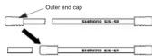
Cutting the outer casing
When cutting the outer casing, cut the opposite end to the end with the marking. After cutting the outer casing, make the end round so that the inside of the hole has a uniform diameter.

Attach the same outer end cap to the cut end of the outer casing.
Installing the inner cable
- Operate lever B 9 times or more to set it to the highest position.
(For the front: Operate lever B 2 times or more to set it to the lowest
position. - Check that the indicator needle is at the left edge.
(For the front: Check that the needle is at the right edge.) - Remove the inner hole cover and install the cable.
* The illustration shows the rear lever.
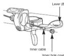

install the inner hole cover by turning it as shown in the illustration until it stops.
Do not turn it any further than this, otherwise it may damage the screw thread.
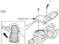
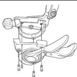
Replacement and assembly of the indicator unit
Disassembly and reassembly should only be carried out when the indicator unit is being replaced.
* The illustration shows the rear lever.
Indicator fixing screws
< Disassembly >
1. Remove the two indicator fixing screws.
2. Turn the indicator unit in the clockwise direction as shown in the illustration, and then lift it up to remove it.
(For the front: Turn it counterclockwise.)
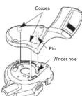
1. Operate lever B 9 times or more to set it to the highest position.
(For the front: Operate lever B 2 times or more to set it to the lowest position.)
2. Check that the indicator needle is at the left edge.
(For the front: Check that the needle is at the right edge.)
3. Insert the pin at the bottom of the indicator into the hole in the winder unit and then insert the indicator unit so that the two bosses are aligned with the marks on the shifting lever unit.
4. Turn the indicator unit counterclockwise as shown in the illustration to install it. (For the front: Turn it clockwise.)
5. Secure the indicator unit by tightening the two indicator fixing screws.
Tightening torque:
0.14 N·m {1.2 in. lbs.}
- Check the operation. If the indicator unit does not operate correctly, reassemble while paying particular attention to steps 1, 2 and 3.

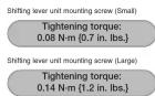
Replacement of the shifting lever unit
Disassembly and reassembly should only be carried out when replacing the shifting lever unit.
- Loosen the cable fixing bolt (nut) of the front derailleur or rear derailleur, and then pull the inner cable out of the shifting lever unit in the same way as when installing the inner cable.
- Remove the indicator unit by following the disassembly procedure given in "Replacement and assembly of the indicator unit".
- Remove the four shifting lever unit mounting screws, and then remove the shifting lever unit as shown in the illustration.
- Align the shifting lever unit and the bracket, and then secure with the four shifting lever unit mounting screws.
- Install the indicator unit by following the assembly procedure given in "Replacement and assembly of the indicator unit".
Mærke : SHIMANO
Model : SL-4603
Kategori : Accessoires vélo