
PLC-8800N - Vidéo-projecteur SANYO - Gratis brugsanvisning og manual
Find enhedens vejledning gratis PLC-8800N SANYO i PDF-format.

Brugerspørgsmål om PLC-8800N SANYO
0 spørgsmål om dette apparat. Besvar dem du kender, eller stil dit eget.
Stil et nyt spørgsmål om dette apparat
Download vejledningen til din Vidéo-projecteur i PDF-format gratis! Find din vejledning PLC-8800N - SANYO og tag din elektroniske enhed tilbage i hånden. På denne side er alle dokumenter nødvendige for brugen af din enhed offentliggjort. PLC-8800N af mærket SANYO.
BRUGSANVISNING PLC-8800N SANYO
SANYO
Multimedia Projector
MODEL PLC-8800N
natural_image
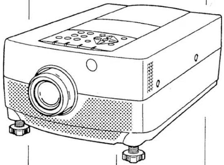
Line drawing of a projector with lens and base mount (no text or symbols)Owner's Manual
INFORMATION TO THE USER
NOTE: This equipment has been tested and found to comply with the limits for a Class A digital device, pursuant to Part 15 of the FCC Rules. These limits are designed to provide reasonable protection against harmful interference when the equipment is operated in a commercial environment. This equipment generates, uses, and can radiate radio frequency energy and, if not installed and used in accordance with the instruction manual, may cause harmful interference to radio communications. Operation of this equipment in a residential area is likely to cause harmful interference in which case the user will be required to correct the interference at his own expense.
TO THE OWNER
As the owner of a new Multi-media Projector, you are probably eager to try out your new projector. Before you do, we suggest that you spend a little time reading this manual to familiarize yourself with the operating procedures, so that you will receive maximum satisfaction from the many features included on your new projector.
This owner's manual will acquaint you with your projector's features. Reading it will help us too. Through the years, we have found that many service requests were not caused by problems with our projectors. They were caused by problems that could have been prevented, if the owner had followed the instructions in the manual.
You can often correct operating problems yourself. If your projector fails to work properly, see "TROUBLESHOOTING" section on pages 49 \~ 50 and try the solutions marked for each problem.
SAFETY PRECAUTIONS
WARNING:
TO REDUCE THE RISK OF FIRE OR ELECTRIC SHOCK, DO NOT EXPOSE THIS APPLIANCE TO RAIN OR MOISTURE.
The new Projector has a grounding-type AC line plug. This is a safety feature to be sure that the plug will fit into the power outlet. Do not try to defeat this safety feature.
Intense light source. Do not stare directly into the projection lens as possible eye damage could result. Be especially careful that children do not stare directly into the beam.
If the new Projector will not be used for an extended time, unplug the new Projector from the power outlet.
READ AND KEEP THIS OWNER'S MANUAL FOR LATER USE.
| CAUTION RISK OF ELECTRIC SHOCK DO NOT OPEN | |
| CAUTION: TO REDUCE THE RISK OF ELECTRIC SHOCK, DO NOT REMOVE COVER (OR BACK). NO USER-SERVICEABLE PARTS INSIDE. REFER SERVICING TO QUALIFIED SERVICE PERSONNEL. | |
| THIS SYMBOL INDICATES THAT DANGEROUS VOLTAGE CONSTITUTING A RISK OF ELECTRIC SHOCK IS PRESENT WITHIN THIS UNIT. | THIS SYMBOL INDICATES THAT THERE ARE IMPORTANT OPERATING AND MAINTENANCE INSTRUCTIONS IN THE OWNER'S MANUAL WITH THIS UNIT. |
I the safety and operating instructions should be read before the product is operated.
- All of the instructions given here and retain them for ter use. Unplug this projector from AC power supply before cleaning. Do not use liquid or aerosol cleaners. Use damp cloth for cleaning.
o not use attachments not recommended by the manufacturer as they may cause hazards.
do not place this projector on an unstable cart, stand, or able. The projector may fall, causing serious injury to a child or adult, and serious damage to the projector. Use only with a cart or stand recommended by the manufacturer, or sold with the projector. Wall or shelf mounting should follow the manufacturer's instructions, and should use a mounting kit approved by the manufacturer.
do not expose this unit to rain or use near water... for example, in a wet basement, near a swimming pool, etc...
islots and openings in the back and bottom of the cabinet re provided for ventilation, to insure reliable operation of the equipment and to protect it from overheating.
The openings should never be covered with cloth or other material, and the bottom opening should not be blocked by using the projector on a bed, sofa, rug, or other similar surface. This projector should never be placed near or over a radiator or heat register.
This projector should not be placed in a built-in installation such as a bookcase unless proper ventilation is provided.
This projector should be operated only from the type of power source indicated on the marking label. If you are not sure of the type of power supplied, consult your authorized dealer or local power company.
Do not overload wall outlets and extension cords as this can result in fire or electric shock. Do not allow anything to test on the power cord. Do not locate this projector where the cord may be damaged by persons walking on it.
Never push objects of any kind into this projector through cabinet slots as they may touch dangerous voltage points or short out parts that could result in a fire or electric shock. Never spill liquid of any kind on the projector.
Do not attempt to service this projector yourself as opening or removing covers may expose you to dangerous voltage or other hazards. Refer all servicing to qualified service personnel.
Unplug this projector from wall outlet and refer servicing to qualified service personnel under the following conditions:
a. When the power cord or plug is damaged or frayed.
b. If liquid has been spilled into the projector.
c. If the projector has been exposed to rain or water.
d. If the projector does not operate normally by following the operating instructions. Adjust only those controls that are covered by the operating instructions as improper adjustment of other controls may result in damage and will often require extensive work by a qualified technician to restore the projector to normal operation.
e. If the projector has been dropped or the cabinet has been damaged.
f. When the projector exhibits a distinct change in performance-this indicates a need for service.
When replacement parts are required, be sure the service technician has used replacement parts specified by the manufacturer that have the same characteristics as the original part. Unauthorized substitutions may result in fire, electric shock, or injury to persons.
Upon completion of any service or repairs to this projector, ask the service technician to perform routine safety checks to determine that the projector is in safe operating condition.
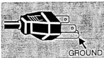
This projector is equipped with a grounding type AC line plug. Should you be unable to insert the plug into the outlet, contact your electrician. Do not defeat the safety purpose of this grounding type plug.
Follow all warnings and instructions marked on the projectors.
For added protection to the projector during a lightning storm, or when it is left unattended and unused for long periods of time, unplug it from the wall outlet. This will prevent damage due to lightning and powerline surges.

natural_image
Symbolic illustration of a person using a ladder to lift a box, enclosed in a circle with no text or symbols.An appliance and cart combination should be moved with care. Quick stops, excessive force, and uneven surfaces may cause the appliance and cart combination to overturn.
TABLE OF CONTENTS
| PAGE | PAGE | ||
| INTRODUCTION | 5 | SOUND MUTE FUNCTION | 28 |
| COMPATIBILITY | 5 | ZOOM ADJUSTMENT | 28 |
| IMAGE RESOLUTION | 5 | FOCUS ADJUSTMENT | 28 |
| PORTABILITY | 5 | NORMAL PICTURE FUNCTION | 28 |
| UNPACKING THE PROJECTOR | 5 | FREEZE PICTURE FUNCTION | 28 |
| TRADEMARKS | 5 | FINE SYNC ADJUSTMENT | 28 |
| POWER REQUIREMENT | 6 | MENU OPERATION | 29-46 |
| DESCRIPTION | 7 | MODE SELECT | 29 |
| SETTING-UP THE PROJECTOR | 8-9 | SOUND ADJUSTMENT | 30 |
| POSITIONING | 8 | LANGUAGE ADJUSTMENT | 30 |
| ROOM LIGHT | 8 | MENU EXIT | 30 |
| VENTILATION | 8 | COLOR SYSTEM SELECT | 31 |
| LEVELING AND ELEVATING ADJUSTMENTS | 8 | PICTURE IMAGE ADJUSTMENT | 32 |
| MOVING THE PROJECTOR | 9 | PICTURE SCREEN ADJUSTMENT | 33 |
| CONNECTING THE PROJECTOR | 10-17 | COMPUTER SYSTEM SELECT | 34 |
| CONNECTING THE COMPUTER | 10-14 | COMPATIBLE COMPUTER SPECIFICATION | 35 |
| Connecting an IBM-compatible desktop computer | 11 | PICTURE IMAGE ADJUSTMENT | 36 |
| Connecting a Macintosh desktop computer | 12 | PICTURE POSITION ADJUSTMENT | 37 |
| Connecting an IBM-compatible laptop computer | 13 | PC ADJUSTMENT | 38-41 |
| Connecting a Macintosh PowerBook computer | 14 | AUTO IMAGE FUNCTION | 42 |
| CONNECTING THE VIDEO EQUIPMENT | 15-16 | PICTURE SCREEN ADJUSTMENT | 43 |
| CONNECTING AN EXTERNAL SPEAKER | 17 | OTHER FUNCTION SETTING | 44-46 |
| OPERATION OF CONTROLS | 18-20 | AUTO RETRACT | 44-45 |
| TOP OF THE PROJECTOR | 18-19 | BLUE BACK | 44-45 |
| REAR OF THE PROJECTOR | 20 | DISPLAY | 44-45 |
| OPERATION OF REMOTE CONTROL | 21-23 | CEILING | 44-45 |
| REMOTE CONTROL BATTERY INSTALLATION | 23 | REAR | 44-45 |
| USING THE REMOTE CONTROL UNIT | 23 | LAMP AGE | 46 |
| CONTROL THE PROJECTOR | 24-26 | AIR FILTER CARE AND CLEANING | 47 |
| DIRECT OPERATION | 24 | TEMPERATURE WARNING INDICATOR | 47 |
| MENU OPERATION | 25-26 | LAMP REPLACEMENT | 48 |
| USING THE PROJECTOR | 27-46 | CLEANING THE LENS | 49 |
| TO TURN ON THE PROJECTOR | 27 | TROUBLESHOOTING | 49-50 |
| TO TURN OFF THE PROJECTOR | 27 | TECHNICAL SPECIFICATIONS | 51 |
| DIRECT OPERATION | 28 | ||
| MODE SELECT | 28 | ||
| SOUND VOLUME ADJUSTMENT | 28 |
INTRODUCTION
The projector is a multimedia projector designed for portability, durability, and ease of use. The projector utilizes built-in multimedia features, a palette of 16.7 million colors, and active matrix liquid crystal display (LCD) technology.
DMPATIBILITY
The projector is compatible with many different types of personal computers and video devices, including;
- IBM-compatible computers, including laptops, up to 1280 × 1024 resolution.
- Apple Macintosh and PowerBook computers up to 1280 × 1024 resolution.
- Various VCRs, video disc players, video cameras, satellite TV tuners or other AV equipment using any of the worldwide video standards, including NTSC, NTSC4.43, PAL and SECAM.
IMAGE RESOLUTION
The resolution of the projector's projected image is 1024 × 768 . The projector displays computer images just as they appear on your computer's monitor. Screen resolutions between 1024 × 768 and 1280 × 1024 are compressed to 1024 × 768 . The projector cannot display screen resolutions above 1280 × 1024 . If your computer's screen resolution is higher than 1280 × 1024 , reset it to a lower resolution before you connect the projector.
PORTABILITY
The projector is extremely compact in size and weight. Having a sophisticated shape like an attaché case with a retractable carrying handle, the projector will help you make powerful presentations wherever you go. To strengthen the portability, the LENS RETRACT function is designed to protect the lens from being damaged during transportation. With this function, the lens is pulled in when not in use.
UNPACKING THE PROJECTOR
The projector comes with the parts shown listed below. Check to make sure all are included. If any parts are missing, contact an authorized dealer or service station.
- Owner's Manual.
AC Power Cord.
Remote Control Transmitter Unit and batteries. - Lens Cover.
● Protective Dust Cover. - VGA Cable.
• VGA/MAC Adapter. - Mouse Cable for PS/2 port.
- Mouse Cable for serial port.
- Mouse Cable for ADB port.
TRADEMARKS
- Apple, Macintosh, and PowerBook are trademarks or registered trademarks of Apple Computer, Inc.
- IBM and PS/2 are trademarks or registered trademarks of International Business Machines, Inc.
POWER REQUIREMENTS
Your projector uses nominal input voltages of 100-120 VAC. The projector automatically selects the correct input voltage. The projector is designed to work with single-phase power systems having a grounded neutral conductor. To reduce the risk of electrical shock, do not plug into any other type of power system. Consult your authorized dealer or service station if you are not sure what type of power is supplied to your building.
natural_image
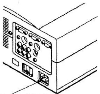
Line drawing of a computer tower rear panel with ports and connectors (no text or symbols)Connect the AC power supply cord (supplied) to the projector.
Projector side (Female)
natural_image
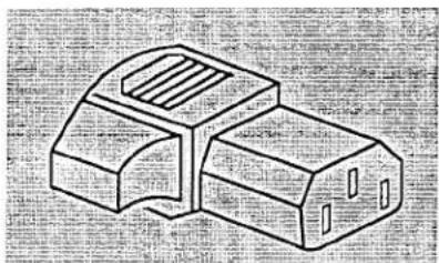
Isometric line drawing of a mechanical component with no visible text or symbolsAC outlet side (Male)
natural_image
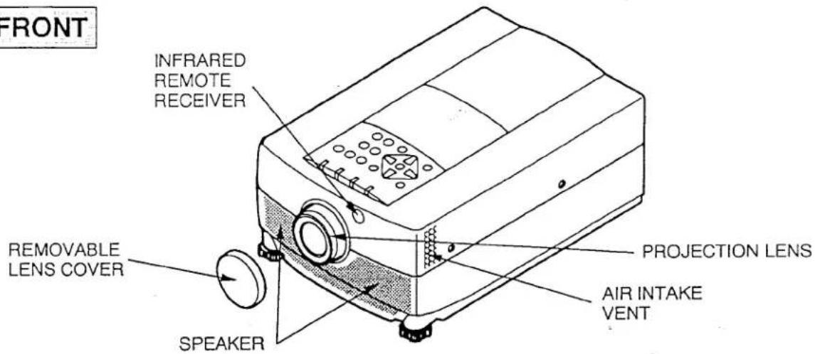
Pure mechanical component diagram without any text, numbers, or symbolsFRONT
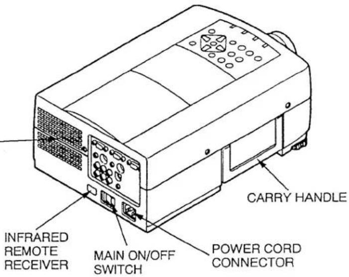
REAR
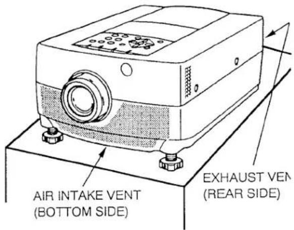
EXHAUST VENT

CAUTION HOT AIR!
Air blown from the exhaust vent is hot. Observe the following when handling your projector or choosing a location to install it.
- Keep heat-sensitive objects away from the exhaust port.
- If you set the projector on top of a metallic surface, the surface will become hot because of the hot air exhaust. Be careful when handling.
- Do not touch the cabinet near to the exhaust vent, and especially screws and metallic parts. These parts will become hot while the projector is used.
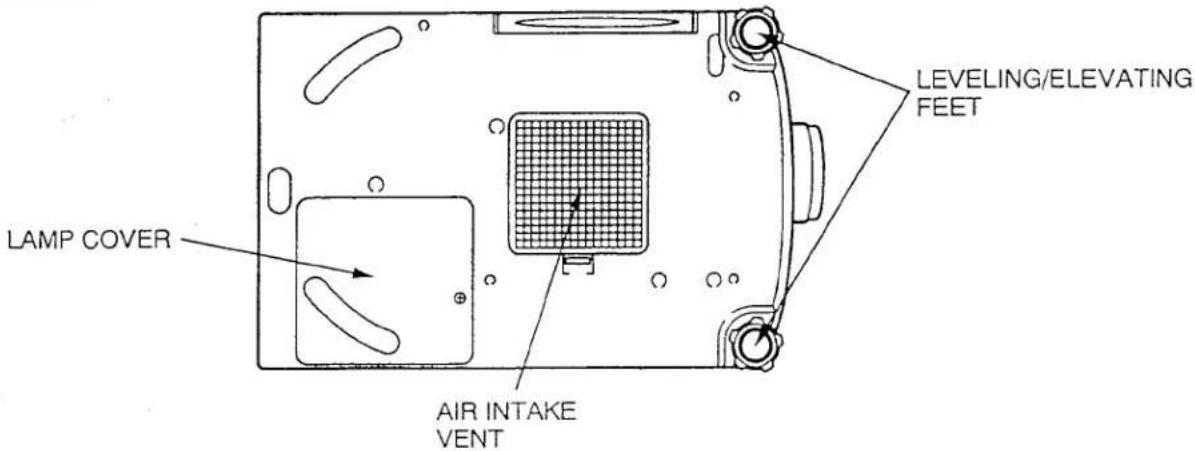
BOTTOM
SETTING-UP THE PROJECTOR
POSITIONING:
- This projector is basically designed to project on a flat projection surface.
- This projector can be focused from 3.6' (1.1m) \~ 47' (14.3m).
- Use the illustration below as an example when positioning the projector to the screen.
ROOM LIGHT
Ideally the projector should be placed in a room with limited light. Picture quality will be directly affected by lighting conditions.
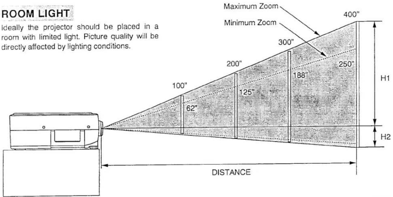
| Screen Size | Max. Zoom | 32" | 60" | 100" | 150" | 200" | 300" | 400" |
| Min. Zoom | 20" | 37" | 62" | 94" | 125" | 188" | 250" | |
| Distance | 3.6'(1.1 m) | 6.9'(2.1 m) | 11.8'(3.6 m) | 17.8'(5.4 m) | 23.7'(7.2 m) | 35.2'(10.7 m) | 47'(14.3 m) | |
| Screen Size(W × H) inch | 20" | 60" | 100" | 150" | 200" | 300" | 400" |
| 16 × 12 | 49 × 36 | 80 × 60 | 120 × 90 | 160 × 120 | 240 × 180 | 320 × 240 | |
| Height (H1) | 10.7 inch | 32 inch | 53 inch | 80 inch | 106 inch | 160 inch | 212 inch |
| Height (H2) | 1.3 inch | 4 inch | 7 inch | 10 inch | 14 inch | 20 inch | 28 inch |
VENTILATION
Although this projector has a cooling fan to protect it from overheating, please be careful to set the projector so that it can cool properly and you can avoid a risk of fire and malfunction.

- Do not cover the vents with papers or other materials.
- Keep the rear grill at least 3.3' (1m) away from any object.
- Make sure that there are no objects under the projector. An object under the projector may prevent the projector from taking the cooling air through the bottom vent.
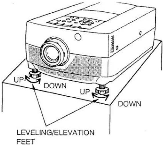
LEVELING AND ELEVATING ADJUSTMENTS
Picture adjustments can be made with the two leveling/elevating feet. Adjustments of up to 6° are possible by rotating the feet on the bottom of the projector.
I el the projector, by rotating the two feet (left and right) on the bottom of the projector.
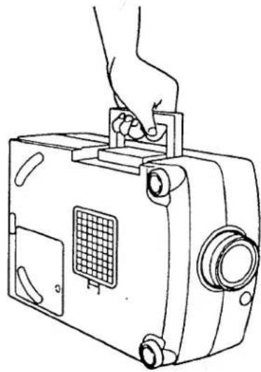
MOVING THE PROJECTOR
Use the carry handle when moving the projector.
Replace the lens cover when moving the projector to prevent damage to the lens.
natural_image
Line drawing of a hand holding a portable electronic device with a grid panel and ports (no text or symbols)CONNECTING THE PROJECTOR
Your projector is equipped with various audio/video inputs and outputs including Computer HDB15-pin (VGA) terminals, Monitor HDB15-pin (VGA) terminals and S-VHS video.
CONNECTING THE COMPUTER
CONNECTING TO THE COMPUTER INPUT HDB15-PIN (VGA) TERMINALS (1 and 2)
Personal computers can be connected to the HDB15-pin (VGA) terminal on the projector.
- Connect the computer to these terminals using the VGA cable and VGA/MAC adapter (provided).
WARNING: For projectors, the VGA cable provided is designed to reduce RFI (Radio Frequency Interference) emissions. For regulatory compliance reasons, this cable must be used and must not be replaced by any other cable.
CONNECTING TO THE MONITOR OUTPUT HDB15-PIN (VGA) TERMINAL
This terminal contain the information that is viewed on the screen.
Monitor can be connected to the HDB15-pin (VGA) terminal on the projector.
- Connect the monitor to this terminal using the monitor cable (not provided).
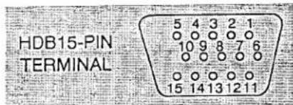
Pin No./Signal
1 Red input
2 Green input
3 Blue input
4 Sense 2
5 Ground (Horiz. sync.)
6 Ground (Red)
7 Ground (Green)
8 Ground (Blue)
Pin No./Signal
9 Non Connect
10 Ground (Vert. sync.)
11 Sense 0
12 Sense 1
13 Horiz. sync.
14 Vert. sync.
15 Reserved
CONNECTING TO THE COMPUTER AUDIO INPUT JACKS (1 and 2)
- Connect audio outputs from your computer to these jacks using the audio cable (not provided).
CONNECTING TO THE MULTI-POLE 12-PIN (CONTROL PORT) CONNECTORS (1 and 2)
- If you wish to control the computer by the projector's remote control unit, you must connect a cable (three type cables provided) from control port (PS/2, Serial or ADB port) on your computer to this connector.
CONTROL PORT
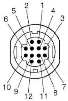
| PS/2 Port | Serial Port | ADB Port | |
| 1 | —— | TxD | —— |
| 2 | CLK | —— | ADB |
| 3 | DATA | —— | —— |
| 4 | —— | —— | —— |
| 5 | —— | ※ RxD | —— |
| 6 | —— | —— | —— |
| 7 | —— | READY | —— |
| 8 | —— | —— | —— |
| 9 | GND | GND | GND |
| 10 | —— | —— | —— |
| 11 | —— | —— | —— |
| 12 | —— | —— | —— |
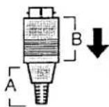
CONTROL PORT CABLE REMOVAL HINT
To disconnect the control port cable connector proceed as follows.
- Hold the portion (A) of the connector.
- Pull the portion (B) to disconnect.
※ NOTE: The RxD port (5 pin on the Serial Port) is provided on control port 2 connector only. If you control the projector by computer, you must connect control port 2 connector.
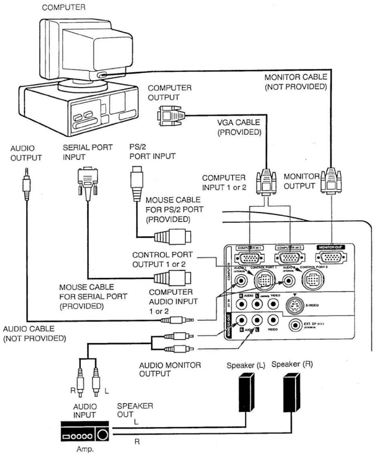
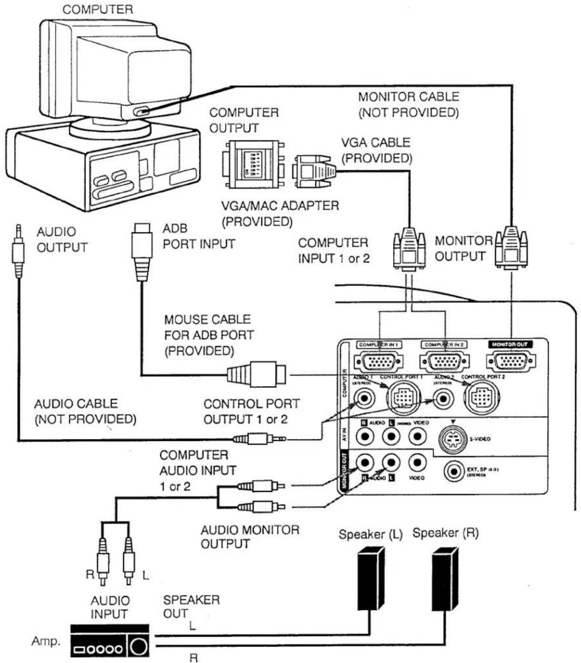
Connecting an IBM-compatible desktop computer
flowchart
graph TD
    A["COMPUTER"] --> B["COMPUTER OUTPUT"]
    B --> C["VGA CABLE (PROVIDED)"]
    C --> D["MONITOR CABLE (NOT PROVIDED)"]
    D --> E["MONITOR OUTPUT"]
    E --> F["COMPUTER INPUT 1 or 2"]
    F --> G["MOUSER CABLE FOR PS/2 PORT (PROVIDED)"]
    G --> H["CONTROL PORT OUTPUT 1 or 2"]
    H --> I["COMPUTER AUDIO INPUT 1 or 2"]
    I --> J["AUDIO CABLE (NOT PROVIDED)"]
    J --> K["AUDIO INPUT"]
    K --> L["Speaker OUT"]
    L --> M["R"]
    M --> N["Audio CABLE"]
    N --> O["Audio Monitor OUTPUT"]
    O --> P["Speaker (L)"]
    P --> Q["Speaker (R)"]
    Q --> R["Extr. SP (HD) (ISTENCE)"]
    R --> S["S-WIDEO"]
    S --> T["AUDIO OUT"]
    T --> U["AUDIO"]
    U --> V["L"]
    V --> W["Audio INPUT"]
    W --> X["Audio CABLE FOR SERIAL PORT (PROVIDED)"]
    X --> Y["MOUSER CABLE FOR PS/2 PORT (PROVIDED)"]
    Y --> Z["COMPUTER INPUT 1 or 2"]
    Z --> AA["COMPUTER OUTPUT 1 or 2"]
    AA --> AB["AUDIO CABLE (NOT PROVIDED)"]
    AB --> AC["Audio CABLE"]
    AC --> AD["L"]
NOTE: The hook up should be done as per the above illustration. After hook up, turn on the projector, monitor, computer, in that order.
Connecting a Macintosh desktop computer
flowchart
graph TD
    A["COMPUTER"] --> B["COMPUTER OUTPUT"]
    B --> C["VGA MAC ADAPTER (PROVIDED)"]
    C --> D["MONITOR CABLE (NOT PROVIDED)"]
    D --> E["MONITOR OUTPUT"]
    E --> F["COMPUTER INPUT 1 or 2"]
    F --> G["MOUSE CABLE FOR ADB PORT (PROVIDED)"]
    G --> H["AUDIO CABLE (NOT PROVIDED)"]
    H --> I["CONTROL PORT OUTPUT 1 or 2"]
    I --> J["COMPUTER AUDIO INPUT 1 or 2"]
    J --> K["AUDIO MONITOR OUTPUT"]
    K --> L["Speaker (L)"]
    K --> M["Speaker (R)"]
    N["Audio INPUT"] --> O["Audio CABLE (NOT PROVIDED)"]
    P["Speaker OUT"] --> Q["Audio MONITOR OUTPUT"]
    R["Audio OUTPUT"] --> S["AUDIO CABLE (NOT PROVIDED)"]
    T["Audio CABLE"] --> U["CONTROL PORT OUTPUT 1 or 2"]
    V["MONITOR OUT"] --> W["MONITOR CABLE (NOT PROVIDED)"]
    X["MONITOR CABLE"] --> Y["MONITOR OUTPUT"]
    Z["Speaker (L)"] --> AA["Speaker (R)"]
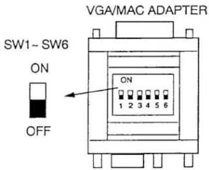
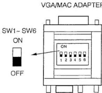
Set the slide switches as shown in the table below depending on the RESOLUTION MODE that you want to use before you turn on the projector and computer.
| RESOLUTION MODE | SW1 | SW2 | SW3 | SW4 | SW5 | SW6 |
| 13" MODE (640 × 480) | ON | OFF | OFF | OFF | OFF | OFF |
| 16" MODE (832 × 624) | OFF | OFF | OFF | OFF | OFF | ON |
| 19" MODE (1024 × 768) | OFF | OFF | OFF | ON | OFF | OFF |
| 21" MODE (1152 × 870) | ON | ON | ON | OFF | OFF | OFF |
NOTE: The hook up should be done as per the above illustration. After hook up, turn on the projector, monitor, computer, in that order.
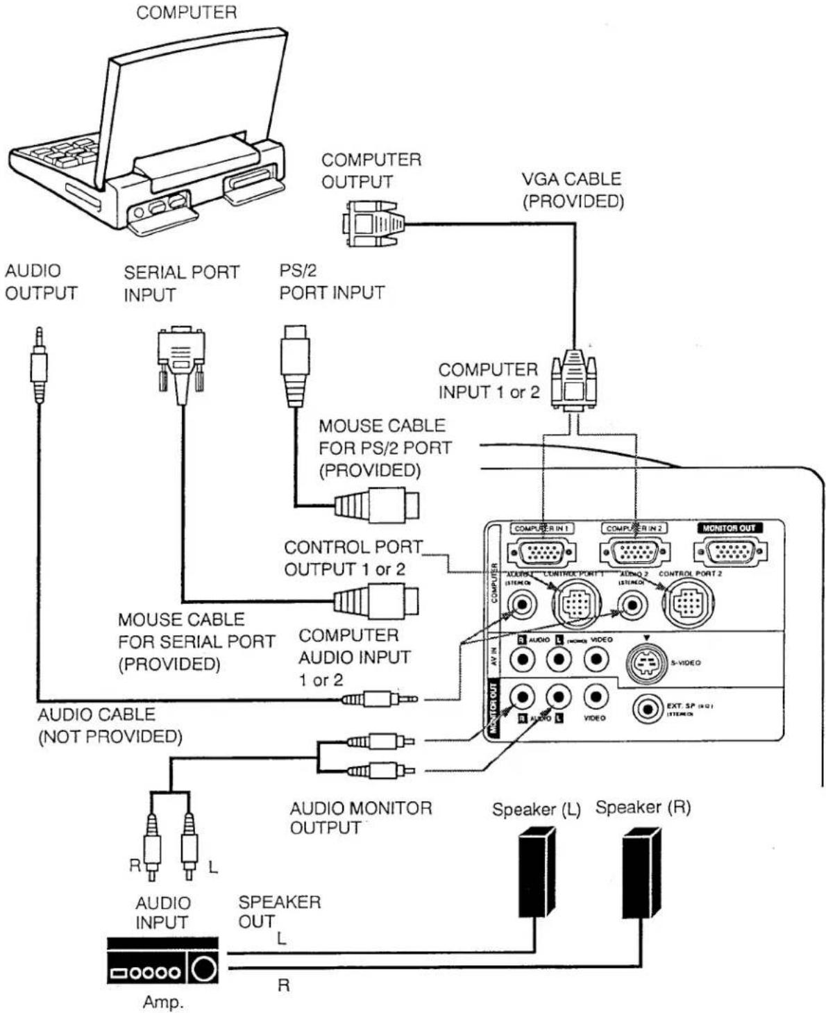
Connecting an IBM-compatible laptop computer
flowchart
graph TD
    A["COMPUTER"] --> B["COMPUTER OUTPUT"]
    B --> C["VGA CABLE (PROVIDED)"]
    C --> D["COMPUTER INPUT 1 or 2"]
    D --> E["MOUSE CABLE FOR PS/2 PORT (PROVIDED)"]
    E --> F["CONTROL PORT OUTPUT 1 or 2"]
    F --> G["MOUSE CABLE FOR SERIAL PORT (PROVIDED)"]
    G --> H["COMPUTER AUDIO INPUT 1 or 2"]
    H --> I["AUDIO CABLE (NOT PROVIDED)"]
    I --> J["AUDIO MONITOR OUTPUT"]
    J --> K["Speaker (L)"]
    J --> L["Speaker (R)"]
    M["Audio INPUT"] --> N["Audio INPUT"]
    O["Speaker OUT"] --> P["R"]
    Q["Audio CABLE"] --> R["MOUSE CABLE FOR PS/2 PORT (PROVIDED)"]
    S["Audio CABLE"] --> T["MOUSE CABLE FOR SERIAL PORT (PROVIDED)"]
NOTE: The hook up should be done as per the above illustration. After hook up, turn on the projector, computer, in that order.
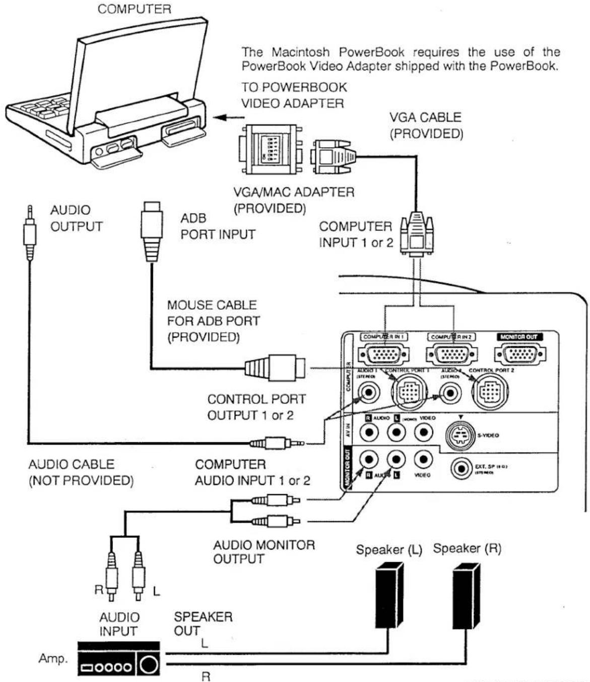
Connecting a Macintosh PowerBook computer
flowchart
graph TD
    A["COMPUTER"] --> B["VGA/CABLE (PROVIDED)"]
    B --> C["COMPUTER INPUT 1 or 2"]
    C --> D["MONITOR OUT"]
    D --> E["Speaker (L)"]
    D --> F["Speaker (R)"]
    G["AUDIO OUTPUT"] --> H["ADB PORT INPUT"]
    H --> I["MOUSE CABLE FOR ADB PORT (PROVIDED)"]
    I --> J["CONTROL PORT OUTPUT 1 or 2"]
    J --> K["AUDIO CABLE (NOT PROVIDED)"]
    K --> L["AUDIO INPUT"]
    L --> M["Speaker OUT"]
    M --> N["Audio."]
    style A fill:#f9f,stroke:#333
    style B fill:#ccf,stroke:#333
    style C fill:#cfc,stroke:#333
    style D fill:#fcc,stroke:#333
    style E fill:#cff,stroke:#333
    style F fill:#ffc,stroke:#333
    style G fill:#fff,stroke:#000
    style H fill:#fff,stroke:#000
    style I fill:#fff,stroke:#000
    style J fill:#fff,stroke:#000
    style K fill:#fff,stroke:#000
    style L fill:#fff,stroke:#000
    style M fill:#fff,stroke:#000
    style N fill:#fff,stroke:#000
Set the slide switches as shown in the table below depending on the RESOLUTION MODE that you want to use before you turn on the projector and computer.
| RESOLUTION MODE | SW1 | SW2 | SW3 | SW4 | SW5 | SW6 |
| 13" MODE (640 × 480) | ON | OFF | OFF | OFF | OFF | OFF |
| 16" MODE (832 × 624) | OFF | OFF | OFF | OFF | OFF | ON |
| 19" MODE (1024 × 768) | OFF | OFF | OFF | ON | OFF | OFF |
| 21" MODE (1152 × 870) | ON | ON | ON | OFF | OFF | OFF |
NOTE: The hook up should be done as per the above illustration. After hook up, turn on the projector, computer, in that order.
CONNECTING THE VIDEO EQUIPMENT
CONNECTING TO THE AV INPUT JACKS
Connect to the video and audio outputs of a VCR, video disc player, video camera, satellite TV tuner or other AV equipment.
- Connect audio/video outputs from external sources to these input jacks using the audio/video cable.
- If the audio signal from the AV equipment is stereo, be sure to connect the right and left channels to the respective right and left audio input jacks.
- If the external audio signal is monaural, connect it to the left jack.
S-VHS FORMAT VCR CONNECTION
The AV input includes an extra video input jack marked S-VIDEO to allow connection to an S-VHS format VCR that has separate Y/C video signals. The S-VIDEO jack has priority over the VIDEO jack.
CONNECTING TO THE VIDEO MONITOR OUTPUT JACK
This jack will contain the video information of the selected program source video only. If you select program source Computer 1 or Computer 2, there is no signal.
Connect video input from AV equipment to this jack by RCA cable.
Whenever the S-VIDEO signal source is viewed on the screen, the video signal available at the MONITOR OUTPUT jack will be in black and white (monochrome).
CONNECTING TO THE AUDIO MONITOR OUTPUT JACKS
These jacks will contain the audio information of the selected program source being viewed on the screen (Computer 1, Computer 2 or Video 1). If you have selected program source Computer 1 the audio signal connected to the Computer 1 audio input jack will be available at the audio monitor output jacks.
- If the audio input of the audio equipment is stereo, be sure to connect the right and left channels to the respective right and left jacks.
- If the audio input of the audio equipment is monaural, connect it to the left jack.
Connecting the Video Equipment
VIDEO EQUIPMENT
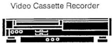

Satellite TV Tuner
flowchart
graph TD
    A["Audio INPUT"] --> B["Speaker (L)"]
    C["Audio OUTPUT"] --> D["Speaker (R)"]
    E["Audio INPUT"] --> F["Audio Monitor OUTPUT"]
    G["Audio OUTPUT"] --> H["Audio Monitor OUTPUT"]
    I["Audio INPUT"] --> J["Monitor"]
    K["Audio OUTPUT"] --> L["Monitor"]
    M["S-VHS VCR"] --> N["S-VIDEO OUTPUT"]
    O["S-VIDEO INPUT"] --> P["S-VIDEO OUTPUT"]
    Q["S-VIDEO OUT"] --> R["S-VIDEO OUTPUT"]
    S["COMPUTER IN 1"] --> T["AUDIO 1 ESTEREO"]
    U["COMPUTER IN 2"] --> V["AUDIO 2 ESTEREO"]
    W["MONITOR OUT"] --> X["MONITOR"]
    Y["AV IN"] --> Z["MONITOR OUT"]
    AA["AV IN"] --> AB["MONITOR OUT"]
    AC["AV IN"] --> AD["MONITOR OUT"]
    AE["AV IN"] --> AF["MONITOR OUT"]
NOTE: The hook up should be done as per the above illustration. After hook up, turn on the projector, video equipment, in that order.
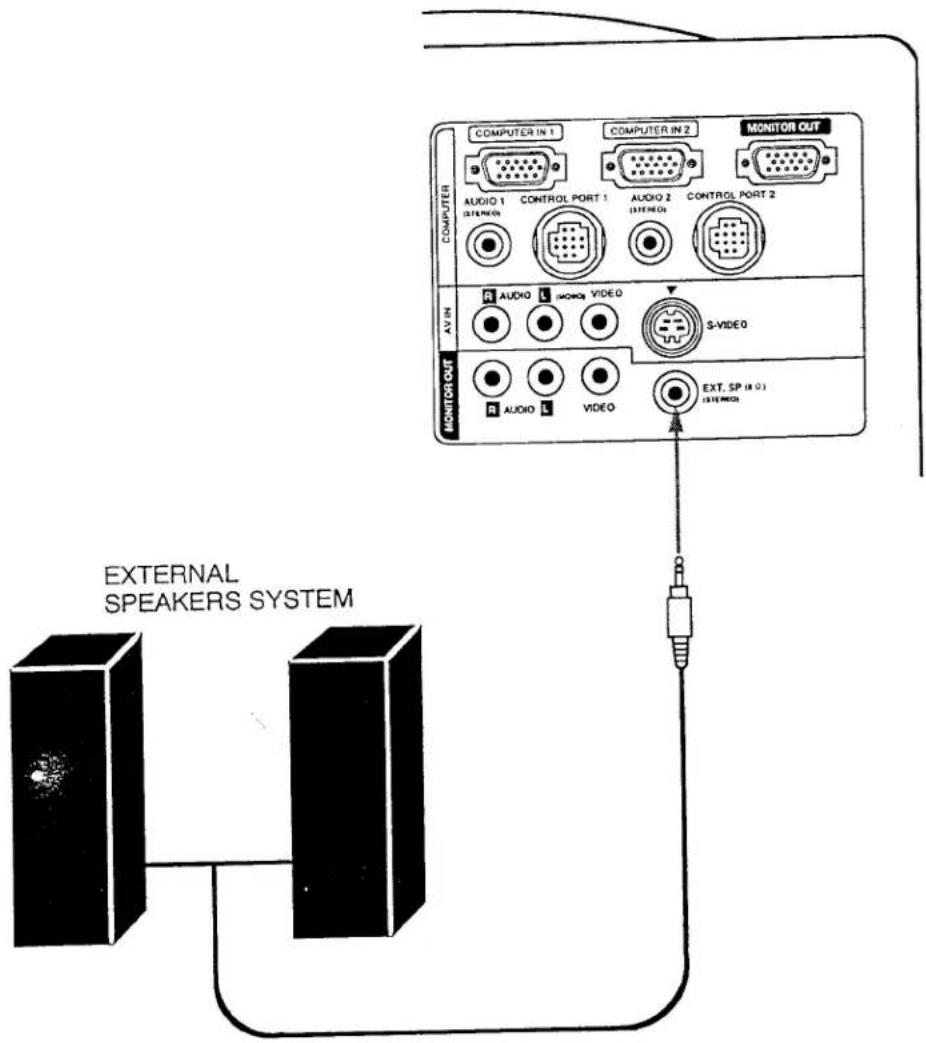
CONNECTING AN EXTERNAL SPEAKER
CONNECTING TO THE EXT. SP. JACK (3.5mm mini stereo type)
This jack contains the audio information of the viewed image. Use it to connect an external speaker system when using this jack. It will turn off the audio from the internal speaker.
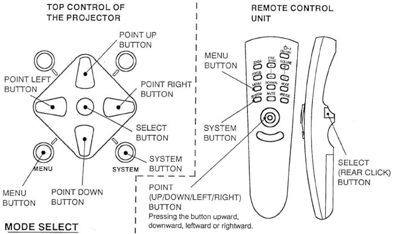
TOP OF THE PROJECTOR
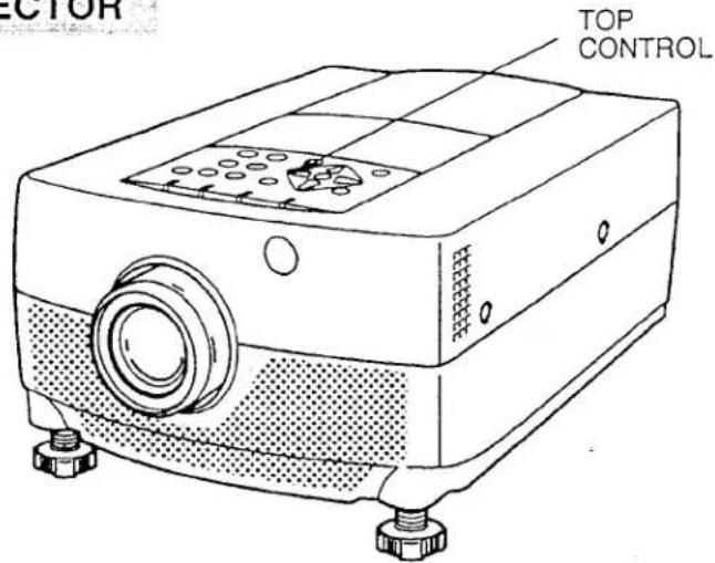
TOP CONTROL
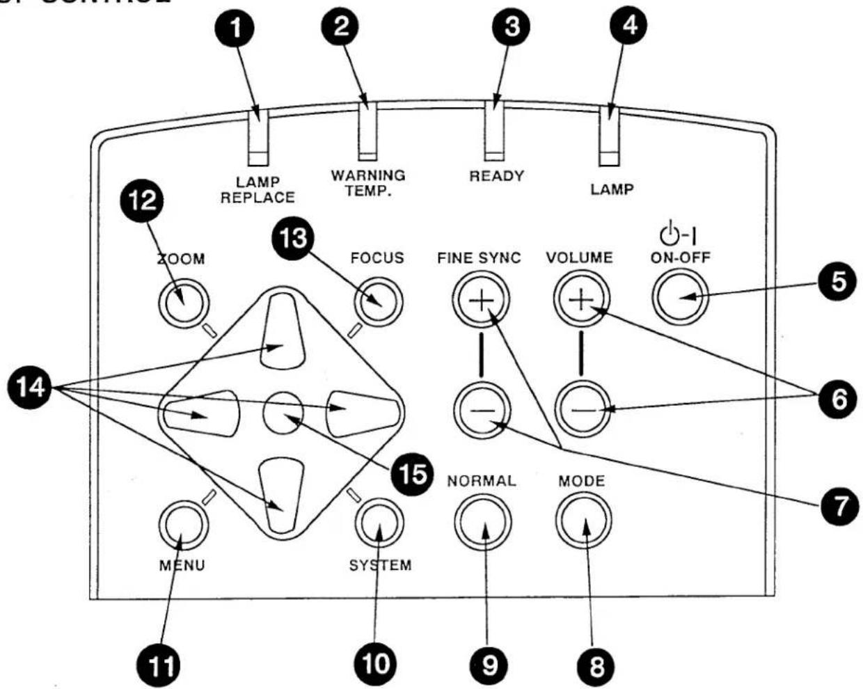
1 LAMP REPLACEMENT INDICATOR Light is orange when projection lamp is nearing end of service life.
2 TEMPERATURE WARNING INDICATOR Flashes red when internal projector temperature is too high.
3 READY INDICATOR Light is green when projector lamp is ready to be turned on.
4 LAMP POWER INDICATOR Light is dim when the projector is on. Light is brightened when the projector is in stand-by mode.
⑤ LAMP POWER ON/OFF BUTTON Used to turn projection lamp on or off.
6 VOLUME BUTTONS Used to adjust volume.
7 FINE SYNC BUTTONS Used to adjust fine sync.
8 MODE BUTTON Used to select video source. (Computer 1, Computer 2 or Video 1 Input)
9 NORMAL BUTTON Used to reset to normal picture adjustment preset by factory.
10 SYSTEM BUTTON
- Computer Mode Use this button, the POINT UP/DOWN/LEFT/RIGHT buttons and the SELECT button to select computer system. - VIDEO Mode Use this button, the POINT UP/DOWN/LEFT/RIGHT buttons and the SELECT button to select color system.
1 MENU BUTTON
This button will activate the MENU operation. Use this button, the POINT UP/DOWN/LEFT/RIGHT buttons and the SELECT button to make adjustments to the projector's setting in MENU operation.
12 ZOOM BUTTON
Used to select power zoom lens adjust.
13 FOCUS BUTTON
Used to select focus adjust.
14 POINT UP/DOWN/LEFT/RIGHT BUTTONS
- To select an item on the MENU that you want to adjust. To select an item, move the arrow by pressing these buttons (UP, DOWN, LEFT or RIGHT). - Used to operate power zoom lens or power focus system. (Pressing these button either UP or DOWN)
15 SELECT BUTTON
This button has different functions depending on when used. This button is used to execute the item selected, to increase or decrease the values in certain items such as CONTRAST or BRIGHTNESS.
REAR OF THE PROJECTOR
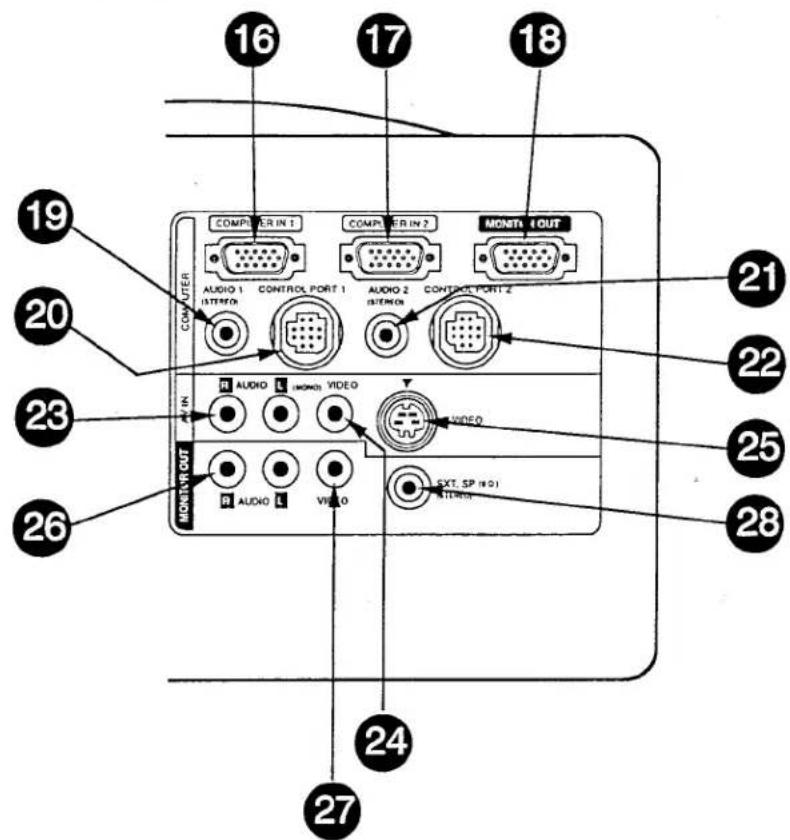
16 COMPUTER INPUT-1 TERMINAL
Used to connect a computer to the projector.
17 COMPUTER INPUT-2 TERMINAL
Used to connect a computer to the projector.
18 MONITOR OUTPUT TERMINAL
Used to connect a monitor to the projector.
19 COMPUTER AUDIO INPUT-1 JACK mini stereo type
Used to connect a computer audio input to the projector.
20 CONTROL PORT-1 CONNECTOR
Used to connect a mouse cable to the projector.
21 COMPUTER AUDIO INPUT JACK 2
mini stereo type
Used to connect a computer audio input to the projector.
22 CONTROL PORT-2 CONNECTOR (SERIAL PORT)
Used to connect a mouse cable to the projector.
23 AUDIO INPUT JACKS
Used to connect an audio input to the projector.
24 VIDEO INPUT JACK
Used to connect a video source to the projector.
25 S-VIDEO INPUT JACK
Used to connect a S-VHS video source to the projector.
26 AUDIO MONITOR OUTPUT JACKS
Permits audio connection to a monitor.
27 VIDEO MONITOR OUTPUT JACK
Permits video connection to a monitor.
28 EXT. SP. JACK (3.5 mm mini stereo type)
Used to connect a external speakers system.
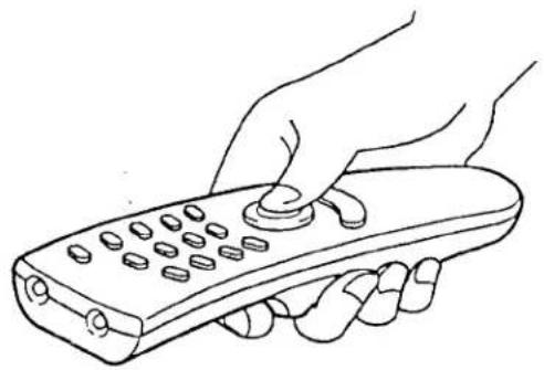
OPERATION OF REMOTE CONTROL
This remote control unit can be used not only as a remote control for the projector operation but also as a wireless mouse for PC. The remote control unit has a pointing pad and two click buttons. The wireless mouse function is activated when you do not adjust the setting by using the MENU operation.
NOTE: To use the wireless mouse function, connect the attached cable between the projector and your PC since the mouse control signal is transferred through the projector. Use the proper cable and follow the instruction as described in section "CONNECTING THE PROJECTOR" on pages 10 \~ 14 depending on your PC.
natural_image
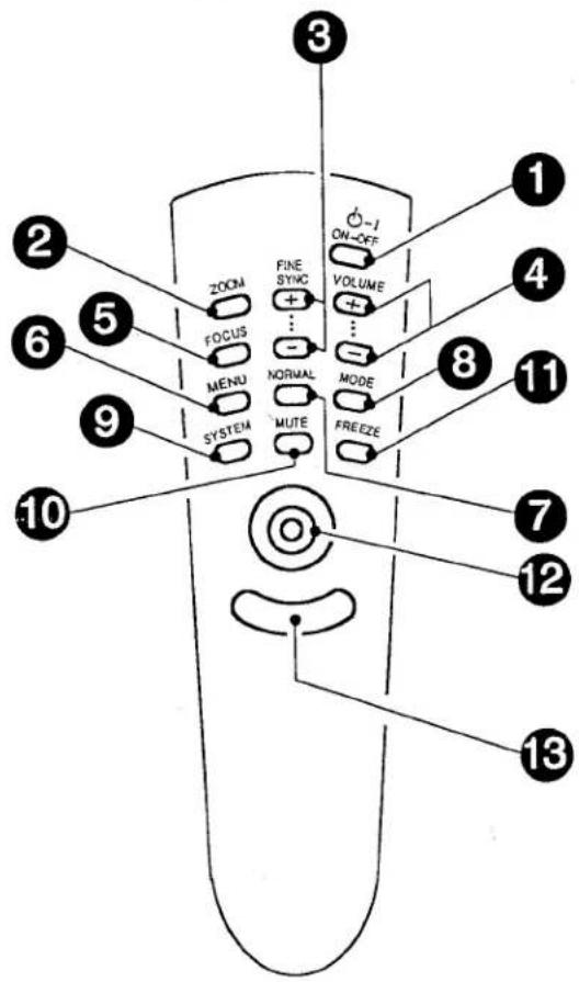
Line drawing of a hand holding a remote control with buttons (no text or symbols)FRONT
SIDE
LAMP POWER ON/OFF BUTTON Used to turn the projection lamp on or off.
2 ZOOM BUTTON Used to select power zoom lens adjust.
3 FINE SYNC BUTTONS Used to adjust fine sync.
4 VOLUME BUTTONS Used to adjust volume.
5 FOCUS BUTTON Used to select focus adjust.
6 MENU BUTTON This button will activate the MENU operation. Use this button, the POINT UP/DOWN/LEFT/RIGHT button and the SELECT (REAR CLICK) button to make adjustments to the projector's setting in MENU operation.
7 NORMAL BUTTON Use to reset to normal picture adjustment preset by factory.
8 MODE BUTTON Used to select video source. (Computer 1, Computer 2 or Video 1 Input)
9 SYSTEM BUTTON ● Computer Mode Use this button, the POINT UP/DOWN/LEFT/RIGHT button and the computer system.
- VIDEO Mode Use this button, the POINT UP/DOWN/LEFT/RIGHT button and the SELECT (REAR CLICK) button to select color system.
10 SOUND MUTE BUTTON Used to mute sound.
11 FREEZE BUTTON Use this button to freeze on-screen image.
12 POINTING PAD (POINT UP/DOWN/LEFT/RIGHT BUTTON) When in use as a remote for the projector
To select an item on the MENU that you want to adjust. To select an item, move the arrow by pressing the pad upward, downward, leftward or rightward. Used to operate power zoom lens or power focus system by pressing the pad either upward or downward.
When in use as a wireless mouse Used to move the pointer. The pointer is moved according to the direction you are pressing.
13 FRONT CLICK BUTTON This button has the same function as the right button in a PC mouse. Pressing this button does not affect any operation when in MENU mode.
14 SELECT (REAR CLICK) BUTTON When in use as a remote for the projector. This button has different functions depending on when used. This button is used to execute the item selected, to increase or decrease the values in certain items such as CONTRAST or BRIGHTNESS.
When in use as a wireless mouse This button has the same function as the left button in a PC mouse.
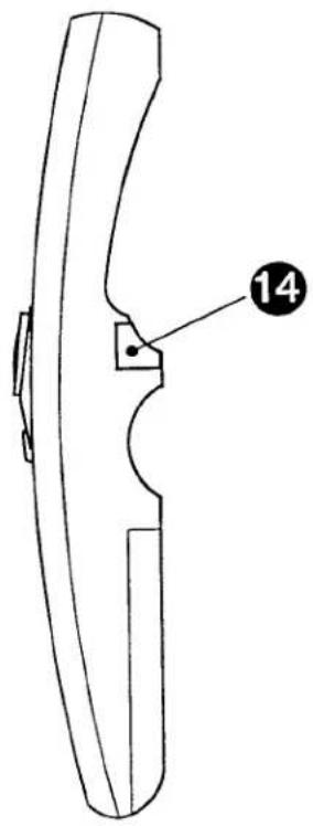
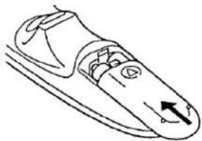
REMOTE CONTROL BATTERY INSTALLATION
1
Remove the battery compartment lid.

natural_image
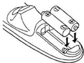
Line drawing of a shoe handle with a circular button and arrow indicating direction (no text or symbols)2
Slide the batteries into the compartment.
Note: For correct polarity (+ and - terminal), be sure the battery terminals are in contact with the pins in the compartment.
natural_image
Technical line drawing of a mechanical component with two arrows indicating assembly or force direction (no text or symbols)3
Replace the compartment lid.
natural_image
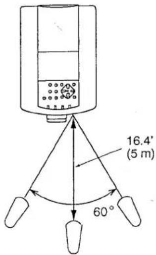
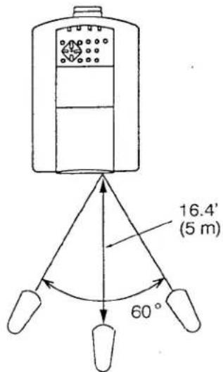
Line drawing of a mechanical component with a curved handle and internal features (no text or symbols)USING THE REMOTE CONTROL UNIT
Point the remote control toward the projector (Receiver window) whenever pressing the buttons. Maximum operating range for the remote control is about 16.4' (5m) and 60° front and rear of the projector.

To insure safe operation, please observe the following precautions:
• Use (2) AA type manganese or alkaline batteries.
- Change two batteries at the same time.
- Do not use a new battery with a used battery.
- Avoid contact with water.
- Do not drop the remote control unit.
- If batteries have leaked on the remote control, carefully wipe the case clean and load new batteries.
CONTROL THE PROJECTOR
The projector has two types of operation: DIRECT OPERATION and MENU OPERATION. DIRECT OPERATION allows you to operate the projector by using one button without showing the MENU. In MENU OPERATION mode, you display menus where you can adjust the projector's settings. Follow the instruction for each control.
DIRECT OPERATION
| ADJUST ITEM | TOP CONTROL OF THE PROJECTOR | REMOTE CONTROL UNIT |
| LAMP POWER ON/OFF | LAMP POWER ON-OFF BUTTON | LAMP POWER ON-OFF BUTTON |
| MODE SELECT | MODE BUTTON | MODE BUTTON |
| SOUND VOLUME | VOLUME (+) and ( - ) BUTTONS | VOLUME (+) and ( - ) BUTTONS |
| SOUND MUTE | NOT AVAILABLE | MUTE BUTTON |
| ZOOM | ZOOM BUTTON POINT UP/DOWN BUTTONS | ZOOM BUTTON POINT (UP/DOWN) BUTTON |
| FOCUS | FOCUS BUTTON POINT UP/DOWN BUTTONS | FOCUS BUTTON POINT (UP/DOWN) BUTTON |
| NORMAL PICTURE | NORMAL BUTTON | NORMAL BUTTON |
| FREEZE PICTURE | NOT AVAILABLE | FREEZE BUTTON |
| FINE SYNC. | FINE SYNC. (+) and ( - ) BUTTONS | FINE SYNC. (+) and ( - ) BUTTONS |
| MODE SELECT | MENU BUTTONPOINT LEFT/RIGHT BUTTONSSELECT BUTTONPOINT UP/DOWN BUTTONSSELECT BUTTON | MENU BUTTONPOINT (LEFT/RIGHT) BUTTONSELECT (REAR CLICK) BUTTONPOINT (UP/DOWN) BUTTONSELECT (REAR CLICK) BUTTON |
- COMPUTER/VIDEO MODE
| ADJUST ITEM | TOP CONTROL OF THE PROJECTOR | REMOTE CONTROL UNIT |
| SOUND SOUND VOLUME SOUND MUTE | MENU BUTTONPOINT LEFT/RIGHT BUTTONS SELECT BUTTONPOINT UP/DOWN BUTTONS SELECT BUTTON | MENU BUTTONPOINT (LEFT/RIGHT) BUTTONSELECT (REAR CLICK) BUTTONPOINT (UP/DOWN) BUTTONSELECT (REAR CLICK) BUTTON |
| LANGUAGE | ||
| MENU EXIT | ||
| SETTING AUTO RETRACT BLUE BACK DISPLAY CEILING REAR LAMP AGE | MENU BUTTONPOINT LEFT/RIGHT BUTTONS SELECT BUTTONPOINT UP/DOWN BUTTONS SELECT BUTTON | MENU BUTTONPOINT (LEFT/RIGHT) BUTTONSELECT (REAR CLICK) BUTTONPOINT (UP/DOWN) BUTTONSELECT (REAR CLICK) BUTTON |
- VIDEO MODE
| ADJUST ITEM | TOP CONTROL OF THE PROJECTOR | REMOTE CONTROL UNIT |
| COLOR SYSTEM | MENU or SYSTEM BUTTONPOINT LEFT/RIGHT BUTTONSSELECT BUTTONPOINT UP/DOWN BUTTONSSELECT BUTTON | MENU or SYSTEM BUTTONPOINT (LEFT/RIGHT) BUTTONSELECT (REAR CLICK) BUTTONPOINT (UP/DOWN) BUTTONSELECT (REAR CLICK) BUTTON |
| PICTURE IMAGE COLOR TINT CONTRAST BRIGHTNESS SHARPNESS | MENU BUTTONPOINT LEFT/RIGHT BUTTONSSELECT BUTTONPOINT UP/DOWN BUTTONSSELECT BUTTON | MENU BUTTONPOINT (LEFT/RIGHT) BUTTONSELECT (REAR CLICK) BUTTONPOINT (UP/DOWN) BUTTONSELECT (REAR CLICK) BUTTON |
| PICTURE SCREEN WIDE REGULAR |
- COMPUTER MODE
| ADJUST ITEM | TOP CONTROL OF THE PROJECTOR | REMOTE CONTROL UNIT |
| COMPUTER SYSTEM | MENU or SYSTEM BUTTONPOINT LEFT/RIGHT BUTTONS SELECT BUTTONPOINT UP/DOWN BUTTONS SELECT BUTTON | MENU or SYSTEM BUTTONPOINT (LEFT/RIGHT) BUTTONSELECT (REAR CLICK) BUTTONPOINT (UP/DOWN) BUTTONSELECT (REAR CLICK) BUTTON |
| PICTURE IMAGEFINE SYNC TOTAL DOTS CONTRAST BRIGHTNESS | MENU BUTTONPOINT LEFT/RIGHT BUTTONS SELECT BUTTONPOINT UP/DOWN BUTTONS SELECT BUTTON | MENU BUTTONPOINT (LEFT/RIGHT) BUTTONSELECT (REAR CLICK) BUTTONPOINT (UP/DOWN) BUTTONSELECT (REAR CLICK) BUTTON |
| PICTURE POSITION | MENU BUTTONPOINT LEFT/RIGHT BUTTONS SELECT BUTTONPOINT LEFT/RIGHT/UP/DOWN BUTTONS SELECT BUTTON | MENU BUTTONPOINT (LEFT/RIGHT) BUTTONSELECT (REAR CLICK) BUTTONPOINT (LEFT/RIGHT/UP/DOWN) BUTTONSELECT (REAR CLICK) BUTTON |
| PC ADJUSTMENT | MENU BUTTONPOINT LEFT/RIGHT BUTTONS SELECT BUTTONPOINT UP/DOWN BUTTONS SELECT BUTTON | MENU BUTTONPOINT (LEFT/RIGHT) BUTTONSELECT (REAR CLICK) BUTTONPOINT (UP/DOWN) BUTTONSELECT (REAR CLICK) BUTTON |
| AUTO IMAGEFINE SYNC TOTAL DOTS POSITION | MENU BUTTONPOINT LEFT/RIGHT BUTTONS SELECT BUTTONPOINT UP/DOWN BUTTONS SELECT BUTTON | MENU BUTTONPOINT (LEFT/RIGHT) BUTTONSELECT (REAR CLICK) BUTTONPOINT (UP/DOWN) BUTTONSELECT (REAR CLICK) BUTTON |
| PICTURE SCREENTRUE EXPAND COMPRESSED PANNING | MENU BUTTONPOINT LEFT/RIGHT BUTTONS SELECT BUTTONPOINT UP/DOWN BUTTONS SELECT BUTTONPOINT LEFT/RIGHT/UP/DOWN BUTTONS | MENU BUTTONPOINT (LEFT/RIGHT) BUTTONSELECT (REAR CLICK) BUTTONPOINT (UP/DOWN) BUTTONSELECT (REAR CLICK) BUTTONPOINT (LEFT/RIGHT/UP/DOWN) BUTTON |
NOTES:
1. The MENU, once activated, will not disappear unless you have choose MENU EXIT operation. If you switch to DIRECT operation by pressing a DIRECT operation button while in MENU mode, the menus will disappear and the MENU operation will end.
2. You can use the REMOTE CONTROL UNIT or the TOP CONTROL OF THE PROJECTOR to operate the MENU operation.
TO TURN ON THE PROJECTOR
Connect the projector to a video source (Computer, VCR, Video Camera, Video Disc Player, etc.) using the appropriate terminals on the rear of the projector (See "CONNECTING THE PROJECTOR" section on pages 10-17).
Connect the projector's AC power cord into a wall outlet and turn the MAINS ON/OFF switch (located on the rear of the projector) to the ON position. The LAMP POWER indicator will light RED, the READY indicator will light GREEN.
Press the LAMP POWER ON/OFF button on the remote control unit or on the projector to ON. The LAMP POWER indicator light will dim and the cooling fans will operate. The wait display appears on the screen and the count-down starts (20-19-18-...1). The signal from the video source appears after 30 seconds.

CAUTION:
THIS PROJECTOR USES A METAL-HALIDE ARC LAMP. TO EXTEND THE LIFE OF THE LAMP, ONCE YOU HAVE TURNED IT ON, WAIT AT LEAST 5 MINUTES BEFORE TURNING IT OFF.
NOTE: TEMPERATURE WARNING INDICATOR flashes red, the projector will automatically turn off. Wait at least 5 minutes before turning the projector on.
If the TEMPERATURE WARNING INDICATOR continues to flash, follow the procedures below:
(1). Press LAMP POWER ON/OFF button to OFF.
(2). Check the air filter for dust accumulation.
(3). Remove dust with vacuum cleaner (See "AIR FILTER CARE AND CLEANING" section on page 47.)
(4). Press LAMP POWER ON/OFF button to ON.
If the TEMPERATURE WARNING INDICATOR still continues to flash, call your authorized dealer or service station.
TO TURN OFF THE PROJECTOR
Press the LAMP POWER ON/OFF button on the remote control unit or on the projector. The "Power off ?" appears on the screen. Press again the LAMP POWER ON/OFF button to turn OFF the projector. The LAMP POWER indicator will light bright and READY indicator will turn off. The cooling fans will operate for 1 minute after the projector is turned off. (During this "cooling down" period, the projector cannot be turned on.) The READY indicator will light green again and the projector may be turned on by pressing the LAMP POWER ON/OFF button.

DIRECT OPERATION
MODE SELECT
Press the MODE button (located on remote control unit or on the projector) to select Computer 1, Computer 2 or Video 1 Input. The "Computer 1", "Computer 2" or "Video 1" display will appear on the screen for a few seconds.
SOUND VOLUME ADJUSTMENT
Press the VOLUME buttons (located on remote control unit or on the projector) to adjust the volume. The volume display will be displayed on the screen for a few seconds.
Pressing volume (+) will increase volume and increase the number on the screen.
Pressing volume (−) will decrease volume and decrease the number on the screen.
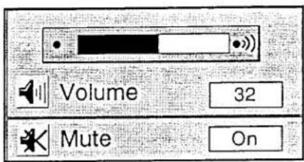
SOUND MUTE FUNCTION
Pressing the MUTE button on the remote control unit will mute audio. Press the MUTE button again to restore audio to its previous level. The mute display will be displayed on the screen for a few seconds.
ZOOM ADJUSTMENT
Press the ZOOM button (located on remote control unit or on the projector) and press POINT UP/DOWN button(s) to obtain your desired picture size. The Zoom display will be displayed on the screen for a few seconds.
For a larger picture, press (UP) and for a smaller picture, press (DOWN).
FOCUS ADJUSTMENT
Press the FOCUS button (located on remote control unit or on the projector) and press POINT UP/DOWN button(s) to obtain a sharper, crisper picture. The Focus display will be displayed on the screen for a few seconds.
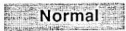
NORMAL PICTURE FUNCTION
The normal picture level is factory preset on the projector and can be restored anytime by pressing the NORMAL button (located on remote control unit or on the projector). The "Normal" display will be displayed on the screen for a few seconds.
FREEZE PICTURE FUNCTION
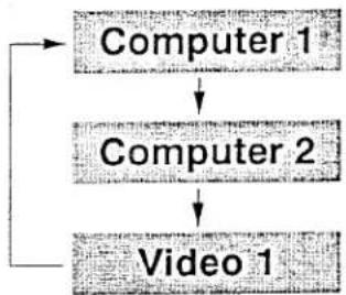
flowchart
graph TD
    A["Computer 1"] --> B["Computer 2"]
    B --> C["Video 1"]
Press the FREEZE button on the remote control unit, and the still picture will remain on-screen. This function is cancelled when the FREEZE button is pressed again or any other function button is pressed.
NOTE: Your computer or video equipment is not affected by this function, and will continue to run.
FINE SYNC ADJUSTMENT
Press the FINE SYNC (+) or (-) buttons (located on remote control unit or on the projector) to eliminate flicker from the display on computer mode. The Fine sync display will be displayed on the screen. Press the MENU button (located on remote control unit or on the projector). The Fine sync displays will disappear.
NOTE: The projector may not reproduce a proper image for some SXGA signals. Since SXGA (1280 × 1024) image is converted to XGA (1024 × 768) image by partial scan, some lines and dots of the image do not appear. Some video noise of flicker on this compressed SXGA image cannot be eliminated even though you try to make a FINE SYNC adjustment.
MENU OPERATION
In MENU OPERATION mode, you display menus where you can adjust the projector's settings. You can use the TOP CONTROL OF THE PROJECTOR or the REMOTE CONTROL UNIT.
You can select a mode used in the MENU among computer 1, computer 2 and video 1.
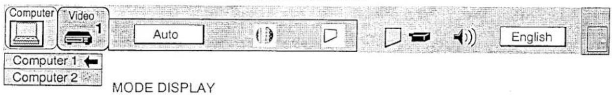
- Press the MENU BUTTON and the MAIN MENU DISPLAY dialog box will appear.
- Press the POINT LEFT/RIGHT BUTTON(s) to select Computer or Video and press the SELECT (REAR CLICK) BUTTON. Another dialog box MODE DISPLAY will appear.
- Press the POINT DOWN BUTTON and red arrow will appear.
- Move the arrow to the mode you want (computer 1, computer 2 or video 1) to use by pressing the POINT UP/DOWN BUTTON(s) and then press the SELECT (REAR CLICK) BUTTON.
MAIN MENU DISPLAY
MAIN MENU DISPLAY
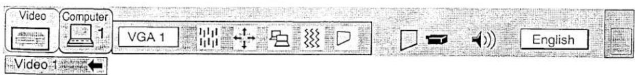
MODE DISPLAY
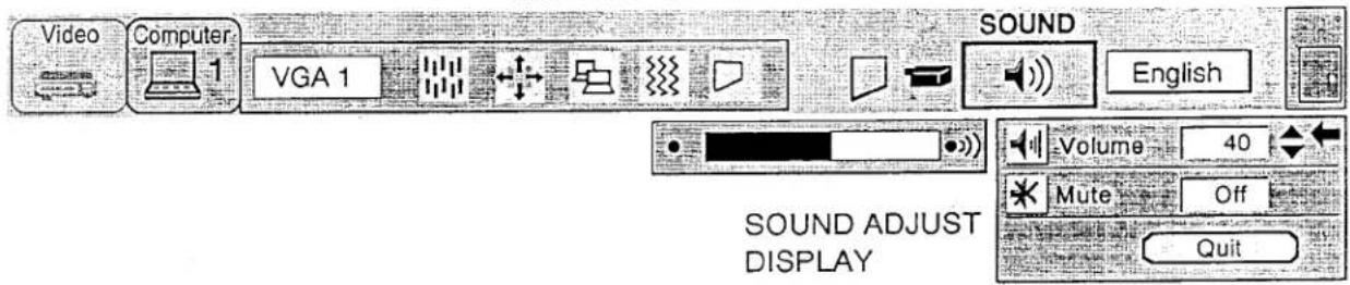
SOUND ADJUSTMENT
You can adjust the sound volume and sound mute used in the MENU.
- Press the MENU BUTTON and the MAIN MENU DISPLAY dialog box will appear.
- Press the POINT LEFT/RIGHT BUTTON(s) to select SOUND and press the SELECT (REAR CLICK) BUTTON. Another dialog box SOUND ADJUST DISPLAY will appear.
- Press the POINT DOWN BUTTON and red arrow will appear.
- Move the arrow to an item that you want you adjust by pressing the POINT UP/DOWN BUTTON(s).
- To increase the sound volume, point the arrow to △ and then press the SELECT (REAR CLICK) BUTTON. To decrease the sound volume, point the arrow to ▽ and then press the SELECT (REAR CLICK) BUTTON.
- To mute the sound, point the arrow to Mute and then press the SELECT (REAR CLICK) BUTTON. The mute display is changed On from Off and sound to mute.
- To quit the MENU, point to Quit and then press the SELECT (REAR CLICK) BUTTON.
MAIN MENU DISPLAY
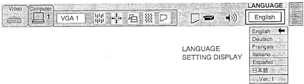
LANGUAGE ADJUSTMENT
You can select a language used in the MENU among English, German, French, Italian, Spanish and Japanese.
- Press the MENU BUTTON and the MAIN MENU DISPLAY dialog box will appear.
- Press the POINT LEFT/RIGHT BUTTON(s) to select LANGUAGE and press the SELECT (REAR CLICK) BUTTON. Another dialog box LANGUAGE SETTING DISPLAY will appear.
- Press the POINT DOWN BUTTON and red arrow will appear.
- Move the arrow to the language you want to use by pressing the POINT UP/DOWN BUTTON(s) and then press the SELECT (REAR CLICK) BUTTON.
- The setting is permanently held even if the MAIN ON/OFF is switched off.
MAIN MENU DISPLAY
MENU EXIT
When while in MENU mode, press the POINT RIGHT BUTTON to select right end ICON and press the SELECT (REAR CLICK) BUTTON. The menus will disappear and the MENU operation will end.
NOTE: When while in MENU mode, press again the MENU BUTTON. The menus will disappear and the MENU operation will end.
MAIN MENU DISPLAY

MENU EXIT ICON
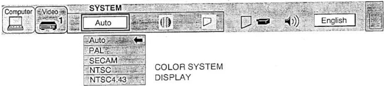
COLOR SYSTEM SELECT (VIDEO MODE)
This projector is compatible with the four major broadcast video standards: PAL, SECAM, NTSC or NTSC 4.43 (COLOR SYSTEMs). It automatically adjusts to optimize its performance for the incoming video. However, if the video signal is not strong enough to detect the video format, the projector may not reproduce the proper video image. In case this happens, this projector allows you to choose a specific broadcast signal format.
- Connect the video equipment and the PROJECTOR, and turn them on.
- Set MODE SELECT to "VIDEO MODE".
- Press the MENU BUTTON and the MAIN MENU DISPLAY dialog box will appear.
- Press the POINT LEFT/RIGHT BUTTON(s) to select SYSTEM and press the SELECT (REAR CLICK) BUTTON. Another dialog box COLOR SYSTEM DISPLAY will appear. The current COLOR SYSTEM is displayed in the system window.
- Press the POINT DOWN BUTTON and red arrow will appear.
- If you want to change the COLOR SYSTEM from the current one, move the arrow by press the POINT UP/DOWN BUTTON(s) to the system that you want to select and then press the SELECT (REAR CLICK) BUTTON and changed the color mode.
- The setting changed is temporarily effective until you turn off the MAIN ON/OFF switch.
MAIN MENU DISPLAY
SIMPLE METHOD
- Press the SYSTEM BUTTON. COLOR SYSTEM DISPLAY dialog box will appear.
- Press the POINT DOWN BUTTON and red arrow will appear.
- If you want to change the COLOR SYSTEM from the current one, move the arrow by press the POINT UP/DOWN BUTTON(s) to the system that you want to select and then press the SELECT (REAR CLICK) BUTTON and changed the color mode.
PICTURE IMAGE ADJUSTMENT (VIDEO MODE)
Although picture adjustments have been preset at the factory to our standards, you may want to change the setting.
- Press the MENU BUTTON and the MAIN MENU DISPLAY dialog box will appear.
- PRESS the MERC BUTTON and the MERC BUTTON to select IMAGE and press the SELECT (REAR CLICK) BUTTON.
- Press the POINT LEFT/RIGHT BUTTON(s) to select IMAGE and display settings. This shows how IMAGE ADJUST DISPLAY will appear. This shows the current picture settings.
Another dialog box IMAGE ADJUST DISPLAY will appear. This shows the current image of a dialog box with an additional adjustment to its effects by increasing or decreasing the levels shown as numbers. The items - In this dialog box, you can adjust the settings by increasing or decreasing the levels of
and the range of the levels that you can adjust are summarized in the table as below. - Press the POINT DOWN BUTTON and red arrow will appear.
- Move the arrow to an item that you want to adjust by pressing the POINT UP/DOWN BUTTON(s).
- Move the arrow to an item that you want to adjust by pointing to the arrow to a and then press the SELECT (REAR CLICK) BUTTON. To decrease the
- To increase the level, point the arrow to △ and then press the CELEOT (REAR CLICK BUTTON)
level. point the arrow to ▽ and then press the SELECT (REAR CLICK) BUTTON. - You may want to store the settings to the memory so that you can recall them later. To store the settings, move
You may want to store the following:
the arrow to Stored and then press the SELECT (REAR CLICK) BUTTON. When you have stored the settings,
the arrow to stored and then press the OZEEC (NE W. 2017).
you will see "OK?" as a confirmation. - Move the arrow to Yes and then press the SELECT (REAR CLICK) BUTTON. The stored settings are
permanently held even if the MAIN ON/OFF is switched off.
E. This MENU moves the arrow to Quit and then press the SELECT (REAR CLICK) BUTTON. - To quit the MENU, move the arrow to Quit and then press the SELECT (REAR CLICK)
- If you do not want to store the settings, move the arrow to Quit and then press the keyboard.
BUTTON. The settings changed are temporarily effective until you turn on the MAIN ON/OFF switch. - To recall the settings from the memory that you have stored, move the arrow to Reset and then press the
SELECT (REAR CLICK) BUTTON. When you have reset the settings, you will see "OK?" as a confirmation.
SELECT (REAR CLICK) BUTTON. When you have a button, you can adjust the settings again
Move the arrow to Yes and then press the SELECT (HEAVSLEY) but not a result.
if needed.
NOTE: "TINT" will be skipped during in the PAL and SECAM mode.
MAIN MENU DISPLAY
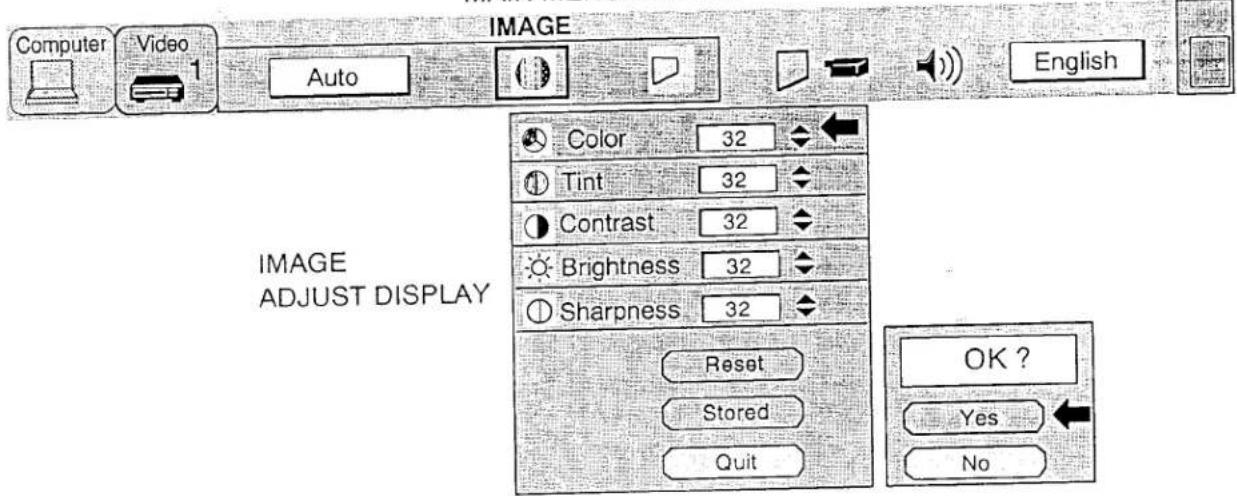
TABLE OF PICTURE IMAGE ADJUSTMENT
| COLOR | DECREASES | 0←→63 | INCREASES |
| TINT | MORE PURPLE | 0←→63 | MORE GREEN |
| CONTRAST | LIGHTER | 0←→63 | DEEPER |
| BRIGHTNESS | DARKER | 0←→63 | BRIGHTER |
| SHARPNESS | SOFTER | 0←→63 | SHARPER |
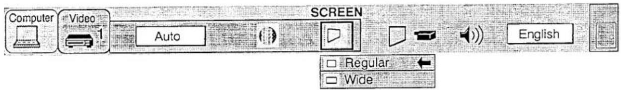
FIGURE SCREEN ADJOCOMENT [VIDEO MODE]
This projector has a Wide function, which enables you to view a wider video image.
WIDE function
This projector is designed to project a normal video image (with 4 x 3 aspect ratio). In addition, with the WIDE function, the projector can project a wider video image by compressing 4 x 3 image. This feature may be used by those who want to enjoy watching a movie with a cinema-like image. You can switch to either WIDE or REGULAR screen mode.
- Press the MENU BUTTON and the MAIN MENU DISPLAY dialog box will appear.
- Press the POINT LEFT/RIGHT BUTTON(s) to select SCREEN and press the SELECT (REAR CLICK) BUTTON. Another dialog box SCREEN ADJUST DISPLAY will appear.
- Press the POINT DOWN BUTTON and red arrow will appear.
- To switch to "Wide" mode, move the arrow to Wide by pressing the POINT UP/DOWN BUTTON(s) and then press the SELECT (REAR CLICK) BUTTON.
- To switch to "Regular" mode, move the arrow to Regular by pressing the POINT UP/DOWN BUTTON(s) and then press the SELECT (REAR CLICK) BUTTON.
- The "Wide" settings is temporarily effective until you turn off the MAIN ON/OFF switch.
MAIN MENU DISPLAY
SCREEN ADJUST DISPLAY
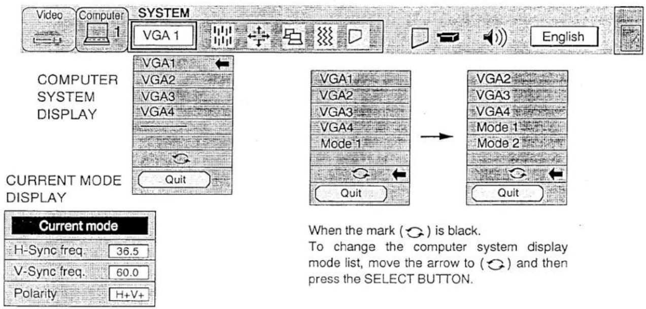
COMPUTER SYSTEM SELECT (COMPUTER MODE)
This projector is designed to adjust to different types of computer display signals based on VGA, SVGA, XGA or SXGA (See "COMPATIBLE COMPUTER SPECIFICATIONS" on the next page). If you set MODE SELECT to "COMPUTER", the projector will automatically process the incoming signal and project the proper image without any special setting. Although this will work in most cases, you may be required to manually set the projector for some computer signals. If the computer image is not reproduced properly, try the following procedure and switch to the computer display mode that you want to use.
- Connect the COMPUTER and the PROJECTOR, and turn them on.
- Set MODE SELECT to "COMPUTER MODE (1 or 2)". This shows the current display mode initially detected by the projector in the system window. And "Current mode" display appears.
NOTE: 1. If the projector cannot discriminate or detect the input signal from the computer, the "Go PC adj." display appears.
NOTE: 2. If no input signal from the computer, the "No signal" display appears on the screen.
- Press the MENU BUTTON and the MAIN MENU DISPLAY dialog box will appear.
- Press the POINT LEFT/RIGHT BUTTON(s) to select SYSTEM and press the SELECT (REAR CLICK) BUTTON. Another dialog box COMPUTER SYSTEM DISPLAY will appear.
- Press the POINT DOWN BUTTON and red arrow will appear.
- If you want to change the display mode from the current one, move the arrow by press the POINT UP/DOWN BUTTON(s) to select one of the modes.
- Press the SELECT (REAR CLICK) BUTTON and changed the display mode.
- To quit the MENU, move the arrow to Quit and then press the SELECT (REAR CLICK) BUTTON.
MAIN MENU DISPLAY
SIMPLE METHOD
- Press the SYSTEM BUTTON. COMPUTER SYSTEM DISPLAY dialog box will appear.
- Press the POINT DOWN BUTTON and red arrow will appear.
- If you want to change the display mode from the current one, move the arrow by press the POINT UP/DOWN BUTTON(s) to select one of the modes.
- Press the SELECT (REAR CLICK) BUTTON and changed the display mode.
- To quit the MENU, move the arrow to Quit and then press the SELECT (REAR CLICK) BUTTON.
PC ADJUSTMENT
This is a special function that may be used when a computer image is not reproduced properly. (See the pages 38 \~ 41 for more detail.)
COMPATIBLE COMPUTER SPECIFICATIONS
| ON-SCREEN DISPLAY | RESOLUTION | H-Freq. (kHz) | V-Freq. (Hz) | ON-SCREEN DISPLAY | RESOLUTION | H-Freq. (kHz) | V-Freq. (Hz) |
| VGA1 | 640 × 480 | 31.47 | 59.88 | XGA3 | 1024 × 768 | 60.08 | 75.10 |
| VGA2 | 720 × 400 | 31.47 | 70.09 | XGA4 | 1024 × 768 | 56.47 | 70.06 |
| VGA3 | 640 × 400 | 31.47 | 70.09 | XGA5 | 1024 × 768 | 60.31 | 74.92 |
| VGA4 | 640 × 480 | 37.86 | 74.38 | XGA6 | 1024 × 768 | 48.50 | 60.02 |
| VGA5 | 640 × 480 | 37.86 | 72.81 | XGA7 | 1024 × 768 | 44.00 | 54.58 |
| VGA6 | 640 × 480 | 31.70 | 61.91 | XGA8 | 1024 × 768 | 63.48 | 79.35 |
| MAC LC13 | 640 × 480 | 34.97 | 66.60 | XGA9 | 1024 × 768 | 36.00 | 87.17 |
| MAC 13 | 640 × 480 | 35.00 | 66.67 | MAC19 | 1024 × 768 | 60.24 | 75.08 |
| PC98 | 640 × 400 | 24.83 | 56.42 | SXGA1 | 1152 × 864 | 64.20 | 70.40 |
| FM TOWNS | 640 × 400 | 24.38 | 55.40 | SXGA2 | 1280 × 1024 | 62.50 | 58.60 |
| SVGA1 | 800 × 600 | 35.21 | 56.33 | SXGA3 | 1280 × 1024 | 63.98 | 60.02 |
| SVGA2 | 800 × 600 | 37.88 | 60.32 | SXGA4 | 1280 × 1024 | 63.34 | 59.98 |
| SVGA3 | 800 × 600 | 46.92 | 75.08 | SXGA5 | 1280 × 1024 | 63.74 | 60.01 |
| SVGA4 | 800 × 600 | 48.32 | 76.33 | SXGA6 | 1280 × 1024 | 71.57 | 67.20 |
| SVGA5 | 800 × 600 | 48.01 | 71.98 | SXGA7 | 1280 × 1024 | 81.12 | 75.99 |
| SVGA6 | 800 × 600 | 37.90 | 61.03 | SXGA8 | 1280 × 1024 | 81.18 | 75.99 |
| SVGA7 | 800 × 600 | 34.50 | 55.38 | SXGA9 | 1280 × 1024 | 81.97 | 76.00 |
| SVGA8 | 800 × 600 | 38.00 | 60.51 | SXGA10 | 1280 × 1024 | 81.25 | 76.00 |
| SVGA9 | 800 × 600 | 38.60 | 60.31 | SXGA11 | 1152 × 900 | 61.78 | 66.13 |
| SVGA10 | 800 × 600 | 47.90 | 71.92 | SXGA12 | 1152 × 900 | 71.73 | 76.21 |
| SVGA11 | 800 × 600 | 32.70 | 51.09 | SXGA13 | 1280 × 1024 | 50.00 | 86.00 |
| SVGA12 | 800 × 600 | 38.00 | 60.51 | SXGA14 | 1280 × 1024 | 50.00 | 94.00 |
| MAC 16 | 832 × 624 | 49.72 | 74.55 | MAC21 | 1152 × 870 | 68.68 | 75.06 |
| XGA1 | 1024 × 768 | 48.36 | 60.00 | MAC | 1280 × 960 | 75.08 | 75.08 |
| XGA2 | 1024 × 768 | 56.28 | 70.26 | MAC | 1280 × 1024 | 80.00 | 75.08 |
Specifications are subject to change without notice.
NOTE: The frequencies of some computers may not allow the image to be displayed correctly.
PICTURE IMAGE ADJUSTMENT (COMPUTER MODE)
Although picture adjustments have been preset at the factory to our standards, you may want to change the setting.
- Press the MENU BUTTON and the MAIN MENU DISPLAY dialog box will appear.
- Press the MENU BUTTON and the MAIN MENU button.
- Pass the POINT LEFT/RIGHT BUTTON(s) to select IMAGE and press the SELECT (REAR CLICK) BUTTON.
- Press the POINT LEFT/RIGHT BUTTON(S) to select IM/AD and PC
the position is also how IMAGE ADJUST DISPLAY will appear. This shows the current picture settings.
Another dialog box IMAGE ADJUST DISPLAY will appear. This shows the object that the settings are called at the settings by increasing or decreasing the levels shown as numbers. The items - In this dialog box, you can adjust the settings by increasing or decreasing the levels of and the range of the levels that you can adjust are summarized in the table as bellow.
- Press the POINT DOWN BUTTON and red arrow will appear.
- Move the arrow to an item that you want to adjust by pressing the POINT UP/DOWN BUTTON(s).
- Move the arrow to an item that you want to adjust, please call to you.
- The increase the level point the arrow to △ and then press the SELECT (REAR CLICK) BUTTON. To decrease the
- To increase the level, point the arrow to △ and then press the SELECT (REAR CLICK) button. level, point the arrow to ▽ and then press the SELECT (REAR CLICK) BUTTON.
- You may want to store the settings to the memory so that you can recall them later. To store the settings, move the arrow to Stored and then press the SELECT (REAR CLICK) BUTTON. When you have stored the settings, you will see "OK?" as a confirmation.
- Move the arrow to Yes and then press the SELECT (REAR CLICK) BUTTON. The stored settings are permanently held even if the MAIN ON/OFF is switched off.
- To quit the MENLL move the arrow to Quit and then press the SELECT (REAR CLICK) BUTTON.
- To quit the MENU, move the arrow to Quit and then press the SELECT (REAR CLICK)
- If you do not want to store the settings, move the arrow to quit and then press it.
- To recall the settings from the memory that you have stored, move the arrow to Reset and then press the SELECT (REAR CLICK) BUTTON. When you have reset the settings, you will see "OK?" as a confirmation. Move the arrow to Yes and then press the SELECT (REAR CLICK) BUTTON. You can adjust the settings again if needed.
MAIN MENU DISPLAY
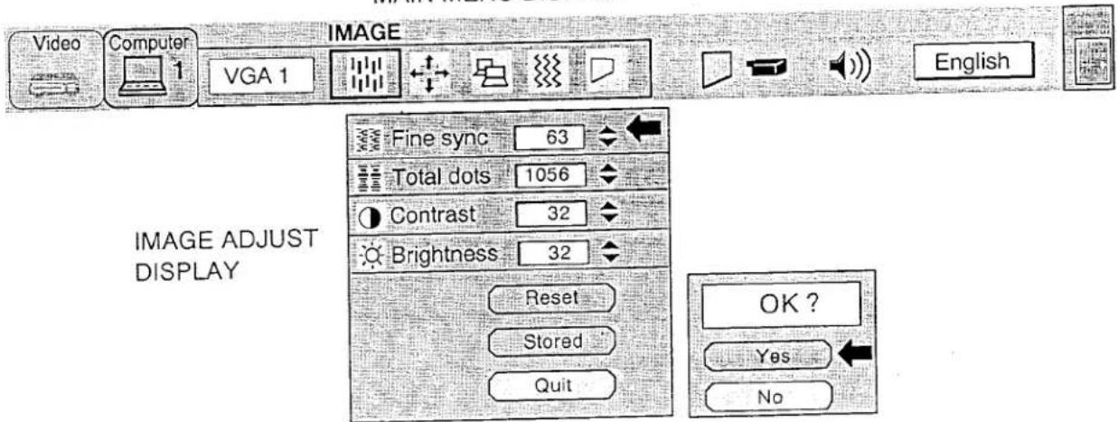
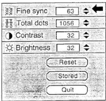
TABLE OF PICTURE IMAGE ADJUSTMENT
| FINE SYNC | Adjust the picture as necessary to eliminate flicker from the display. 0 ↔ 127 |
| TOTAL DOTS | The number of the total dots in one horizontal period. Adjust the number to match your PC image. |
| CONTRAST | LIGHTER 0 ↔ 63 DEEPER |
| BRIGHTNESS | DARKER 0 ↔ 63 BRIGHTER |
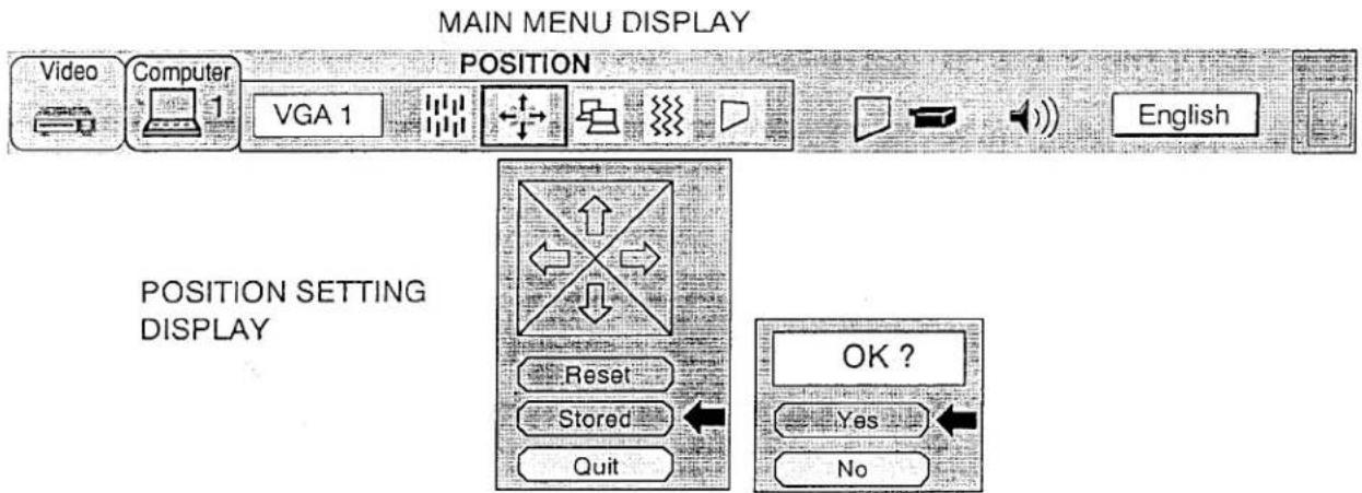
TICKLE POSITION ADJUSTMENT (COMPTER MODE)
- Press the MENU BUTTON and the MAIN MENU DISPLAY dialog box will appear.
-
Press the POINT LEFT/RIGHT BUTTON(s) to select POSITION and press the SELECT (REAR CLICK) BUTTON. Another dialog box POSITION SETTING DISPLAY will appear.
-
Press the POINT DOWN BUTTON and red arrow will appear.
-
Move the arrow to a direction (←, →, ↑ or ↓) by press the POINT LEFT/RIGHT/UP/DOWN BUTTON(s) and press the SELECT (REAR CLICK) BUTTON to you want picture position.
-
You may want to store the settings to the memory so that you can recall them later. To store the settings, move the arrow to Stored and then press the SELECT (REAR CLICK) BUTTON. When you have stored the settings, you will see "OK?" as a confirmation.
-
Move the arrow to Yes and then press the SELECT (REAR CLICK) BUTTON. The stored settings are permanently held even if the MAIN ON/OFF is switched off.
-
To quit the MENU, move the arrow to Quit and then press the SELECT (REAR CLICK) BUTTON.
-
If you do not want to store the settings, move the arrow to Quit and then press the SELECT (REAR CLICK) BUTTON. The settings changed are temporarily effective until you turn off the MAIN ON/OFF switch.
-
To recall the settings from the memory that you have stored, move the arrow to Reset and then press the SELECT (REAR CLICK) BUTTON. When you have reset the settings, you will see "OK?" as a confirmation. Move the arrow to Yes and then press the SELECT (REAR CLICK) BUTTON. You can adjust the settings again if needed.
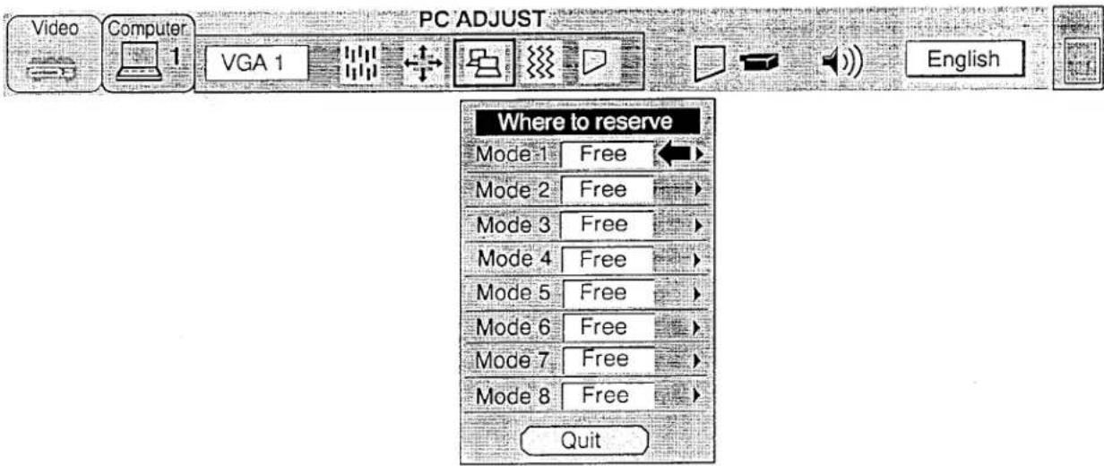
PC ADJUSTMENT
This projector can automatically detect most display signals in most personal computers currently distributed. However, some computers employ a special signal format which is different from the standard ones and may not be detected by this projector. If this happens, the projector cannot reproduce a proper image, often recognized as a flickering picture, a non-synchronized picture, a non-centered picture or a skewed picture.
To project a proper image for those non-standard formats, this projector provides PC ADJUST, in which you can precisely adjust several parameters to match the input signal format. The projector has eight independent memory areas that you can store the parameter settings you have made. Therefore, you can recall the setting for a specific computer when you need it.
- Press the MENU BUTTON and the MAIN MENU DISPLAY dialog box will appear.
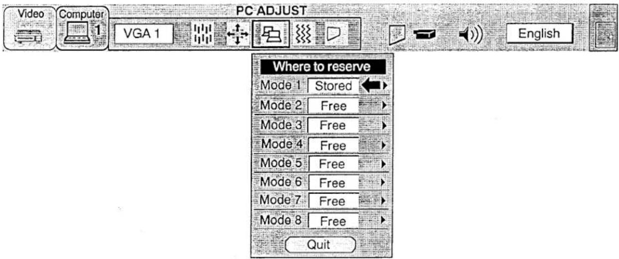
- Press the POINT LEFT/RIGHT BUTTON(s) to select PC ADJUST and press the SELECT (REAR CLICK) BUTTON. Another dialog box "Where to reserve" will appear.
- In this dialog box, you will select one of the memory areas shown as "Mode 1" to "Mode 8". If the parameters have been previously set and stored to the memory, the status "Stored" will appear on a corresponding row. If not, "Free" will appear.
- Press the POINT DOWN BUTTON and red arrow will appear.
- Move the arrow to one of the "Modes" (Free position) that you want to store by pressing the POINT UP/DOWN BUTTON(s). Press the SELECT (REAR CLICK) BUTTON to select it.
NOTE; If all Modes is Stored will appear, cannot stored the new PC parameter data. In this case, you must be cleared the PC parameter data used the Mode free Function.
MAIN MENU DISPLAY
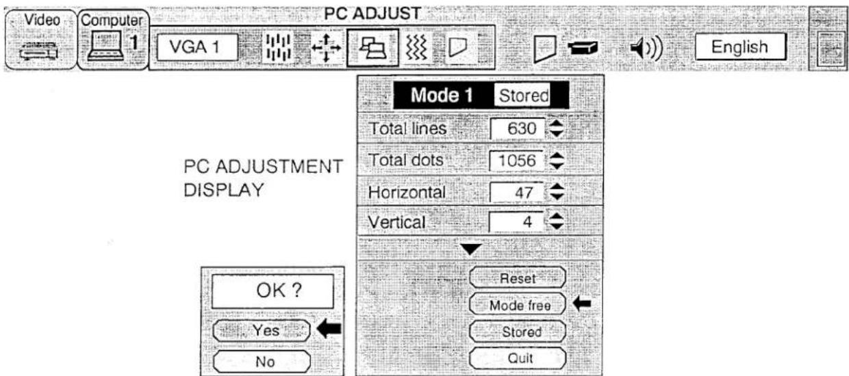
- Another dialog box "PC ADJUSTMENT DISPLAY" will appear and the parameter data for the mode you have selected is shown in this dialog box.
- The parameters will be filled with the data determined by the projector according to the present signal input.
- The function of the parameters and their values are summarized in the table as bellow.
- Move the arrow to an item that you want to adjust by pressing the POINT UP/DOWN BUTTON(s).
- To increase the level, point the arrow to and then press the SELECT (REAR CLICK) BUTTON. To decrease the level, point the arrow to and then press the SELECT (REAR CLICK) BUTTON.
- If you want to store the settings to the memory, move the arrow to Stored and press the SELECT (REAR CLICK) BUTTON. When you have stored the settings, you will see "OK?" as a confirmation. Move the arrow to Yes and then press the SELECT (REAR CLICK) BUTTON.
- To recall the parameter data before setting, move the arrow to Reset and then press the SELECT (REAR CLICK) BUTTON. When you have reset the settings, you will see "OK?" as a confirmation. Move the arrow to Yes and then press the SELECT (REAR CLICK) BUTTON. You can adjust the settings again if needed.
- To quit the MENU, move the arrow to Quit and then press the SELECT (REAR CLICK) BUTTON.
- If you quit the MENU without storing the settings to the memory, the parameter data you changed will not be kept.
- The stored settings are permanently held even if the MAIN ON/OFF is switched off.
- Adjust the data such as a "Clamp", "Height" and "Width" if you needed, move the arrow by pressing the POINT UP/DOWN BUTTON(s) to select (▼). Press the SELECT (REAR CLICK) BUTTON.
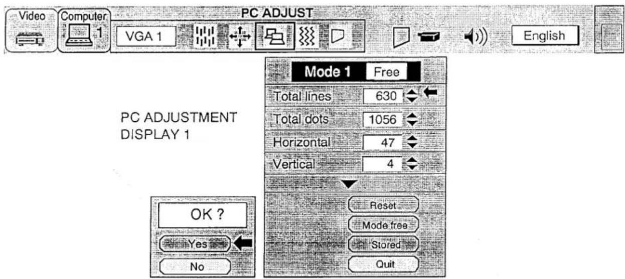
| ITEM | FUNCTION |
| TOTAL LINES | The number of the total vertical lines. Adjust the number to match your PC image. |
| TOTAL DOTS | The number of the total dots in one horizontal period. Adjust the number to match your PC image. |
| HORIZONTAL | Adjustment of the horizontal picture position. When the image is not centered on the screen, adjust this. |
| VERTICAL | Adjustment of the vertical picture position. When the image is not centered on the screen, adjust this. |
- Another dialog box "PC ADJUSTMENT DISPLAY 2" will appear and the parameter data for the Mode you have selected is shown in this dialog box.
- Move the arrow to an item that you want to adjust by pressing the POINT UP/DOWN BUTTON(s).
- To increase the level, point the arrow to △ and then press the SELECT (REAR CLICK) BUTTON. To decrease the level, point the arrow to ▽ and then press the SELECT (REAR CLICK) BUTTON.
- If you want to store the settings to the memory, move the arrow to Stored and press the SELECT (REAR CLICK) BUTTON. When you have stored the settings, you will see "OK?" as a confirmation. Move the arrow to Yes and then press the SELECT (REAR CLICK) BUTTON.
- To recall the parameter data before settings, move the arrow to Reset and then press the SELECT (REAR CLICK) BUTTON. When you have reset the settings, you will see "OK?" as a confirmation. Move the arrow to Yes and then press the SELECT (REAR CLICK) BUTTON. You can adjust the settings again if needed.
- To quit the MENU, move the arrow to Quit and then press the SELECT (REAR CLICK) BUTTON.
- If you quit the MENU without storing the settings to the memory, the parameter data you changed will not be kept.
- The stored settings are permanently held even if the MAIN ON/OFF is switched off.
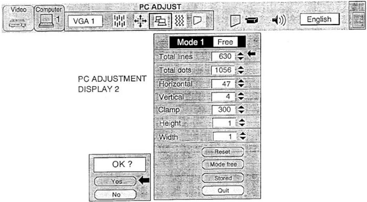
| ITEM | FUNCTION |
| CLAMP | Adjustment of the clamp level. When the image has a dark bar, try this adjustment. |
| HEIGHT | Expanding or compressing level for the vertical direction. |
| WIDTH | Expanding or compressing level for the horizontal direction. |
MODE FREE
The Mode free function is designed to confirm or clear the parameter data produced by PC ADJUST.
- Press the MENU BUTTON and the MAIN MENU DISPLAY dialog box will appear.
- Press the POINT LEFT/RIGHT BUTTON(s) to select PC ADJUST and press the SELECT (REAR CLICK) BUTTON. Another dialog box "Where to reserve" will appear.
Press the POINT DOWN BUTTON and red arrow will appear.
i. Move the arrow to one of the "Modes" (Stored position) that you want to confirm by pressing the POINT UP/DOWN BUTTON(s). Press the SELECT (REAR CLICK) BUTTON. Another dialog box "PC ADJUSTMENT DISPLAY" will appear. - To quit the MENU, point to Quit and then press the SELECT (REAR CLICK) BUTTON.
- If you modify the parameter data, effect the steps 9 \~ 24 of PC ADJUSTMENT SECTION.
- If you clear the parameter data, move the arrow by pressing the POINT UP/DOWN BUTTON(s) to select Mode free. Press the SELECT (REAR CLICK) BUTTON. You will see "OK?" as a confirmation.
- Move the arrow to Yes and then press the SELECT (REAR CLICK) BUTTON, the parameter data is clear.
- To quit the MENU, move the arrow to Quit and then press the SELECT (REAR CLICK) BUTTON.
MAIN MENU DISPLAY
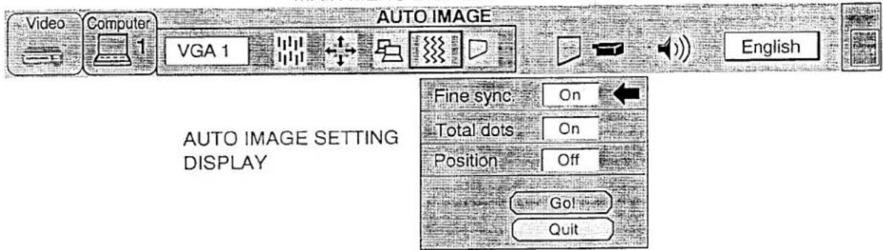
AUTO IMAGE FUNCTION (COMPUTER MODE)
The Auto image function is designed automatically adjusts Fine sync., Total dots and Screen position for most computers.
- Press the MENU BUTTON and the MAIN MENU DISPLAY dialog box will appear.
- Press the POINT LEFT/RIGHT, BUTTON(s) to select AUTO IMAGE and press the SELECT (REAR CLICK) BUTTON. Another dialog box AUTO IMAGE SETTING DISPLAY will appear.
- Press the POINT DOWN BUTTON and red arrow will appear.
- Move the arrow to an item(s) you want to be adjust by pressing the POINT UP/DOWN BUTTON(s).
- Change the setting "On", press the SELECT (REAR CLICK) BUTTON.
- Move the arrow by pressing the POINT UP/DOWN BUTTON(s) to select Go! and then press the SELECT (REAR CLICK) BUTTON. The auto image function is started now. It will take at 10 \~ 60 seconds.
- To quit the MENU, point to Quit and then press the SELECT (REAR CLICK) BUTTON.
- This setting is temporarily effective until you turn off the projector or changed the input signal.
MAIN MENU DISPLAY
This projector has a picture screen resize function, which enables you to project the image size.
| Input image resolution | True Mode | Expand Mode | Compressed Mode | Panning Mode |
| Less than XGA (1024 × 768) image |  |  | None | None |
| XGA (1024 × 768) image | 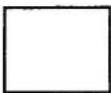 | None | None | None |
| More than XGA (1024 × 768) image | None | None | 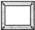 | 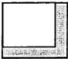 |
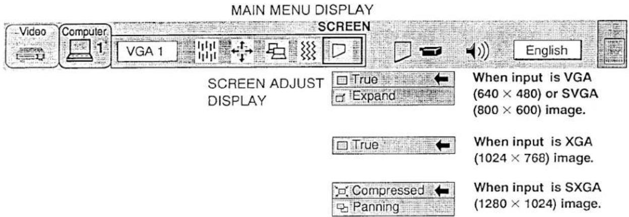
- Press the MENU BUTTON and the MAIN MENU DISPLAY dialog box will appear.
- Press the POINT LEFT/RIGHT BUTTON(s) to select SCREEN and press the SELECT (REAR CLICK) BUTTON. Another dialog box SCREEN ADJUST DISPLAY will appear.
- Press the POINT DOWN BUTTON and red arrow will appear.
- To switch to "Expand mode", move the arrow to Expand by pressing the POINT UP/DOWN BUTTON(s) and then press the SELECT (REAR CLICK) BUTTON. The mode is changed "Expand".
- To switch to "True mode", move the arrow to True by pressing the POINT UP/DOWN BUTTON(s) and then press the SELECT (REAR CLICK) BUTTON. The mode is changed "True".
- To switch to "Compressed mode", move the arrow to Compressed by pressing the POINT UP/DOWN BUTTON(s) and then press the SELECT (REAR CLICK) BUTTON. The mode is changed "Compressed".
- To switch to "Panning mode", move the arrow to Panning by pressing the POINT UP/DOWN BUTTON(s) and then press the SELECT (REAR CLICK) BUTTON. The mode is changed "Panning". Panning the image position, by pressing the POINT UP/DOWN/LEFT/RIGHT BUTTON(s). And then press the SELECT (REAR CLICK) BUTTON.
- This setting is temporarily effective until you turn off the MAIN ON/OFF switch.
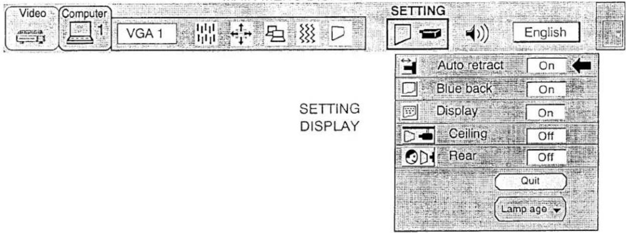
OTHER FUNCTION SETTING
This projector has other function settings; Auto retract, Blue back, Display, Ceiling, Rear and Lamp age.
AUTO RETRACT
When this function is in the "On" position, the projector retracts the lens when the projector is turned off using the LAMP POWER ON/OFF button. To protect the lens from being damaged while you are carrying the projector, you are strongly recommended to set this function "On". Since the lens is pulled in each time the POWER is switched off, you need to make ZOOM and FOCUS adjustments when you turn on the projector.
BLUE BACK
When this function is in the "On" position, the projector will project a blue image without video noise on the screen when the video source is unplugged or turned off.
DISPLAY
When this function is in the "On" position, on-screen displays always appear when adjustments are made. Although these on-screen displays are very helpful, these may spoil the view if adjustments are made during presentations. To avoid this, you can keep back certain displays by switching this function "Off". The followings are the displays that you can hide.
- Wait Display
• Volume Display - Mute Display
- Normal Display
CEILING
When this function is in the "On" position, the top/bottom and the left/right picture reverse capability lets you project from a ceiling-mounted projector.
REAR
When this function is in the "On" position, the left/right picture reverse capability lets you project onto a rear projection screen.
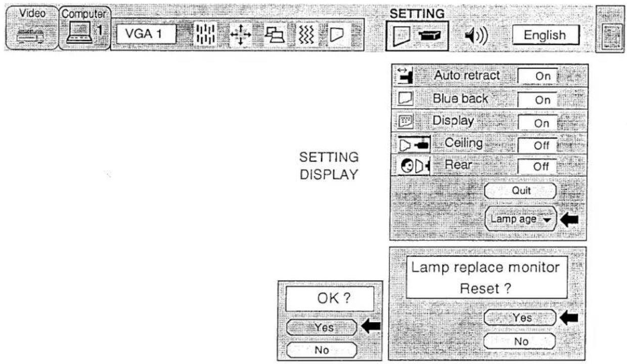
LAMP AGE
The Lamp age function is designed to reset the lamp replacement monitor timer. When replace the lamp, reset the lamp replacement monitor timer for used this function.
- Press the MENU BUTTON and the MAIN MENU DISPLAY dialog box will appear.
- Press the POINT LEFT/RIGHT BUTTON(s) to select SETTING and press the SELECT (REAR CLICK) BUTTON. Another dialog box SETTING DISPLAY will appear.
- Press the POINT DOWN BUTTON and red arrow will appear.
- Move the arrow to an item you want to be adjust by pressing the POINT UP/DOWN BUTTON(s).
- If you want to change the setting (On or Off), press the SELECT (REAR CLICK) BUTTON.
- To quit the MENU, point to Quit and then press the SELECT (REAR CLICK) BUTTON.
- The settings are permanently kept even if the MAIN ON/OFF is switched off.
MAIN MENU DISPLAY
LAMP AGE
NOTE: Do not reset the LAMP REPLACEMENT MONITOR TIMER, except after the lamp replacement.
- Press the MENU BUTTON and the MAIN MENU DISPLAY dialog box will appear.
- Press the POINT LEFT/RIGHT BUTTON(s) to select SETTING and press the SELECT (REAR CLICK) BUTTON. Another dialog box SETTING DISPLAY will appear.
- Press the POINT DOWN BUTTON and red arrow will appear.
- Move the arrow by pressing the POINT UP/DOWN BUTTON(s) to select Lamp age and then press the SELECT (REAR CLICK) BUTTON. When you reset the lamp replace monitor, you will see "lamp replace monitor reset?" as a confirmation.
- Move the arrow to Yes and then press the SELECT (REAR CLICK) BUTTON, you will see "OK?" as a confirmation. Move the arrow to Yes and then press the SELECT (REAR CLICK) BUTTON, the lamp replace monitor is reset.
- Move the arrow to No and then press the SELECT (REAR CLICK) BUTTON. The lamp replace monitor is not reset.
- To quit the MENU, move the arrow to Quit and then press the SELECT (REAR CLICK) BUTTON.
MAIN MENU DISPLAY
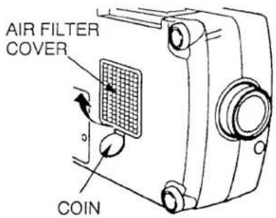
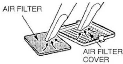
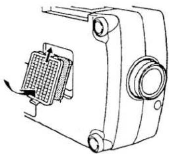
AIR FILTER CARE AND CLEANING
The removable air filter prevents dust from accumulating on the surface of the projection lens and projection mirror. Should the air filter become clogged with dust particles, it will reduce the cooling fan's effectiveness and may result in internal heat build up and reduce the life of the projector.
To clean the air filter, follow the cleaning procedures below:
- Turn the LAMP POWER ON/OFF button OFF.
- Remove the air filter cover.
Carefully place a coin against the indented part of the filter cover and lift.
- Remove the air filter from the filter cover.
- Clean the air filter with a vacuum cleaner.
- Replace the air filter. Make sure that air filter cover is fully inserted.

Do not clean with water. Doing so may damage the air filter. Do not operate the projector with air filter removed.
RECOMMENDATION
TO ENJOY PICTURE IMAGE, USE THE PROJECTOR IN THE CLEAN ENVIRONMENT. USAGE IN THE CLEAN ENVIRONMENT IS RECOMMENDED.
When used under the dusty or smoky conditions, dust may accumulate on the liquid crystal panel and lens inside it, and may resultantly be projected on the screen together with the picture.
When the above symptoms are noticed contact the place where your authorized dealer or service station for the cleaning.
natural_image
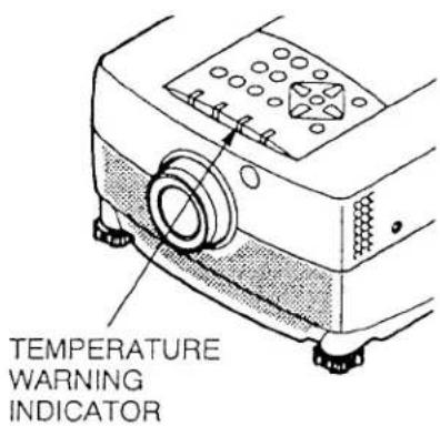
Technical line drawing of a mechanical device with a grid component and mounting bracket (no text or symbols)TEMPERATURE WARNING INDICATOR
The TEMPERATURE WARNING INDICATOR flashes red when the internal temperature of the projector exceeds the normal temperature.
Possible causes for the temperature warning may be:
- Ventilation slots of the projector are blocked. In such an event, reposition the projector so that ventilation slots are not obstructed.
- Air filter is clogged with dust particles. Remove dust from the air filter by following instructions in the Air Filter Care and Cleaning section above.
- If temperature warning indicator remains on after performing the checks listed above, cooling fan/internal circuits may be malfunctioning. Request service from an authorized dealer or service station.
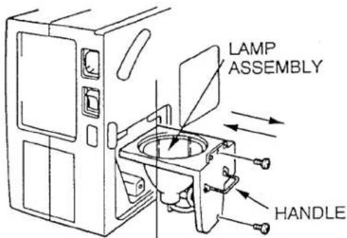
LAMP REPLACEMENT
If the lamp fails to come on and the lamp monitor on the projector light is orange, you must replace the bulb.

- For continued safety, replace with a lamp assembly of the same type.
- Allow the projector to cool for at least 45 minutes before you open the lamp cover. The inside of the projector can become very hot.
- Do not drop the lamp module or touch the glass bulb! The glass can shatter and cause injury.
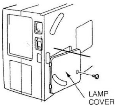
Follow these steps to replace the lamp assembly.
- Turn off the projector and allow the projector to cool thoroughly.
- Disconnect the AC cord from the projector.
- Remove screw with a screwdriver and disconnect the lamp cover.
- Remove 2 screws with a screwdriver and pull out the lamp assembly by grasping the handle.
- Replace the lamp assembly.
- Tighten 3 screws to secure the lamp cover to the lamp assembly.
- Connect the detachable AC cord to the projector.
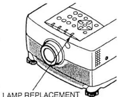
LAMP REPLACEMENT INDICATOR
- Reset the lamp replacement monitor timer. (See "LAMP AGE" section on page 46.)
NOTE: Do not reset the LAMP REPLACEMENT MONITOR TIMER, except after the lamp replacement.
CLEANING THE LENS
Follow these steps to clean the projection lens:
- Apply a non-abrasive camera lens cleaner to a soft, dry cleaning cloth.
Avoid using an excessive amount of cleaner.
Abrasive cleaners, solvents or other harsh chemicals might scratch the lens.
- Lightly wipe the cleaning cloth over the lens.
- If you don't intend to use the projector immediately, replace the lens cover.
TROUBLESHOOTING
Before calling your dealer or service station for assistance, follow these steps, in this order, to make sure everything is properly connected.
- Make sure you have connected the projector to your equipment as described in section "CONNECTING THE PROJECTOR" on pages 10 \~ 17.
- Check cable connections. Verify that all computer, video and power cord are properly connected.
- Verify that all power is switched on.
- If the projector still does not display an image, restart the computer.
- If the image still does not display, unplug the projector from the computer and check the computer monitor's display. The problem may be with your graphics controller rather than with the projector. (When you reconnect the projector, remember to turn the computer and monitor off before you power up the projector. Power the equipment back up in this order: Projector, monitor, computer)
- If the problem still exists, check the following chart.
| Problem: | Try these Solutions: |
| No power | Plug the projector into an AC outlet.Turn the MAINS ON/OFF button to ON.Press the LAMP POWER ON/OFF switch to ON.Be sure the READY INDICATOR light is ON.Wait one minute after the projector is turned OFF before turning the projector back on.NOTE: After pressing the LAMP POWER ON/OFF button to OFF. The projector functions as follows.The LAMP POWER indicator will light and the READY indicator will turn off.After one minute, the READY indicator will light green again and the projector may be turned on by pressing the LAMP POWER ON/OFF button.Check temperature warning indicator. If the indicator flashes red, the projector cannot be turned on.(See "USING THE PROJECTOR" section on page 27).Check the projection lamp. |
| Image is out of focus | Adjust the focus.Make sure the projection screen is at least 3.6 feet (1.1 m) from the projector.Check the projection lens to see if it needs cleaning.NOTE: Moving the projector from a cool temperature location to a warm temperature location may result in moisture condensation on the lens. In such an event, leave the projector OFF and wait until condensation disappears. |
| The lens is pulled in when the POWER is switched off. | Check AUTO RETRACT function.(See "OTHER FUNCTION SETTING" section on pages 44 ~ 45). |
| Picture is L/R Reversed. | Check Ceiling/Rear feature.(See "OTHER FUNCTION SETTING" section on pages 44 ~ 45). |
| Picture is T/B inverted. | Check Ceiling feature.(See "OTHER FUNCTION SETTING" section on pages 44 ~ 45). |
| Some displays are not seen during the operation. | Check Display feature.(See "OTHER FUNCTION SETTING" section on pages 44 ~ 45). |
| No sound. | Check audio cable connection from audio input source.Adjust audio source.Press the VOLUME (+) button.Press the MUTE button. |
| Remote control unit doesn't work. | Check the batteries.Make sure nothing is blocking the remote control unit on the projector.Make sure you are not too far from the projector when using the remote control unit. {Maximum operate range 16.4 feet (5 m)}. |
| Wireless mouse function does not work. | Check the cable connection between the projector and the computer.Check the mouse setting on your computer.Turn on the projector before you turn on the computer. |
SERVICE
WARNING: High voltages are used to operate this projector. Do not remove the back from your unit.
You can often correct operating problems yourself. If the projector fails to work properly, see "TROUBLESHOOTING" section on pages 49-50. To correct the failure, try the "Solutions."
Sanyo Service is easily obtained. If after following all operating instructions, you find that service is necessary, contact the SFS Corporation in Los Angeles, or the store where you purchased the unit. Give the model number and explain the difficulty. We will advise you how to obtain service.
TECHNICAL SPECIFICATIONS
SPECIFICATIONS
| Projector Type | Multi-media Projector |
| - mensions (W x H x D) | 10.2" (260 mm) × 6.3" (159 mm) × 15.4" (391 mm) |
| Net Weight | 13.0 lbs (5.9 kg) |
| LCD Panel System | 1.3" TFT Active Matrix type (Thin Film Transistor) × 3 |
| Number of Pixels | 2,359,296 {786,432 (1,024 × 768) × 3} |
| Color System | 4 color system (PAL, SECAM, NTSC and NTSC4.43) |
| Scanning Frequency | H-sync. 15 ~ 82 KHz, V-sync. 50 ~ 94 Hz |
| Projection Image Size (Diagonal) | Adjustable from 20" to 400" |
| Contrast Ratio | 100 :1 (ANSI) |
| Horizontal Resolution | 800 TV lines |
| Projection Lens | f2.5 ~ 3.2 lens with 1.77" ~ 2.95" Motor zoom and focus |
| Throw Distance | 3.6' (1.1 m) ~ 47' (14.3 m) |
| Projection Lamp | Metal Halide, 120 watt type |
| Projection Mirror | Dichroic mirror and X-prism system |
| AV Input Jacks | RCA Type × 1 (Video, Audio R and L)and DIN 4 pin (S-Video) × 1 |
| Computer Input Jack | (VGA) HDB15 Terminal × 2, Multi-pole 12 pin (Control port) × 2 |
| Monitor Output Jack | (VGA) HDB15 Terminal × 1 |
| Computer Audio Input Jack | Mini Stereo Type × 2 |
| 'ideo Monitor Output Jack | RCA Type × 1 |
| Audio Monitor Output Jacks | RCA Type × 1 (R and L) |
| Other Jacks | EXT. Speaker Jack × 1 |
| Built-In Speaker | INT. SP. Stereo (R and L), 2 watt RMS (T.H.D. 10%) |
| Image Elevation Adjustment | Up to 6° |
| Voltage | 100 ~ 120V AC, 50/60 Hz |
| Power Consumption | 2.0A (Max. Ampere) |
| Operating Temperature | 5°C ~ 35°C |
| Storage Temperature | -10°C ~ 60°C |
| Remote Control Battery | (2) AA Type |

This symbol on the nameplate means the product is Listed by Underwriters Laboratories Inc. It is designed and manufactured to meet rigid U.L. safety standards against risk of fire, casualty and electrical hazards.
SANYO INDUSTRIAL VIDEO LCD PROJECTOR LIMITED WARRANTY
OBLIGATIONS
In order to obtain warranty service, the product must be delivered to and picked up from an Authorized Sanyo Service Center at the user's expense, unless specifically stated otherwise in this warranty. The names and addresses of Authorized Sanyo Service Centers may be obtained by writing to SFS Corporation, SFC's warranty administrator, at any of the addresses listed below, or by calling (toil-free) 1-800-421-5013.
New Jersey Office
210 Riser Road
Little Ferry, NJ 07643
201-641-3000
California Office
1200 W. Artesia Blvd.
Compton, CA 90220
310-537-5830
Illinois Office
900 N. Arlington Heights Road
Itasca, IL 60143 U.S.A.
708-775-1414
THIS WARRANTY IS VALID ONLY ON SANYO PRODUCTS PURCHASED OR RENTED IN THE UNITED STATES OF AMERICA, EXCLUDING HAWAII AND ALL U.S. TERRITORIES AND PROTECTORATES. THIS WARRANTY APPLIES ONLY TO THE ORIGINAL RETAIL USER. THE ORIGINAL DATED BILL OF SALE, SALES SLIP OR RENTAL AGREEMENT MUST BE SUBMITTED TO THE AUTHORIZED SANYO SERVICE CENTER AT THE TIME WARRANTY SERVICE IS REQUESTED.
Subject to the OBLIGATIONS above and EXCLUSIONS below, SANYO FISHER (USA) COMPANY (SFC) warrants this SANYO product against defects in materials and workmanship for the periods specified below. SFC will repair or replace (at its option) the product and any of its parts which fail to conform to this warranty. The warranty period commences on the date the product was first purchased or rented at retail.
| LABOR | PARTS | LAMP |
| 1 YEAR | 1 YEAR | 90 DAYS |
EXCLUSIONS
This warranty does not cover (A) the adjustment of customer-operated controls as explained in the appropriate model's instruction manual, or (B) the repair of any product whose serial number has been altered, defaced or removed.
This warranty shall not apply to the cabinet or cosmetic parts, knobs or batteries.
This warranty does not apply to uncrating, setup, installation, removal of the product for repair or reinstallation of the product after repair.
This warranty does not apply to repairs or replacements necessitated by any cause beyond the control of SFC including, but not limited to, any malfunction, defect or failure caused by or resulting from unauthorized service or parts, improper maintenance, operation contrary to furnished instructions, shipping or transit accidents, modification or repair by the user, abuse, misuse, neglect, accident, incorrect power line voltage, fire, flood or other Acts of God, or normal wear and tear.
The foregoing is in lieu of all other expressed warranties and SFC does not assume or authorize any party to assume for it any other obligation or liability.
THE DURATION OF ANY WARRANTIES WHICH MAY BE IMPLIED BY LAW (INCLUDING THE WARRANTIES OF MERCHANTABILITY AND FITNESS) IS LIMITED TO THE TERM OF THIS WARRANTY. IN NO EVENT SHALL SFC BE LIABLE FOR SPECIAL, INCIDENTAL OR CONSEQUENTIAL DAMAGES ARISING FROM OWNERSHIP OR USE OF THIS PRODUCT, OR FOR ANY DELAY IN THE PERFORMANCE OF ITS OBLIGATIONS UNDER THIS WARRANTY DUE TO CAUSES BEYOND ITS CONTROL.
SOME STATES DO NOT ALLOW LIMITATIONS ON HOW LONG AN IMPLIED WARRANTY LASTS AND/OR DO NOT ALLOW THE EXCLUSION OR LIMITATION OF CONSEQUENTIAL DAMAGES, SO THE ABOVE LIMITATIONS AND EXCLUSIONS MAY NOT APPLY TO YOU.
THIS WARRANTY GIVES YOU SPECIFIC LEGAL RIGHTS. YOU MAY HAVE OTHER RIGHTS, WHICH VARY FROM STATE TO STATE.
ATTENTION
For your protection in the event of theft or loss of this product, please fill in the information below for your own personal records.
Model No. ____
Serial No. ____
(Located on back or bottom side of unit.)
Date of Purchase ____ Purchase Price ____
Where Purchased

21605 Plummer Street,
Chatsworth, California 91311
Printed in Japan
Part No. 610 267 8864 (1AA6P1P1252-- M6KA)
- SANYO
- Multimedia Projector
- INFORMATION TO THE USER
- TO THE OWNER
- SAFETY PRECAUTIONS
- WARNING:
- INTRODUCTION
- DMPATIBILITY
- IMAGE RESOLUTION
- PORTABILITY
- UNPACKING THE PROJECTOR
- TRADEMARKS
- POWER REQUIREMENTS
- FRONT
- REAR
- EXHAUST VENT
- CAUTION HOT AIR!
- BOTTOM
- SETTING-UP THE PROJECTOR
- POSITIONING:
- ROOM LIGHT
- VENTILATION
- LEVELING AND ELEVATING ADJUSTMENTS
- MOVING THE PROJECTOR
- CONNECTING THE PROJECTOR
- CONNECTING THE COMPUTER
- CONNECTING TO THE COMPUTER INPUT HDB15-PIN (VGA) TERMINALS (1 and 2)
- CONNECTING TO THE MONITOR OUTPUT HDB15-PIN (VGA) TERMINAL
- Pin No./Signal
- CONNECTING TO THE COMPUTER AUDIO INPUT JACKS (1 and 2)
- CONNECTING TO THE MULTI-POLE 12-PIN (CONTROL PORT) CONNECTORS (1 and 2)
- CONTROL PORT CABLE REMOVAL HINT
- CONNECTING THE VIDEO EQUIPMENT
- CONNECTING TO THE AV INPUT JACKS
- S-VHS FORMAT VCR CONNECTION
- CONNECTING TO THE VIDEO MONITOR OUTPUT JACK
- CONNECTING TO THE AUDIO MONITOR OUTPUT JACKS
- CONNECTING AN EXTERNAL SPEAKER
- REAR OF THE PROJECTOR
- OPERATION OF REMOTE CONTROL
- REMOTE CONTROL BATTERY INSTALLATION
- 1
- 2
- 3
- USING THE REMOTE CONTROL UNIT
- CONTROL THE PROJECTOR
- TO TURN ON THE PROJECTOR
- CAUTION:
- TO TURN OFF THE PROJECTOR
- DIRECT OPERATION
- MODE SELECT
- SOUND VOLUME ADJUSTMENT
- SOUND MUTE FUNCTION
- ZOOM ADJUSTMENT
- FOCUS ADJUSTMENT
- NORMAL PICTURE FUNCTION
- FREEZE PICTURE FUNCTION
- FINE SYNC ADJUSTMENT
- MENU OPERATION
- SOUND ADJUSTMENT
- LANGUAGE ADJUSTMENT
- MENU EXIT
- COLOR SYSTEM SELECT (VIDEO MODE)
- SIMPLE METHOD
- PICTURE IMAGE ADJUSTMENT (VIDEO MODE)
- FIGURE SCREEN ADJOCOMENT [VIDEO MODE]
- WIDE function
- COMPUTER SYSTEM SELECT (COMPUTER MODE)
- PC ADJUSTMENT
- PICTURE IMAGE ADJUSTMENT (COMPUTER MODE)
- TICKLE POSITION ADJUSTMENT (COMPTER MODE)
- MODE FREE
- AUTO IMAGE FUNCTION (COMPUTER MODE)
- OTHER FUNCTION SETTING
- AUTO RETRACT
- BLUE BACK
- DISPLAY
- CEILING
- LAMP AGE
- AIR FILTER CARE AND CLEANING
- RECOMMENDATION
- TEMPERATURE WARNING INDICATOR
- LAMP REPLACEMENT
- CLEANING THE LENS
- TROUBLESHOOTING
- SERVICE
- TECHNICAL SPECIFICATIONS
- SANYO INDUSTRIAL VIDEO LCD PROJECTOR LIMITED WARRANTY
- OBLIGATIONS
- EXCLUSIONS
- ATTENTION
Mærke : SANYO
Model : PLC-8800N
Kategori : Vidéo-projecteur