
UC-B140-T - Videokonferencesystem Crestron - Gratis brugsanvisning og manual
Find enhedens vejledning gratis UC-B140-T Crestron i PDF-format.

Brugerspørgsmål om UC-B140-T Crestron
0 spørgsmål om dette apparat. Besvar dem du kender, eller stil dit eget.
Stil et nyt spørgsmål om dette apparat
Download vejledningen til din Videokonferencesystem i PDF-format gratis! Find din vejledning UC-B140-T - Crestron og tag din elektroniske enhed tilbage i hånden. På denne side er alle dokumenter nødvendige for brugen af din enhed offentliggjort. UC-B140-T af mærket Crestron.
BRUGSANVISNING UC-B140-T Crestron
CRESTRON
Quick Start
UC-B140-T
Crestron Flex Wall Mount UC Video Conference System for Microsoft Teams® Rooms
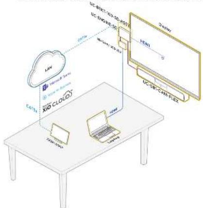
The Crestron® UC-B140-T Wall Mount UC Video Conference System for Microsoft Teams® software delivers a powerful professional solution for knowledge workers who want the Microsoft Teams software experience in small to midsize meeting spaces and conference rooms. It includes the UC-5B1-CAM-FLEX UC smart soundbar and camera for full-duplex wideband audio and HD video, a UC-BRK1-100-5D-ASSY for ease of installation, and a TSW-1060-B-S touch screen for system control.
a use the UC-B140-T system you must have the following:
• A Microsoft Teams or Skype® for Business software account
- An environment running Microsoft Exchange Server® software (2013 SP1 or later for on-promises installation or Microsoft 365® software for cloud) for scheduling and/or Skype for Business 2015 (on-promises installation or Microsoft 365 software for cloud).
flowchart
graph TD
    A["Cloud Service"] --> B["XRD CLOUD"]
    B --> C["LVM"]
    B --> D["LVM"]
    B --> E["LVM"]
    C --> F["Server 1"]
    D --> G["Server 2"]
    E --> H["Server 3"]
    F --> I["Device"]
    G --> J["Device"]
    H --> K["Device"]
» Check the Box
Item Qty
UC-B140-T1
CBL-CAT5E-7.7 ft (2.1 m) CAT5c Cable (P/N 6509924) 2
FWE-4803RU Pal Injector (P/N 6502429)
T5W-1060-B-5 10.1 in. Touch Screen, Black Smooth (P/N 6507651) 1
TSW-1060-TTK-B-S Tabletop Kit for TSW-1060, Black Smooth (P/N 6507729) 1
UC BRKT 100 SD ASSY Wall Bracket Assembly (Includes HD-CONV USB 200, UC-CONN-HD; and UC-ENGINE-SD, Power Cord, Connector Cover Screws with Tools, and Mounting Hardware) (P/N 6311093)
UC-SB1-CAM-FLEX UC Video Conference Smart Soundbar (P/N 6511046)
Additional Requirements
The following items (not included) are required to build the system.
• A video display, to be connected to the UC-ENGINE-SD

- USB keyboard and mouse to configure the system - USB to HDMI adapter to connect the UC-ENGINE-SD USB port to the display device via HDMI
- HDM ^® cable to connect a display device
• HDMI cable to connect on HDMI source
- Ethernet cable to connect the PoE injector to the network
• #1 Phillips hands screwdriver
- Drill with a 5/16 inch. bit (required for use with mounting anchors)
NOTE: Crestron recommends using Crestron cables only. For optimum performance, Crestron offers the UC-B-ACCY KIT which includes all of the required hookup cables and a wireless keyboard with integrated touchpad.
>> Install the Wall Bracket Assembly
The wall bracket assembly can be installed on a wall behind a display device, or attached to the rear of the display device. The wall bracket assembly includes mounting slots on both side edges, spaced 100, 200, and 900 mm vertically, so allow for attachment to other side of the display mounting plate. Axillary mounting holes are provided on each side for other mounting occasions. Carterina mounting holes are also provided for attachment to the building structure. Integrated, reusable cable tie wraps manage cable runs between the wall bracket and peripheral devices.
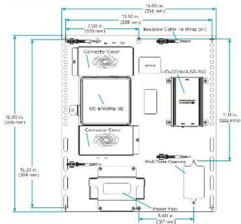
Dimensions and Callouts
text_image
5.00 in. (256 mm) 13.30 in. (338 mm) 7.00 in. (128 mm) Reversible Cable Tie Wrap (RC) Connector Cover UC-ENGLISH-SD Connector Cover HD-CO/S/USB-200 16.00 in. (405 mm) 16.30 in. (389 mm) T.11 in. (284 mm) Wall Gate Opening Power Padi 5.00 in. (27 mm)NOTES:
- The integrated cable tie wraps are reusnose. Take one to avoid damage to the cable tie wraps.
- The wall bracket assembly has an opening and pass through screw holes for placement over a US electrical wall box that can be covered by a decorative wall plate. If the wall plate opening will be positioned over an electrical wall box, larger screws will be secured to secure the decorative wall plate to the electrical box. Do not secure the wall bracket assembly with the wall plate opening screws.
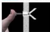
When mounting on a wall, the wall bracket assembly should be anchored to the wall. The screws and anchors included with the assembly one best suited for surfaces with 3/8 in. to 3/4 in. thickness. To use the included anchors, perform the following procedure.
-
Drill a 5/16 in pilot hole.
-
Fold the anchor in the middle end pinch
the and together

- Insert the anchor in the hole and tap flush with the wall.
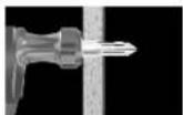
- Insert the included anchor key to pop the anchor open and lock it.
- Drive the screw partially into the anchor, leaving 1/4 in. of the screw exposed.
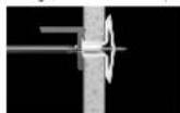
- Repeat steps 1 - 5 for the other anchor
- Place the wall bracket assembly on the screws and hand tighten the screws until the wall bracket is secured to the wall.
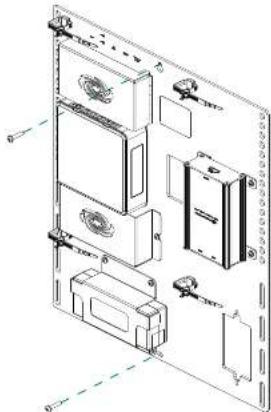
Install the Wall Bracket Assembly On a Wall
natural_image
Technical line drawing of a multi-panel electronic device with mounting holes and internal components (no text or labels)
Prepare for Hardware Hookup
On the wall bracket assembly, remove the connector covers located above and below the UC-ENGINE-5D to reveal the UC-ENGINE-5D's connectors.
NOTE: Each connector cover is secured to the wall bracket with a 6-32 Phillips screw. Use a #1 Phillips screwdriver to remove or install the screws. For additional security, replace the screws with the spanner screws includes with the UC-BRKT-100-5D-ASSY. A 1/4 in. driver bit is supplied to install the spanner screws.

Connect the System
UC-ENGINE-SD
Connect the CCS-UC4-KB-USB (sold separately), UC-SBI-CAM-FLEX, display, and LAN to the UC-ENGINE-SD. Connections are made to the top and bottom of the UC-ENGINE-SD.
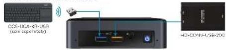
UC-ENGINE-SD, Bottom (as mounted)
text_image
CD-10CA-KD-10A (swire supernova) HD-CD-WY-USB-20CUC-ENGINE-SD
- Keyboard: Connect the USB dongie (supplied with CCS UCA KB USB) to a port on the UC-ENGINE-SD for local keyboard and mouse control.
- HD-CONV-USB-200: The HD-CONV USB 200 is already installed on the wall bracket assembly and connected to the UC-ENGINE-SD.
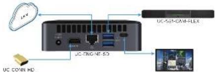
UC-ENGINE-SD, Top (as mounted)
flowchart
graph TD
    A["UC-GENE-SD"] --> B["UC-SEN-CAM-FLEX"]
    C["UC-GENE-SD"] --> D["UC-GENE-SD"]
    E["UC-GENE-SD"] --> F["UC-GENE-SD"]
    G["UC-GENE-SD"] --> H["UC-GENE-SD"]
    I["UC-GENE-SD"] --> J["UC-GENE-SD"]
    K["UC-GENE-SD"] --> L["UC-GENE-SD"]
UC CONN HD (Do not remove)
• LAN: Connect the CBL-CATSE-7 cable to the □□ portion on the UC-ENGINE-5D and to the corporate LAN.
NOTE: The UC-ENGINE-SD and PWE-4803RU (connected to the TSW-1060-B-S) must be on the same network switch.
- Display: Connect on HDMI cable (solid separately) to the USB-C port, on the UC-ENGINE-SD HDMI port (via a CSL-USBC-HD-9 sold as part of UC-B-ACCY KIT) and to the display.
- UC-SB1-CAM-FLEX: Connect the UC-SB1-CAM-FLEX to the ① port on the UC-ENGINE-5D and the PC port on the UC-SB1-CAM-FLEX with the USB cable that is included with the UC-SB1-CAM-FLEX.
- UC-CONN-HD: The UC-CONN-HD is already connected to the HDMI port on the UC-ENGINE-SD. Do not remove the UC-CONN-HD.
UC-SB1-CAM-FLEX
UC-SB1-CAM-FLEX Rear Panel
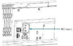
text_image
AC input- AC Power: Connect the AC power card to the UC SB1 CAM FLEX AC input and an AC receptacle.
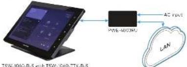
TSW-1060-B-S
flowchart
graph TD
    A["TSW-1060-D-5"] --> B["PWE-MOSIRU"]
    B --> C["AC input"]
    C --> D["LAN"]
• LAN PoE Connect the Ethernet cable included with the PWE-4803RU to the LAN PoE port on the T5W-1060-B-S and the LAN PoE port on the PWE-4803RU.
• LAN: Connect a CDL-CAT5E-7 cable to the LAN port on the PWE-4803RU and to the composite LAN.
NOTE: The PWE-4803RU and UC-ENGINE-SD must be on the same network switch.
• AC Power: Connect the AC power cord on the PWE-4803RU to an AC receptacle.
HD-CONV-USB-200
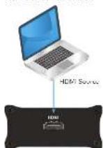
HD CONV USB 200
The HD-CONV-USB-200 is already installed on the wall bracket assembly and connected to the UC ENGINE SD. Connect an HDMI source to the HDMI port on the HD CONV USB 200 with an HDMI cable (sold separately).

Complete the Installation
- Bundle the cables with the integrated cable tie wraps. The cable tie wraps are reusable.
- Secure the connector covers with the spanner screws or the Phillips screws removed earlier from the wall product assembly.
- Connect the wall bracket assembly's power pack cord to a wall outlet.

Apply Power
When all connections are made, press the power button on the bottom of the UC-ENGINE-5D and apply power to all of the other devices in the system. The touch screen will start and will show its IP address.

Configure the System
Configure the Touch Screen
- Top Touch Here to Enable a Specific Application on the bottom of the screen. A list of applications is displayed.
- Top Teams Video, and then top Confirm. The touch screen will reboot.
- On a computer, open a web browser to the IP address of the TSW-106C-B-S. Log in and navigate to Settings > Applications
NOTES:
- The TSW-1063-B-S (via PWE-4803RU) and computer must be on the same network switch.
• A login with administrative rights for the TSW-1060-B-5 may be required. A. Enter the following an information in the appropriate fields:
- Teams Video PC Address: Enter the IP address or hostname of the UC-ENGINE-SD NOTE: The hostname is printed on a label offed to the UC-ENGINE-SD (mounted on the UC-BRKT-100-SD-ASSY).
- Teams Video PC Ports: By default, port number 49500 is used. If a different port number has been configured on the UC-ENGINE-SD, enter that port number instead.
- Teams Video Username: Enter the login username for the UC-ENGINE-SD. (The default username is "admin".)
-
Teams Video Password: Enter the login password for the UC-ENGINE-SD. (The default password is "afa".)
-
Click Save Changes.
For details, refer to the TSW-560/TSW-760/TSW-1060 Supplemental Guide (Dec. 7927) at www.crestran.com/manuals
Configure the UC-ENGINE-SD
Use the CCS-UCA-KB-USB keyboard (sold separately) and your Microsoft Teams or Skype account credentials to configure the UC-ENGINE-SD. Refer to the UC Video Conference Systems for Microsoft Teams Supplemental Guide (Doc. 0360) at www.crestron.com/manuals.

Additional Information
Scan or click the OR node for detailed product information.

HOMI
Compliance and Legal
Original instructions: The U.S. map an version of this document is the original instructions. All other languages are a translation of the original instructions.
The product warranty can be found at www.ewintra.com/warranty.
The product is possible that covers Crux, non products are listed at www.cruatic.com/legd/pulera.
Certain Electron products contain open source software. For specific information, please visit www.electron.com/bosera.com.
Crestron, the Creation logo, and Crestron ARC Cloud are either trademarks or registered trademarks of Crestron electronics, Inc. in the United States and/or other countries. HDMI and the HDMI logos are only trademarks or registered trademarks of HDMI Learning LLC in the United States and/or other countries. Microsoft's 365 Microsoft's Exchange Services, Microsoft's Tech, and the Computer their trademarks or registered trademarks of Microsoft Corporation in the United States or its affiliates. The website is also registered with the same website address at www.xc.com in this document. The website is also registered with the same website address at www.xc.com in the United States or its affiliates. Crestron is not responsible for errors in typography or photography.
©2019 Creation Electronics, Inc.
Crentron Electronics, Inc. 15 Valve Drive, Rockhigh, NJ 07047 Tel: 958/CRISERON Fax: 2017/65/75/8 www.c102.com.cn
Quick Start - Doc. 0462D (2053758) 06/17/19 Specifications subject to change without notice