
DR-3000 - Varmeapparat Toyotomi - Gratis brugsanvisning og manual
Find enhedens vejledning gratis DR-3000 Toyotomi i PDF-format.


Brugerspørgsmål om DR-3000 Toyotomi
0 spørgsmål om dette apparat. Besvar dem du kender, eller stil dit eget.
Stil et nyt spørgsmål om dette apparat
Download vejledningen til din Varmeapparat i PDF-format gratis! Find din vejledning DR-3000 - Toyotomi og tag din elektroniske enhed tilbage i hånden. På denne side er alle dokumenter nødvendige for brugen af din enhed offentliggjort. DR-3000 af mærket Toyotomi.
BRUGSANVISNING DR-3000 Toyotomi
TOYOTOMI
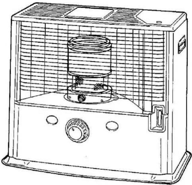
PORTABLE KEROSENE HEATER
OPERATION AND MAINTENANCE INSTRUCTIONS
Model DR-3000
natural_image
Line drawing of a portable air conditioner unit with cooling fan and control panel (no text or symbols)ASSEMBLY AND OPERATION INSPECTION AND ASSEMBLY
NOTE: Please save the shipping carton and packing materials for future storage of your heater.
1. REMOVE PACKING MATERIALS
Open the grille by raising the lower right hand corner of grille and pulling straight out. Remove the styrofoam packing wedge from under the top plate of the cabinet to release the heat chamber assembly. Lift the heat chamber, in its protective packing, out of the cabinet.
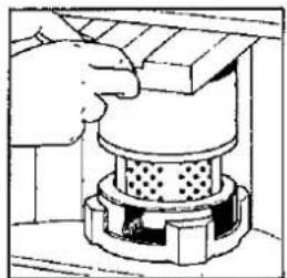
2. REPLACE THE HEAT CHAMBER
Remove the styroform packing, and replace the heat chamber assembly. Point the wire handle to the front of the heater.
Close the grille.
natural_image
Illustration of a hand pressing down on a mechanical component (no text or symbols visible)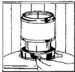
natural_image
Simple line drawing of a cylindrical device with a base and top, mounted on a surface (no text or symbols)3. INSTALL THE BATTERIES
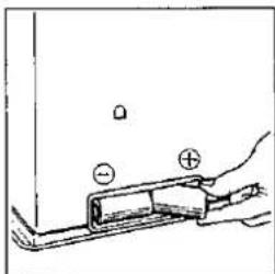
Locate the battery holder on tha back of your heater.
- Insert the 2 "D" size batteries according to the plus (+) and minus (−) markings.
natural_image
Simple line drawing of a hand holding a small electronic component with polarity markers (no text or symbols)4. CHECK THE HEAT CHAMBER
If the heat chamber is raised, put it down and inlay it.
NOTE: If the heat chamber is raised, it can cause smoke and soot.
FUELING
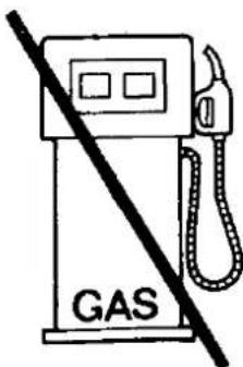
WARNING: Use only clean kerosene.
Never use gasoline or other flammable liquids.
-
Open the fuel tank lid on the top of heater cabinet and lift out the removable fuel tank. Turn the removable tank upside down and remove the fuel tank cap.
-
Insert the straight tube of the manual siphon into the kerosene container. Insert the siphon's flexible hose into the removable fuel tank opening.
-
Turn the air vent knob on the top of the siphon clockwise to close the vent. Start the flow of kerosene by squeezing the bulb of the siphon vigorously six or seven times. Once flow begins, it is no longer necessary to squeeze the bulb.
-
Watch the fuel gauge on the removable tank to avoid overfilling. When it shows half, stop flow by turning the air vent knob counterclockwise.
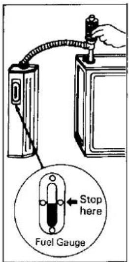
NOTE: Be careful to avoid overfilling the tank, especially with very cold kerosene. Overflow might occur due to expansion when the fuel warms up.
-
Remove the siphon carefully, allowing excess kerosene to drain from the tube back into the container. Replace fuel tank cap and tighten it securely. Be sure to wipe away any spilled kerosene from tank and other heater parts.
-
After making sure fuel tank cap is tightly fastened, invert tank and replace into heater body.
CHECK BEFORE LIGHTING
- LEVEL THE HEATER
The heater should be operated on a firm, level floor.
NOTE: If your heater is not level, change locations.
Do not prop it with books or other objects.
- ENGAGE THE AUTOMATIC EXTINGUISHER
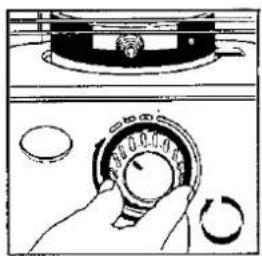
The automatic extinguisher is engaged automatically by turning the wick adjuster knob clockwise.
natural_image
Illustration of a hand holding a circular dial with three other circular components, no text or symbols present.LIGHTING
NOTE: When you first use your new heater, ignite it out of the living area of your house, either in a garage or an area outside protected from strong drafts. Burn it for about 15 minutes to remove all of the protective oil present on the burner parts. If this 15 minutes "burn-in" is done inside, some objectionable odor will be observed. This procedure is necessary ONLY THE FIRST TIME you ignite your heater.
NOTE: If you have fueled your heater for the first time, or if you are refueling it after it has been out of fuel for a long time, you will need to wait about thirty (30) minutes for the wick to become fully saturated.
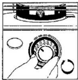
- Turn the wick adjuster knob clockwise until it stops.
As the wick rises within the heater, the wick adjuster knob turns with some resistance and makes a sound like the winding of a clock. Once the wick has reached its proper height, the automatic extinguisher is fully engaged.
The wick adjuster knob can now move freely left or right to adjust the flame.
- AUTOMATIC LIGHTING
Gently push the igniter button, the igniter coil should glow and touch the wick.
When flame appears, release the igniter button.
NOTE: If you have difficulty igniting wick, push back the igniter button very slightly to remove the igniter coil from direct contact with the wick.
- LIGHTING WITH A MATCH
You should not have to light the heater with a match, but should it become necessary, open the grille, lift the heat chamber up by holding the wire handle and touch the match to the top of the wick. Do not allow burned parts of the match to fall or remain on the wick.
NOTE: To restore the automatic igniter system to proper operation, replace worn out batteries, or if the igniter coil defective, replace it.
- Be sure that heat chamber is properly seated by moving the wire handle left and right. If the movement is cough and jerky, it indicates that the heat chamber has not seated properly.
NOTE: An improperly seated heat chamber can cause high flame, smoke, and potential damage to the heater itself. Do not leave the heater until you have determined that the flame is burning normally, which will be described in the following section.
natural_image
Diagram showing a hand holding a rotary dial with three circular components, no text or symbols present.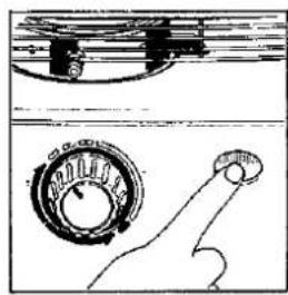
natural_image
Technical line drawing of a mechanical component with no visible text or symbols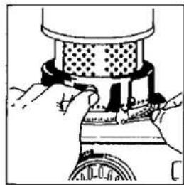
natural_image
Illustration of hands operating a mechanical device with a perforated top component (no text or symbols visible)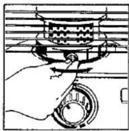
natural_image
Hand holding a mechanical component with a ring and lever (no text or symbols visible)ADJUSTING THE FLAME
- After lighting, wait for the heat chamber to reach operating temperature. This will take ten-fifteen minutes, after which the flame will be visible through the glass cylinder.
- CHECK THE FLAME LENGTH
Look at the flame and check its length. Flame length is not necessarily even or uniform around the circumference of the center disk. Some areas may be lower than others, but on maximum wick-height, flame length should average between 1 cm (3/8 in.) to 2.5 cm (1 in.).
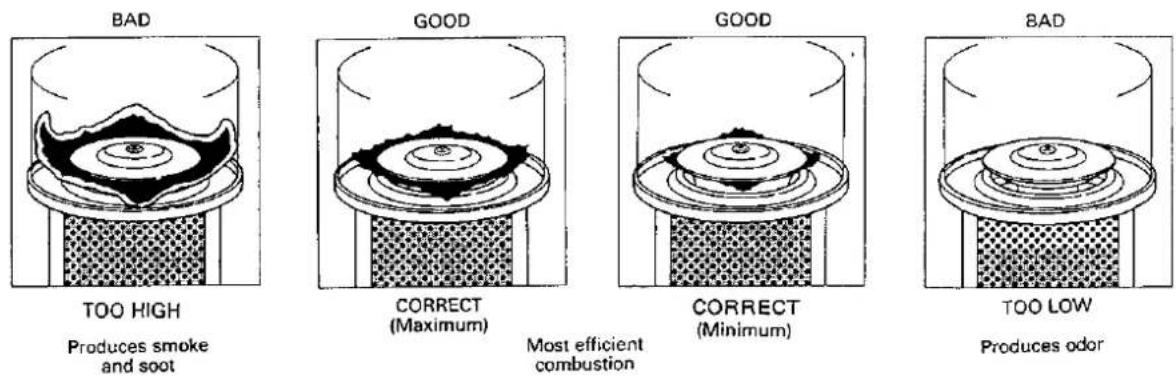
If necessary, raise or lower the wick by turning the wick adjuster knob to produce the proper flame condition.
NOTE: Do not operate your heater wick set TOO LOW or TOO HIGH. Doing so will decrease combustion efficiency and increase production of unwanted emissions. When operating heater, be sure wick is high enough to keep the primary heat chamber heated to a uniform red glow from its top to bottom.
- ADJUSTMENT OF MAXIMUM WICK HEIGHT
After using the heater over a long period of time, you may observe that the flame length in the heat chamber does not reach its normal level in several minutes after lighting. When this condition is observed, it means that the wick height needs adjusting using the unique wick life extender.
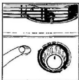
To adjust the wick height using the wick life extender mechanism, first release the automatic extinguisher by pushing the manual shutoff button.
natural_image
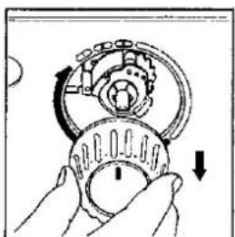
Illustration of a hand holding a small compass with a musical note above (no text or symbols)Pull the wick adjuster knob out completely. (It can be removed completely from its shaft.)
natural_image
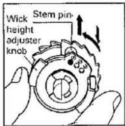
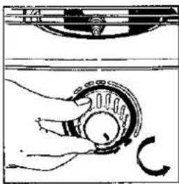
Illustration of a hand holding a mechanical component with directional arrows indicating motion (no text or symbols)The wick height adjuster knob, with three small holes marked ①, ②, and ③, can be seen. The stem pin is engaged in one of the holes. Pull the control dial toward you and change the location of the pin from ① to ②, or from ② to ③. Each step from pin ① to ② will raise the maximum wick height by 2 mm per step. After this adjustment, replace the wick adjuster knob.
When suitable flame length can no longer be achieved even on pin position ③, it is time to clean and replace the wick. AFTER REPLACING THE WICK, CHECK THE OPERATION OF THE AUTOMATIC EXTINGUISHER BEFORE LIGHTING YOUR HEATER.
NOTE: Never use positions ② or ③ until position ① no longer gives adequate flame length.
EXTINGUISHING THE FLAME
- Turn the wick adjuster knob counterclockwise until it stops. This requires about a half turn. At this point, the flame is completely extinguished and the heater is off.
NOTE: DO NOT use the automatic extinguisher to routinely turn off the heater. Automatic extinguishing should occur only when the heater is jarred or tipped. Using the automatic extinguisher to turn off the heater will cause odor, smoke and soot.
-
Make sure tha flame is out completely.
-
Do not try to relight the heater for at least three (3) minutes after extinguishing it off as this may cause smoke and odor.
MANUAL SHUTOFF
When quick shutoff is necessary, push the manual shutoff button.
NOTE: For routine turn-off, DO NOT use the Manual Shutoff or activate the Automatic Extinguisher by jarring the heater. These methods may cause unwanted odor, soot and smoke. Only the wick adjuster knob should be used for normal shutoff.
natural_image
Mechanical diagram showing a hand operating a rotating mechanical component with a curved arrow indicating rotation (no text or symbols present)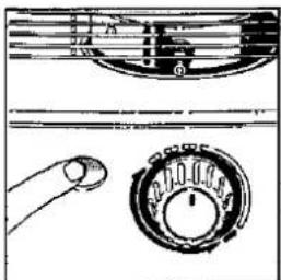
natural_image
Pure electrical circuit lines without any symbolsREPLACEMENT OF PARTS
REPLACING THE WICK
WARNING: Before disassembling your heater, allow it to cool completely.
-
To release the automatic extinguisher, push the manual shutoff button.
-
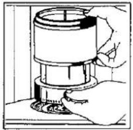
After the heat chamber has cooled completely, open the grille and remove the heat chamber.
-
Grasp the wick adjuster knob and pull it straight off the wick adjuster shaft.
-
Lift out the removable fuel tank and set it aside. Remove the three (3) screws at the side and rear of the cabinet by using the screwdriver, and lift the cabinet off, bringing it slightly forward.
-
Disconnect the two electrical leads (red and white) attached to the battery holder.
-
Remove the four (4) wing nuts around the wick adjuster assembly. Lift the assembly off the heater while moving it slightly back and forth.

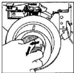
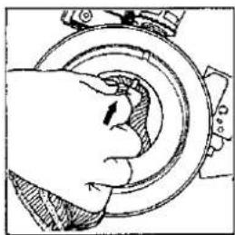
- Slide two fingers between the orange band on the wick and the silver wick sleeve attached to the wick adjuster. Lift the pins in the wick off the slots in the wick sleeve.
After lifting all three (3) pins off the slots, fold the wick and remove it.
Leave the wick sleeve in place.
- Replace the wick adjuster knob on the wick adjuster shaft.
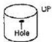
Place the wick adjuster assembly on its side. Insure that the wick is in the wick adjuster with the holes in the section of the sleeve closer to the inside burn chamber.
At this time, you must line up the three (3) openings in the wick adjuster 1) the holes in the sleeve, 2) the diagonal slots in the fixed part of the wick adjuster, and 3) the slots in the moving part of the wick adjuster controlled by the wick adjuster knob.
WARNING: NEVER replace the sleeve upside down.
-
Fold the new wick in quarters and insert it into the assembly. Place one of the pins in one of the lined-up openings. If you experience difficulty, gently turn the wick adjuster knob clockwise. Then place the two other pins, turning the wick adjuster knob if necessary. Do not bend the sleeve.
-
Finally, gently press the wick, all along its circumference, against the adjuster to insure that it is firmly in place.
-
Lower the wick adjuster assembly into the fuel tank, guiding the tail of the wick so it fits over the primary air tube and evenly into place.
Point the wick adjuster shaft to the front of the heater. Insure that the wick adjuster is centered over the studs on the fuel tank.
NOTE: The space between the wick adjuster and the primary air tube should be even all around.
NOTE: Make certain the top of the wick adjuster and the top of primary air tube are the same height. If they are uneven, the flames tend to be uneven, too.
natural_image
Hand operating a mechanical component with a circular dial and tool, no visible text or symbols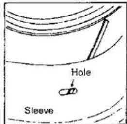
natural_image
Line drawing of a hand pressing down on a circular mechanical component (no text or symbols)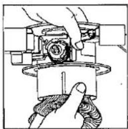
natural_image
Illustration of hands operating a mechanical device with a gear and base (no text or symbols visible)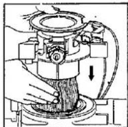
natural_image
Mechanical assembly diagram showing a hand operating a valve with a downward arrow indicating motion (no text or symbols present)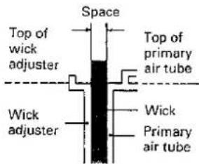
-
Tighten the 1 four (4) wing nuts around the wick adjuster assembly.
-
Operate the wick adjuster knob to be sure the wick moves smoothly up and down.
AFTER REPLACING THE WICK, CHECK THE OPERATION OF THE AUTOMATIC EXTINGUISHER.
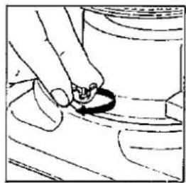
Wich height on position① of wick life extender should be 8 mm (5/16 in.), when wick adjuster knob fully clockwise. Be sure to check.
NOTE: Remember always start new wick on position ① of wick life extender.
NOTE: If wick does not move smoothly and easily, or wick height is more or less than 8mm, do not use heater, disassemble and repeat items 8 through 13.
NOTE: If any ragged edges appear on the top of the wick, trim them with a scissors carefully. DO NOT cut the body of the wick.
Remove the wick adjuster knob from the wick adjuster shaft once more.
-
Reconnect the red and white electrical leads to the battery holder.
-
Replace the cabinet and secure it into position with three (3) screws.
Replace the wick adjuster knob on the wick adjuster shaft. Install the heat chamber. Grasp the wire handle, then turn the heat chamber left and right to insure that it is properly seated. Once again check the proper operation of the automatic extinguisher.
NOTE: Before lighting a new wick for the first time, turn the wick to its lowest position.
Allow the wick to saturate with kerosene for about thirty (30) minutes.
natural_image
Hand holding a small object over a surface, no visible text or symbols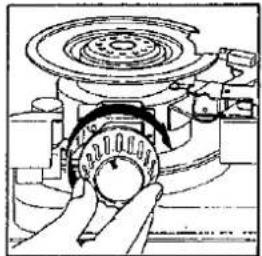
natural_image
Technical line drawing of a mechanical device with a hand operating a rotating knob (no text or symbols present)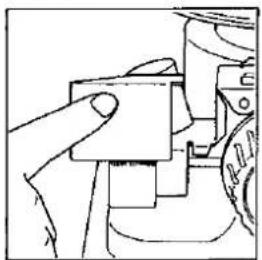
natural_image
Hand pressing a component on a mechanical part (no visible text or symbols)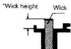
8 mm (5/16 in.)
natural_image
Hand inserting a cable into a socket (no text or symbols visible)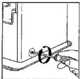
natural_image
Simple line drawing of a hand holding a tool with a circular component, no text or symbols presentREPLACING THE IGNITER COIL
WARNING: Before replacing the igniter coil, allow the heater to cool completely.
1. FIRST CHECK THE BATTERIES
When the igniter coil no longer glows sufficiently to light the wick, replace the batteries. If proper glow is not restored, the igniter coil may be defective.
2. CHANGE THE IGNITER COIL
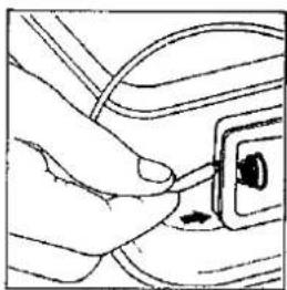
Remove the batteries from the battery holder.
Release the automatic extinguisher, and remove the heat chamber as described in Items 1 and 2 of the preceding section.
Note that the igniter coil fits into a bayonet socket the same way a flashlight bulb fits into its holder.
To remove the igniter coil, push it in and twist it in either direction while holding the sides of the socket with your other hand.
Install the new igniter coil by pressing it into the socket and turning.
Replace the heat chamber, and reinstall the batteries.
natural_image
Illustration of a hand using a mechanical presser to press a cylindrical component (no text or symbols visible)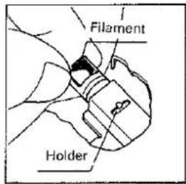
STORAGE
At the end of each heating season, or when you do not plan to use your heater for an extended period of time, the following procedures are recommended:
1. DRAIN FUEL SUB TANK
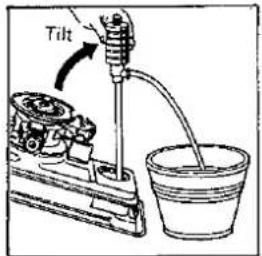
After you have burned your heater dry, a small amount of kerosene will remain in the fuel sub tank. It should be removed in order to avoid contamination when the heater is refueled at a later date. To do this, disassemble the heater as described in items, 1 through 4 under "REPLACING THE WCIK". Remove the fuel acceptance fitting from the hole in the fuel sub tank.
Tilt the drip tray toward the hole, and remove the remaining kerosene with a siphon or a small syringe.
Replace the fuel acceptance fitting.
Replace the cabinet and the heat chamber.
2. REMOVE BATTERIES FROM BATTERY HOLDER
3. STORE HEATER
The original shipping carton is the best place to store your heater. If you do not have original packing materials, cover the heater with a large plastic bag and store in a dry place.
SPECIFICATIONS
| Model DR-3000 | |
| Heat rating | 2,600 kcal/h |
| Fuel tank capacity | 4.7 ℓ |
| Burning time/tank* | 16.8 Hours |
| Size (W x D x H) | 586 x 304 x 439 |
| Weight | 12.0 kg |
| Wick adjuster | Wick life extender mechanism |
| Igniter | Automatic, powered by two (2) “D” size batteries |
* Depending on wick setting, condition and fuel quality.
COMPONENT PARTS
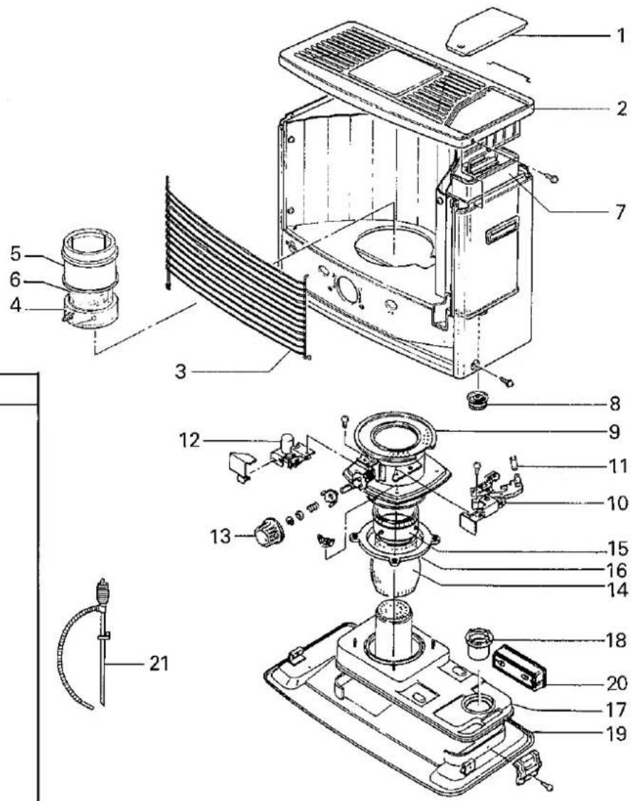
| REF # | PART NAME |
| 1. | Tank lid |
| 2. | Top plate |
| 3. | Grille |
| 4. | Heat chamber assembly |
| 5. | Upper glass cylinder |
| 6. | Lower glass cylinder |
| 7. | Removable fuel tank |
| 8. | Fuel filler cap |
| 9. | Wick adjuster assembly |
| 10. | Igniter unit |
| 11. | Igniter coil |
| 12. | Pendulum assembly |
| 13. | Wick adjuster knob |
| 14. | Glass fiber wick |
| 15. | Wick holder |
| 16. | Rubber packing |
| 17. | Fuel sub tank |
| 18. | Fuel acceptance fitting |
| 19. | Drip tray |
| 20. | Battery holder |
| 21. | Manual fuel siphon |
TOYOTOMI
TOYOTOMI CO., LTD.
5-17, Momozono-cho
Mizuho-ku, Nagoya, Japan
- TOYOTOMI
- PORTABLE KEROSENE HEATER
- OPERATION AND MAINTENANCE INSTRUCTIONS
- ASSEMBLY AND OPERATION INSPECTION AND ASSEMBLY
- REMOVE PACKING MATERIALS
- REPLACE THE HEAT CHAMBER
- INSTALL THE BATTERIES
- CHECK THE HEAT CHAMBER
- FUELING
- CHECK BEFORE LIGHTING
- LIGHTING
- ADJUSTING THE FLAME
- EXTINGUISHING THE FLAME
- MANUAL SHUTOFF
- REPLACEMENT OF PARTS
- REPLACING THE WICK
- REPLACING THE IGNITER COIL
- FIRST CHECK THE BATTERIES
- CHANGE THE IGNITER COIL
- STORAGE
- DRAIN FUEL SUB TANK
- REMOVE BATTERIES FROM BATTERY HOLDER
- STORE HEATER
- SPECIFICATIONS
- COMPONENT PARTS
Mærke : Toyotomi
Model : DR-3000
Kategori : Varmeapparat