
M5500 - Ukategoriseret KUBOTA - Gratis brugsanvisning og manual
Find enhedens vejledning gratis M5500 KUBOTA i PDF-format.

Brugerspørgsmål om M5500 KUBOTA
0 spørgsmål om dette apparat. Besvar dem du kender, eller stil dit eget.
Stil et nyt spørgsmål om dette apparat
Download vejledningen til din Ukategoriseret i PDF-format gratis! Find din vejledning M5500 - KUBOTA og tag din elektroniske enhed tilbage i hånden. På denne side er alle dokumenter nødvendige for brugen af din enhed offentliggjort. M5500 af mærket KUBOTA.
BRUGSANVISNING M5500 KUBOTA
CONTENTS
OPERATOR'S MANUAL FOR M4500/ M4500DT/M5500/ M5500DT/ M7500/ M7500DT
CONTENTS
SERVICING OF TRACTOR
SAFETY PRECAUTIONS
INSTRUMENTS AND CONTROLS
OPERATION
FUEL AND LUBRICANT SPECIFICATIONS
MAINTENANCE
STORAGE
SPECIFICATIONS
WIRING DIAGRAM
FORWARD
Your are now the Proud owner of a Kubota Tractor. This tractor, a product of Kubota quality engineering, is made from the finest materials under a rigid quality control system and will give you long, reliable service. Careful reading of this manual will insure that you get maximum performance from the tractor. This manual will familiarize you with the controls and operation of the tractors and contains many helpful maintenance and safety instructions. It is Kubota's policy to make immediate use of every advance in our research. This immediate application of new technology may cause some limited portions of this manual to be outdated. Kubota dealers and distributors will have the most up-to-date information regarding any changes made on the tractor that are not included in this manual. Please do not hesitate to consult with them.

IMPORTANT NOTICE
This is the industry's "Safety Alert Symbol". This symbol is used to call your attention to items or operations that could be dangerous to you or other persons using this equipment. Please read these messages carefully. It is essential that you read the instructions and safety regulations before you attempt to assemble or use this unit.
CONTENTS
Servicing of Tractor 1
Safety Precautions 2
Safety Section 3
- Tractor operations 3
- Handling fuel and other combustable materials....3
- Precautions for parts of tractor 4
- Common machinery hazards 5
- Check points 5
Instruments and Controls 6
- Instrument panel
- Controls
Operation 12
- Introduction 13
- World wide graphic symbols 13
- Break-in procedures 13
- Prestarting inspection 14
- Starting and stopping the engine 14
- Operation the tractor 14
- Performance checks during operation ..... 15
- Operating the tractor on the farm 15
- Wheel adjustment 19
- Fender adjustment 21
- Weighting the tractor 21
Fuel and Lubricant Specifications 22
- Fuels 23
- Lubricants....23
Maintenance 26
- Break-in procedure 27
- Lubrication intervals during break-in period ..... 27
- Other checks during break-in period 27
- Service and lubrication intervals 27
- Periodic service procedures ..... 27
- Fuel system maintenance 30
- Transmission/hydraulic system maintenance 32
- Cooling system 33
- Electrical system 34
- Fan belt adjustment 37
- Periodic service schedule 38
- Battery trouble shooting 39
- Engine trouble shooting 40
Storage 41
- Tractor storage 41
- Removing the tractor from storage 41
Specifications 42
- Specifications....43
- Tractor speed 45
Wiring diagram 46
SERVICING OF TRACTOR
Your KUBOTA Dealer is interested in you and your new tractor. Your dealer is a skilled and knowledgeable professional. He has the know-how to assure that you will receive the most value from your tractor and implements.
Read this manual carefully. The manual describes the correct operating procedures for all the various tractor components and outlines all required service procedures. Upon reading the manual, you will discover that you can do most of the required servicing yourself. If you need assistance with servicing, or if you need parts see your KUBOTA Dealer. He is there to serve you.
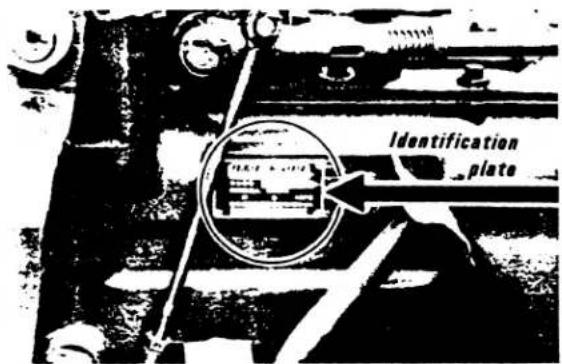
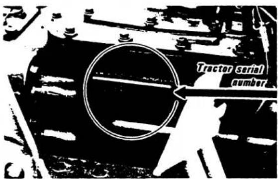
When ordering parts, be prepared to give the dealer both the engine and tractor serial numbers.
The tractor serial number is located on the right side of the transmission case. The engine serial number is stamped on an unpainted plate on top of the fuel injection pump. The fuel injection pump is located on the right hand side of the engine.
Locate the serial numbers now and record them in the spaces provided below.

Before using implements not sold by KUBOTA DISTRIBUTOR, contact your nearest dealer, regarding safety in its application.
KUBOTA TRACTOR
Tractor Serial No. ____
Engine Serial No. ____
Date of Purchase ____
(To be filled in by purchaser)
![[M4500(DT)] Engine serial number](/content/2026/05/867607/images/a72a36a99692bd1faacb23a51c35c1df609c70b9e66d3b16ac30cc3bf0f1391a.jpg)
![[M5500(DT)] [M7500(DT)] Engine-serial number](/content/2026/05/867607/images/a1ac0225bb037e0f0943a0f9e5fb5356ddd3624a08e32c121ef7654840b1a8b6.jpg)

SAFETY PRECAUTIONS
- TRACTOR OPERATIONS .....
- HANDLING FUEL AND OTHER COMBUSTABLE MATERIALS.....
- PRECAUTIONS FOR PARTS OF TRACTOR ....
■ Radiator ....
■ Battery ....
■ Hydraulics ....
■ Power take-off ....
■ Differential lock ....
■ Drawbar ....
■ Implement safety .....
-
COMMON MACHINERY,
-
CHECK POINTS
SAFETY SECTION
While equipment safety is a uniquely human preoccupation, people operating equipment continue to be the greatest hazard to themselves. In many cases, it is the failure of human judgement that results in the most severe accidents. Carelessness, taking unsafe short cuts, ignoring warnings and operating machinery with which people are unfamiliar are most often the cause of serious accidents where people are hurt or killed.
This safety section has been prepared to provide you with information that will help you avoid unsafe operating conditions. This section of the manual is a review of general safety precautions that relate to the tractor and farm machinery in general. Before operating your tractor, read this section and the entire manual carefully. Commit the following safety precautions to memory, make them part of your everyday work habits. Be sure you understand all the operating procedures for the tractor and that you are familiar with the tractor instruments and operating mechanisms before you operate the tractor.
Once you have familiarized yourself with the tractor and its operating characteristics, be aware that this familiarity can cause carelessness. Familiarity with your tractor does not mean that safety can be forgotten. A renewed commitment to safety must be made every day. Remember, SAFETY IS NO ACCIDENT!
1. TRACTOR OPERATIONS
This section contains general tractor operating safety suggestions as well as specific suggestions for safe maintenance and operation of various tractor components.
(1) Do not start the tractor unless you are seated in the driver's seat.
(2) Do not allow anyone, other than the driver, to ride on the tractor, drawbar or three point hitch at any time.
(3) When operating the tractor on public roads, obey all traffic laws and local regulations pertaining to the operation of farm equipment.
(4) Lock the brake pedals together whenever operating the tractor on the road. Uneven braking at road speed may cause the tractor to swerve uncontrollably.
(5) Exercise extreme caution when operating the tractor up and down or across hillsides. Before starting hillside operation, widen the wheels to the widest position. Keep the brake pedals locked together and the tractor in gear. Avoid sharp turns or sudden movement with the tractor. Always carry any attached implements low. Never allow the tractor to freewheel downhill.
(6) Keep a safe distance between the tractor and the edge of cliffs, gullies and ditches. The shoulders of such drop-offs may be soft and give way under the weight of the tractor wheel allowing the tractor to tip or fall.
(7) Do not tow the tractor at a speed greater than it would travel under its own power.
(8) Never tow a trailer that weighs more than twice the weight of the tractor unless the trailer is equipped with brakes.
(9) Exercise extreme caution when pulling heavy loads at road speed. Avoid sudden application of the brakes. When travelling downhill, keep the tractor in low gear in order to maintain control without overworking the brakes.
(10) Always wear appropriate personal protective equipment such as eye protection, ear plugs, head protection, gloves, steel-toed shoes, air filtration equipment or other kinds of body protection that may be appropriate for the kind of work you are doing. Be aware that loose fitting clothing can get caught in moving parts which may result in personal injury.
(11) When working with crop chemicals, protect your eyes, skin and respiratory system from damaging contact with the chemicals.
(12) Do not operate your tractor with worn-out, obsolete equipment or equipment that is incompatible with the tractor.
(13) Do not perform maintenance or repairs to the tractor or other machinery if you are not qualified to do so. A machine that is not repaired properly may be unsafe to operate. If, at any time, you have any question about the repair and maintenance procedures for your KUBOTA Tractor, see your KUBOTA Dealer.
(14) Do not perform any maintenance work to the tractor or attached implements while they are in motion unless such repair is specifically recommended by the manufacturer.
(15) While operating the tractor always be aware of any noticeable changes in the operating characteristics of the tractor, including changes in the color of the engine exhaust and unusual sounds or vibrations. Unusual operating characteristics often warn of a more serious underlying problem that may not only endanger the operator's safety, but may indicate a serious mechanical malfunction.
(16) NEVER OPERATE THE TRACTOR OR ANY AGRICULTURAL EQUIPMENT WHILE UNDER THE INFLUENCE OF ALCOHOL OR OTHER DRUGS.
(17) Keep a fire extinguisher near your fuel filling and fuel storage areas. Be sure the extinguisher is properly maintained and that you are familiar with its use.
(18) Keep a first aid kit in a convenient location.
2. HANDLING FUEL AND OTHER COMBUSTABLE MATERIALS
(1) Store fuel in a well-ventilated area.
(2) Never refuel the tractor while the engine is running or while the engine is hot.
(3) Do not smoke, light matches or expose open flame while using starting fluid, filling the fuel tank, or servicing the fuel system.
(4) Wipe up any spilled fuel after you have filled the tractor fuel tank.
3. PRECAUTIONS FOR PARTS OF TRACTOR
■ Radiator
(1) Do not open the radiator cap while the engine is hot. The tractor has a pressurized cooling system. Boiling water may gush out when the cap is removed.
(2) Add coolant to the radiator only when the engine is stopped or while it is idling. To avoid being scalded when the pressure cap is removed, turn the cap slightly to release pressure before opening the cap all the way.
(3) Do not pour cold water into an overheated engine. The cylinder block may crack.
(4) Keep the radiator screen clean and free of debris.
■ Battery
(1) Disconnect the ground cable from the battery before making adjustments or repairs to the tractor electrical system.
(2) Avoid making sparks or exposing open flame around the battery. If battery charging is required, turn off the battery charger before connecting and disconnecting the charger from the tractor battery.
(3) Before using a jumper or booster battery read the instruction in the electrical service section of this manual.
(4) Handle electrolyte with care. Keep electrolyte away from bare skin and eyes and clothing.
(5) When disconnecting the battery cable, disconnect the negative (−) cable first. When connecting the battery cables, connect the positive (+) cable first.
■ Hydraulics
(1) The hydraulic system operates by pumping oil at extreme pressure. If a leak develops in a hydraulic line it may be almost invisible. If you suspect that there is a hydraulic leak in a line or fitting, do not place your hand or arm near the suspected leak. Use a piece of cardboard or wood held near the suspected leak to show the exact location of the leak. Hydraulic fluid is pumped at sufficient pressure to penetrate the skin and enter the blood stream causing serious personal injury. If you suspect you have been injured by escaping hydraulic fluid, see a doctor at once.
(2) Before disconnecting any hydraulic lines, turn the engine off and where possible relieve hydraulic pressure.
(3) If repairs have been made to the tractor hydraulic system, check all fittings, lines, and hoses for damage before starting the tractor. Once the tractor is started, make a careful and complete visual inspection of all hoses and fittings looking for leaks that may have developed as the system was operated under pressure. If any leaks are discovered, make necessary repairs immediately.
■ Power take-off
(1) Before disconnecting an implement PTO shaft from the tractor PTO shaft be sure the engine is off, the PTO clutch is disengaged or the PTO gearbox is in neutral and that the PTO shaft has stopped turning.
(2) Keep all PTO shields in place whenever the PTO shaft is being used. When the PTO shaft is not being operated, replace the tractor PTO shaft cover. This cover will prevent injury and help keep the shaft clean.
■ Differential lock
(1) Read the differential lock operating instructions before using the differential lock.
(2) Do not attempt to turn the tractor with the differential lock engaged.
(3) Do not operate the differential lock while operating the tractor on the road.
Drawbar
(1) All pulling or towing, other than that done with three point hitch mounted implements, should be done from the drawbar. DO NOT ATTACH ANY IMPLEMENT, PULL-CHAIN OR ROPE TO ANY POINT ON THE TRACTOR ABOVE THE CENTER LINE OF THE REAR AXLE.
(2) When attaching drawn equipment to the drawbar, back the tractor up so the implement attaching hole is past the drawbar mounting hole. The holes may then be lined up as the tractor moves forward away from the implement.
(3) Whenever possible, heavy loads should be hitched directly to the drawbar. If it becomes necessary to use a chain to pull a heavy load, take up slack in the chain slowly.
■ Implement safety
When installing or using the implement, be sure to read the instruction for the implement and keep the precautions in mind.
(1) Use front counterweights of appropriate weight whenever operating the tractor with a three point hitch mounted implement.
(2) Whenever attaching a three point PTO driven implement to the tractor, turn off the engine and set the parking brake before attaching the PTO shaft to the tractor.
(3) Use the three point hitch lock to hold the three point hitch in the raised position when transporting a mounted implement over the road.
(4) When mounting or dismounting an implement to or from the three point hitch, do not stand between the implement and the tractor.
(5) If the tractor is operated with a front loader, be sure there is sufficient counter weight on the rear wheels to offset the weight of the loader. An under weighted rear axle will result in loss of traction when the loader bucket is loaded.

4. COMMON MACHINERY HAZARDS
■ Whenever you are operating any type of farm equipment including your KUBOTA Tractor, you should be aware of certain kinds of common machinery hazards. These include:
(1) PINCH POINTS. Machinery components that can come together and compress or pinch.
(2) WRAP POINTS. As on the end of an exposed shaft or the middle of an exposed PTO shaft. Wrap points are particularly dangerous when operating equipment while wearing loose fitting clothing.
(3) SHEAR POINTS. When operating machinery equipped with blades, hydraulic cylinders and other moving parts, be aware of shear points, places where two machinery components come together in such a way that they can cut or shear.
(4) CRUSH POINTS. Crush points are sometimes the most difficult to detect. Crush points include tires and wheels but may also include, for example, the area between two movable pieces of machinery, or the space under a piece of machinery that has been jacked up or is resting on blocks and that may not be secure. Other common hazards include freewheeling parts such as inertia wheels or fly wheels, thrown objects, store energy (such as in compressed springs) and second party accidents involving other people.
5. CHECK POINTS
■ Always check the following before operating the tractor:
(1) TIRE PRESSURE. If the tires are low, inflate them to the correct pressure.
(2) PROTECTIVE SHIELDS. Be sure all protective shields are in place and secured.
(3) STEPS AND PLATFORMS. Check the tractor mounting steps and step plates. Be sure they are secure and free of mud, oil or other slippery material.
(4) ROPS AND SEAT BELTS. If the tractor is equipped with a ROPS and seat belts, be sure the ROPS mounting bolts are tight. Check the seat belt for signs of wear that could effect its integrity under stress. Be sure the seat belt is securely fastened to the tractor.
(5) SEAT POSITION. The seat should be positioned so that the control levers and switches can be reached easily and comfortably.
(6) INSTRUMENTS. Once the tractor has been started, check all instruments to assure they are operating correctly. Do not operate the tractor unless all instruments and warning lights are functioning.
(7) FLUID LEAKS. Once the tractor has been started, allow it to warm up for several minutes before operating under a load. While the tractor is warming up, make a visual inspection of the machine looking for evidence of water or oil leaks.
Keeping the tractor clean and free of excess debris will make for safer operation by eliminating material that may be slippery and can hide evidence of mechanical problems. It is important that the tractor be maintained in accordance with this manual. Failure to maintain the tractor properly may create an unsafe operating situation.
MAKE ALL ADJUSTMENTS AND DO ALL SERVICE PROCEDURES AT LEAST AS OFTEN AS IS SPECIFIED IN THIS MANUAL. REMEMBER THAT THE PROCEDURES RECOMMENDED IN THIS MANUAL ARE FOR AVERAGE OPERATING CONDITIONS. YOUR OPERATING CONDITIONS MAY REQUIRE MORE FREQUENT ATTENTION TO SPECIFIC ADJUSTMENTS OR SERVICE PROCEDURES. UNDER NO CIRCUMSTANCES SHOULD MAINTENANCE INTERVALS BE EXTENDED BEYOND THOSE RECOMMENDED IN THIS MANUAL.
INSTRUMENTS AND CONTROLS
1. INSTRUMENT PANEL 7
■ Key and light switch 7
■ Starter/preheating switch 7
■ Turn signal lamp switch 7
■ Hour meter 8
■ Water thermometer 8
■ Oil pressure warning lamp (red) 8
■ Alternator warning lamp (red) 8
■ PTO clutch indicator lamp (red) 8
2. CONTROLS 8
■ Hand throttle 9
■ Engine stop knob 9
■ Brake pedals 9
■ Foot throttle pedal 9
■ Parking brake lever 9
■ Differential lock pedal 9
■ Hydraulic draft lever 9
■ Hydraulic position lever 9
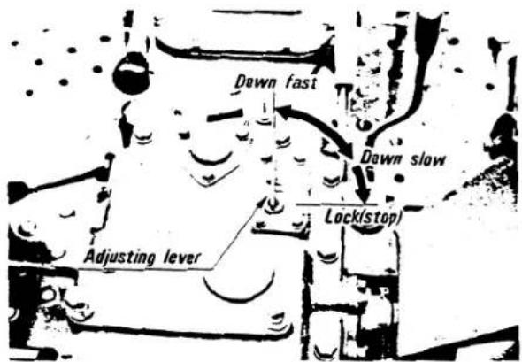
■ Down speed adjusting lever 10
■ Ground PTO gear-shift lever ..... 10
■ PTO clutch control lever 10
■ Front wheel drive lever - DT types ..... 10
■ Main gear-shift lever 11
■ Hi-lo gear-shift lever 11
■ Creep gear-shift lever 11
■ Clutch pedal 11
■ Hydraulic auxiliary control lever ..... 11
INSTRUMENTS AND CONTROLS
1. INSTRUMENT PANEL
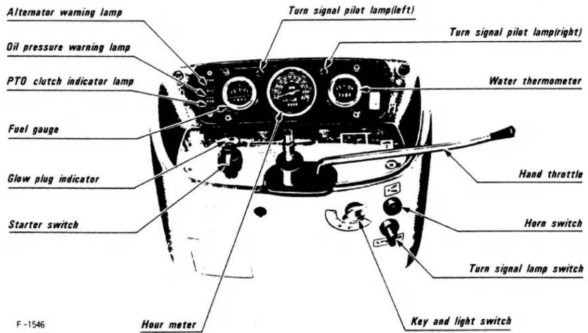
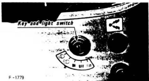
■ Key and light switch
OFF .... All the circuits are open. (Key can be removed) ON .... Engine can be started. All meters and switches are turned on.
① Head lamps on, high beam.
≡D ...... Head lamps dimmed, low beam.
≡D…… Clearance and tail lamps are turned on. (Key can be removed.)

Take the key out when not using the tractor.
■ Starter/preheating switch
(1) Turn the switch to "Preheat", to preheat the combustion chamber.
(2) To start the engine, shift the hi-lo shift-gear lever to neutral, and turn the starter switch to "Start." Take your fingers off the switch, and it will return automatically when the engine starts.
[PRECAUTION]
The engine will not start if the hi-lo gear-shift lever is not in neutral.

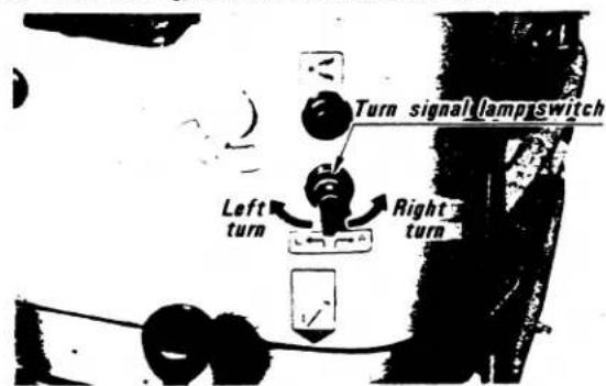
■ Turn signal lamp switch
(1) When the switch is turned on, the turn signal lamps and their pilot lamps on the control panel will blink.
(2) After turning, return the switch to the center.
■ Hour meter
The hour meter shows the engine revolution. PTO shaft revolution and the number of hours the tractor has been used for.
(1) The indicator shows the engine revolution and the corresponding PTO revolution. The red line indicates the standard PTO revolution.
(2) The center of the meter has 5 digits showing the number of hours the tractor has been used (to the nearest tenth.)
■ Water thermometer
This indicates the engine temperature with the key and light switch in the ON position.
[CAUTION]
If the indicator should go over H line, the engine must be stopped until the cause of the overheating is corrected. (Such as quantity of cooling water, fan belt loosening)
(1) After operating the engine, never touch radiator until it has had sufficient time to cool.
(2) Check this water thermometer frequently as you operate.
■ Oil pressure warning lamp (red)
Shows whether the oil pressure in the engine is proper.
(1) The light goes on when the key and light switch is turned on. It goes off when the engine starts and the engine oil starts to circulate normally.
(2) If the light stays on even after the engine starts, immediately stop the engine, and check the cause of the trouble.
It is normal for the lamp to stay on while the engine is rotating at a low speed.
■ Alternator warning lamp (red)
The pilot lamp shows whether the battery is properly charged.
(1) The lamp goes on when the key and light switch is turned on. It goes off when the engine starts and the battery charging system starts to function normally.
(2) If the lamp stays on even after the engine starts, immediately stop the engine, and check the regulator, fuse and relay fuse.
If the trouble cannot be located, contact your Kubota dealer.
■ PTO clutch indicator lamp (red)
The PTO clutch indicator lamp goes on when the PTO clutch is disengaged and goes off when the clutch is engaged.
- CONTROLS

INSTRUMENTS AND CONTROLS
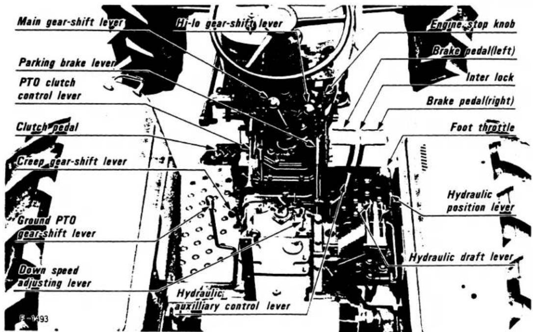
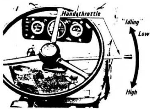
■ Hand throttle
Choose the engine speed most suitable for the job at hand.
* Push forward .... Idling
* Pushed back ...... Maximum speed
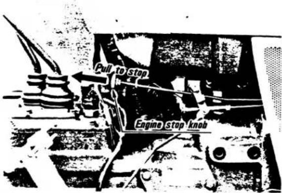
■ Engine stop knob
When the knob is pulled, the fuel supply is cut off and the engine stops.
■ Brake pedals
There are two brake pedals for braking the right and left rear wheels.

When travelling on the road, use the connector to put down both brakes at the same time. Uneven braking may make dangerous sharp turns.
■ Foot throttle pedal
Use the pedal when travelling on the road. Keep your foot off the pedal while idling. Press down on it for higher speed. This pedal is interlocked with the hand accelerator lever; when using the pedal, keep the hand lever in the idling position.
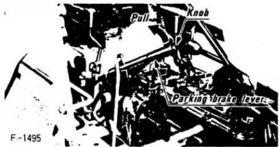
■ Parking brake lever
Pull the hand brake lever to brake.
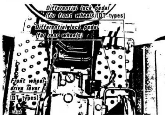
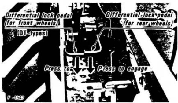
■ Differential lock pedal
If one of the rear wheels should slip, step on the differential lock pedal. Both wheels will then turn together, stopping slippage.
Differential locking is maintained only while the pedal - both pedals on DT types (4-wheel drive) - is (are) depressed.
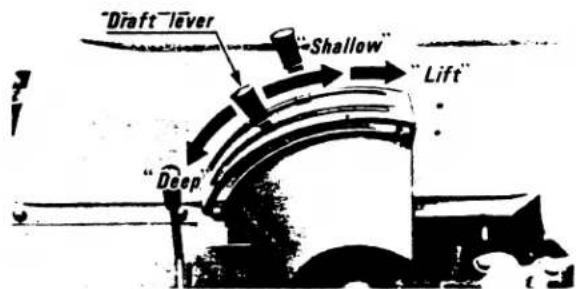
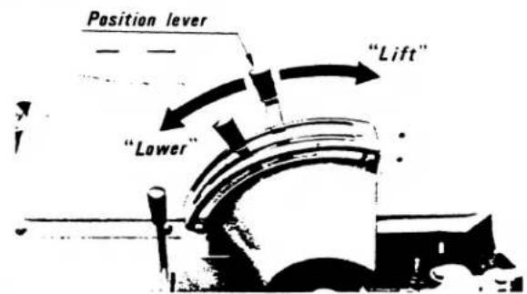
■ Hydraulic draft lever
■ Hydraulic position lever
■ Down speed adjusting lever
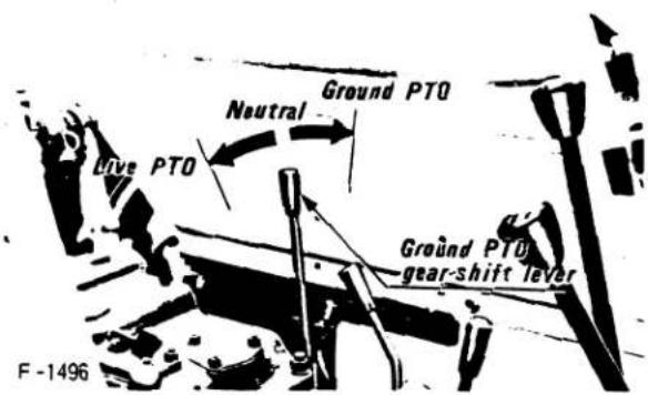
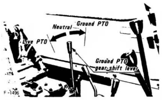
■ Ground PTO gear-shift lever
■ PTO clutch control lever
When the lever is horizontal, the PTO clutch engages. When the lever is lifted, the clutch disengages. When engaging the clutch, lower the lever while pushing it toward the fulcrum.
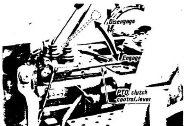
[PRECAUTIONS]
(1) When not using the PTO shaft for long periods of time, keep the lever in the horizontal position so that the clutch is engaged.
(2) Use the lever only when connecting or disconnecting an implement PTO shaft from the PTO shaft. Keep it in the horizontal position with the PTO pilot lamp off during operation and travelling.
(3) To stop PTO shaft rotation, shift the ground PTO gears to neutral.
![KUBOTA M5500 - [PRECAUTIONS] - 1](/content/2026/05/867607/images/094dc71a9aa22c9c00e84e9c99fdeb52180316a463134e3b9440e4111214472b.jpg)
Before making adjustments of an implement, stop the engine or disengage the PTO clutch (PTO lamp turning on).
■ Front wheel drive lever - DT types
(4-wheel drive)
Use the lever for driving the front wheels. Push it forward, and the front wheels will drive. Front wheel drive is effective for the following jobs:
(1) When great pulling force is needed, such as working on a slope or in a wet field, when pulling a trailer, or when working with a front loader.
(2) When working on sands.
(3) When working on a hard soil where a rotary tiller might dash forward.
(4) When entering and leaving a field or going over a bank.
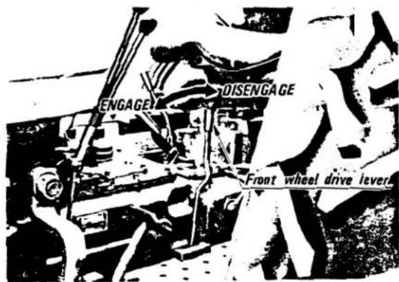
(PRECAUTIONS)
(1) Depress the clutch pedal before engaging the front wheel drive lever.
(2) If the front wheel drive lever is difficult to disengage, turn the steering wheel is either direction, and the lever will disengage completely.
(3) Do not engage the front wheel drive lever while the tractor is travelling on a paved road or travelling at high speed.
Otherwise, the tires may wear down quickly. Or an accident may occur if the tractor is suddenly braked at high speed.
INSTRUMENTS AND CONTROLS
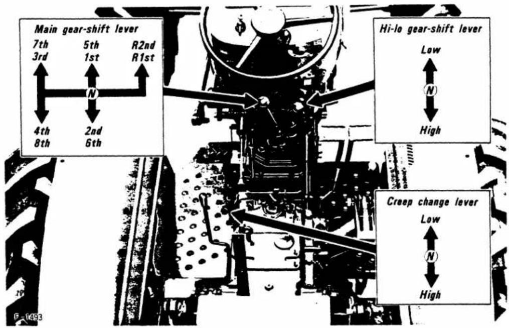
■ Main gear-shift lever
■ Hi-lo gear-shift lever
■ Creep gear-shift lever
By using these three levers in combination, 16 forward speeds and 4 reverse speeds can be obtained.
[PRECAUTION]
Synchro-mesh is provided to all of forward gears. You can always shift the forward gear while the tractor is moving.
[M5500(DT)·M7500(DT)]
■ Clutch pedal
Step on the clutch pedal quickly to disengage the clutch. Raise your foot slowly from the pedal to engage the clutch to avoid damaging the clutch plate.
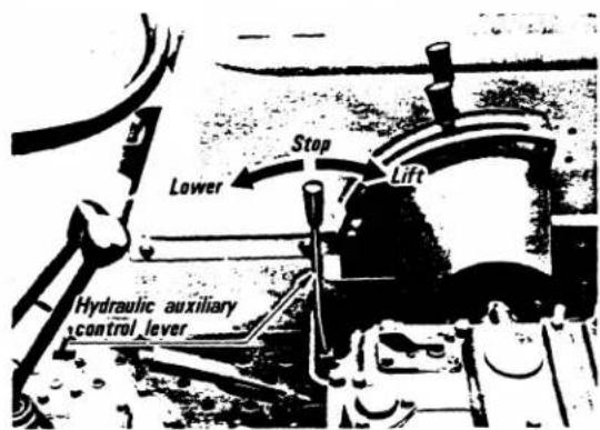
■ Hydraulic auxiliary control lever
OPERATION
- INTRODUCTION 13
- WORLD WIDE GRAPHIC SYMBOLS 13
- BREAK-IN PROCEDURES 13
- PRESTARTING INSPECTION 14
- STARTING AND STOPPING THE ENGINE ..... 14
■ Starting 14
■ Starting the engine in cold weather 14
■ Stopping the engine 14
- OPERATION THE TRACTOR 14
■ Starting 14
■ Stopping.... 14
■ Directions for use of the power steering ..... 14
- PERFORMANCE CHECKS DURING OPERATION ... 15
■ Oil pressure warning lamp 15
■ PTO clutch indicator lamp 15
■ Alternator warning lamp 15
■ Fuel 15
■ Exhaust fumes 15
■ Immediately stop the engine if: 15
- OPERATING THE TRACTOR ON THE FARM ..... 15
■ Differential lock 15
■ PTO operation 16
■ Three-point hitch 16
■ Hydraulic unit 17
■ Hitch points 17
■ Hydraulic control unit use reference chart ..... 18
■ Drawbar 19
■ Parking the tractor 19
■ Towing the tractor 19
- WHEEL ADJUSTMENT 19
■ Front wheels.... 19
■ Rear wheels (Pan type or dish type) 19
-
FENDER ADJUSTMENT 21
-
WEIGHTING THE TRACTOR 21
■ Front bumper weights 21
■ Rear wheel weights....21
1. INTRODUCTION
This section contains information describing the correct operating procedures for all tractor controls and operating mechanisms. Do not operate the tractor until you have read this section carefully and understand its content. If you have any questions, contact your Kubota Dealer.
Throughout this section and the rest of the manual, you will find safety suggestions. These suggestions are intended to insure that no injuries occur while the tractor or attaching implements are being used. PAY ATTENTION TO THESE SAFETY SUGGESTIONS. SAFETY IS NO ACCIDENT.
2. WORLD WIDE GRAPHIC SYMBOLS
The facing page contains a chart showing worldwide graphic symbols which are used to identify operator controls on farm equipment throughout the world. Familiarize yourself with these symbols, many of which are used on the tractor to identify the instruments and controls.
WORLD WIDE GRAPHIC SYMBOLS
 Engine Oil Pressure Engine Oil Pressure |  Water Temperature Water Temperature |  Ammeter or Generator Light Ammeter or Generator Light |  Fuel Fuel |  Slow Speed Range Slow Speed Range |
 Engine R.P.M. Engine R.P.M. |  Raised Raised  Lowered Rockshaft Lowered Rockshaft |  Left RightTurn Signals Left RightTurn Signals |  Extended Retracted Remote Cylinder Extended Retracted Remote Cylinder |  Control Lever Operating Direction Control Lever Operating Direction |
 OnOff Power Take-off OnOff Power Take-off |  Windshield Wiper Windshield Wiper |  Heating Cooling Temperature Control Heating Cooling Temperature Control |  Engage or In Engage or In  Disengage or Out Connection Disengage or Out Connection |  Fuel Shut-off Fuel Shut-off |
3. BREAK-IN PROCEDURES
While the tractor is new, during the first 60 hours of operation, observe the following break-in procedures. Adherence to these procedures will insure longer equipment life.
(1) Allow at least five minutes for engine warm-up before operating the tractor under a load.
(2) Do not operate the tractor at full throttle during the break-in period.
(3) Do not drive the tractor at high speeds.
(4) Avoid sudden starting and stopping.
(5) Change the engine oil and clean the oil filter 35 hours after first use. [M4500 (DT)]
(6) Change the engine oil and clean the oil filter 60 hours after first use. [M5500 (DT) · M7500 (DT)]
(7) Change transmission oil, and clean hydraulic oil filter 60 hours after first use.
(8) Change front axle case oil, front differential gear case oil and front bevel gear case oil 60 hours after first use. [DT-types]
4. PRESTARTING INSPECTION
Prior to starting the engine, always inspect the tractor (see Maintenance or the Lubrication and Service Time Chart).
5. STARTING AND STOPPING THE ENGINE
■ Starting
(1) Always shift the hi-lo gear shift lever to neutral. Otherwise, the safety starter switch will not let the engine start.
(2) Pull the handle throttle halfway out.
(3) Insert the key into the key and light switch, and turn it to "On".
(4) Turn the starter switch to "Start." Release the switch as soon as the engine starts.
[PRECAUTION]
The starter switch can be turned only when the key and light switch is set to "ON" "≡D" "≡D".
![KUBOTA M5500 - [PRECAUTION] - 1](/content/2026/05/867607/images/f8acae8b08fb33dec4e7a97f2d3c8f1f96e940b4cd937de74aada71c07c68440.jpg)
Do not start the engine indoors with poor ventilation. Exhaust fumes may cause gas poisoning.
■ Starting the engine in cold weather
In cold weather, start the engine as explained below.
(1) Follow steps (1) to (3) above.
(2) Turn the starter switch to "Preheat" and warm the engine for 40 seconds.
(3) While depressing the engine stop knob, turn the starter switch to "Start," and the engine will start. If it should fail to start, repeat steps (2) and (3).
[PRECAUTIONS]
(1) If the temperature drops below 5^ F, turn the starter switch to "Preheat" and warm the engine for 60 seconds, before turning the switch to "Start." If the engine does not start 5 to 10 seconds after the switch is turned to "Start," continue this until the engine starts. To protect the battery and the starter, do not leave the starter switch in "Start" position for 30 seconds or more.
(2) Do not use starting fluid to prevent the serious trouble of engine.
■ Stopping the engine
(1) After slowing down the engine, pull back the engine stop knob until the engine comes to a complete halt.
(2) When the engine stops, turn the key and light switch to "Off" to prevent the battery from discharging. To keep the parking lamps on, turn the key and light switch to "≡D" and remove the key.
[CAUTION]
Push the engine stop knob back into its original position after the engine has completely stopped. If the knob is out, the engine cannot be started next time.
6. OPERATION THE TRACTOR
■ Starting
(1) Depress the clutch pedal, and shift the main, hi-lo and creep gear levers to the desired speed.
(2) Accelerate the engine to a proper level.
(3) Lower the hand brake and slowly release the clutch.
[PRECAUTION]
(1) Do not start the tractor with the parking brake on. Trouble may occur.
![KUBOTA M5500 - [PRECAUTION] - 1](/content/2026/05/867607/images/3399d39cc3101a5f9cf342aca4f2bcfa6bdced611d53080cd8dfe809f6226470.jpg)
(1) Sudden release of the clutch may make the tractor dash forward.
(2) Always interlock the right and left brake pedals before travelling on public roads. Uneven braking may result in sharp turns, dangerously tilting the tractor.
(3) Do not take any passengers on the tractor.
(4) Do not drive the tractor close to the edges of ditches or banks which may break under the weight of the tractor, especially when the ground is loose or wet.
■ Stopping
(1) Slow down the engine.
(2) Step on the clutch and brake pedal.
(3) After the tractor has stopped, shift the main, hi-lo and creep gears to neutral, release the clutch pedal, pull the hand brake and apply the parking brake.

(1) Always apply the parking brake when parking the tractor. As this tractor has a constant-mesh transmission mechanism, it may move when the creep gear-shift lever is in "L" or "H", or the hi-lo gear-shift lever is in "Low". This normally happens when (1) the temperature of the transmission oil is high, and (2) the engine revolves at high speeds.
(2) When parking on a slope, put blocks behind wheels, and put on the parking brake.
■ Directions for use of the power steering
(1) Power steering is activated only while the engine is running. Slow engine speeds make the steering wheel a little heavy to handle. While the engine is stopped, the tractor functions in the same manner as other ones without power steering.
(2) When the steering wheel is turned all the way, the relief valve opens and an alarm is produced. Do not drive the tractor with the alarm on for a long time.
(3) Avoid turning the steering wheel while the tractor is stopped, or tires and rims may wear out sooner.
(4) The power steering mechanism makes the steering wheel very easy to handle. Be careful when driving on a road.
7. PERFORMANCE CHECKS DURING OPERATION
While operating your tractor check the following regularly:
(1) WATER TEMPERATURE. If engine temperature gauge needle moves past the H on the gauge, stop the engine and check the following:
- Radiator Coolant level
- The radiator net for clogging due to a build-up of dirt and debris
- Fan belt tension

[CAUTION]
DO NOT REMOVE THE RADIATOR CAP FOR AT LEAST TEN MINUTES AFTER THE ENGINE HAS STOPPED.
(2) OIL PRESSURE. If the oil pressure lamp begins to glow while the engine is running, turn the engine off immediately. This lamp indicates low engine oil pressure. Check the following:
- Engine oil level
- Engine oil lubrication system including the oil pump and oil filtration system.
[CAUTION]
UNDER NO CIRCUMSTANCES SHOULD THE ENGINE BE RUN WHILE THE OIL PRESSURE LIGHT IS GLOWING. IF YOU CANNOT DETERMINE THE CAUSE OF A LOW OIL PRESSURE SITUATION, CONSULT YOUR KUBOTA DEALER.
■ Oil pressure warning lamp
The oil pressure pilot lamp goes on if the oil pressure in the engine goes below the prescribed level. If this should happen during operation, and it does not go off even if the engine is accelerated to more than 1000 rpm (16.7r/s), immediately stop the engine, and check:
(1) The quantity of engine oil (see page 23, 29 Engine oil).
(2) The lubrication system (see page 29 Engine oil filter).
■ PTO clutch indicator lamp
(1) The pilot lamp goes on to show that the PTO clutch lever is in the off position.
(2) The longer the lamp is on, the heavier the load on the clutch spring, clutch bearing and engine. Avoid keeping the PTO clutch lever in the off position for longer than five minutes.
(3) When the PTO shaft is not in use, for example, while travelling, put the PTO control lever into neutral and the PTO clutch lever in the horizontal position to stop the PTO shaft rotation.
■ Alternator warning lamp
This lamp will light if the battery is discharging. If the light should glow while the tractor is running, turn the engine off and check the battery terminals and alternator connections for loose wires.
FUELS. Check the fuel level. If the tractor runs out of fuel, the fuel system must be bled. (See Maintenance section for bleeding instructions.)
■ Fuel
Be careful not to empty the fuel tank. Otherwise air may enter the fuel system. Should this happen, the system should be bled (see page 30 Fuel system maintenance).
■ Exhaust fumes
(1) Exhaust fumes at normal output are colorless.
(2) Exhaust fumes become a little colored when output is increased above the prescribed level, but does not affect tractor power. Excessively dark fumes, however, may indicate trouble.
■ Immediately stop the engine if:
(1) The engine suddenly slows down or accelerates,
(2) Unusual noises suddenly appear,
(3) Exhaust fumes suddenly become very dark,
(4) The oil pressure pilot lamp goes on during operation.
[NOTE]
For checking and servicing of your tractor, contact your nearest Kubota dealer for instructions.
8. OPERATING THE TRACTOR ON THE FARM

(1) The tractor easily tips over when working on a slope. Carefully balance the tractor.
(2) Keep people away from the tractor during operation.
(3) When driving into a field with very high banks, always use a ramp board to avoid tipping the tractor over.
■ Differential lock
Though very useful when used properly, the differential lock is very dangerous if misused, and may cause breakdown. Use the differential lock in the following cases:
(1) If one wheel slips and the tractor cannot go straight up or down a slope.
(2) If one wheel is caught in mud and the tractor cannot go forward.
(3) If the wheels slip during plowing operation.
[PRECAUTIONS]
(1) When using the differential lock, always slow down the engine.
(2) The differential lock automatically releases when the pedal is released. If this does not happen, lightly step on the brake pedals alternately.
![KUBOTA M5500 - [PRECAUTIONS] - 1](/content/2026/05/867607/images/c10b73562351ea5eee8451a909d6adad0a5aa90f44e58a751a9eef83aae276ce.jpg)
Always disengage the differential lock before turning the tractor. It is very dangerous not to do so.
■ PTO operation
By maneuvering the ground PTO gear-shift lever it is possible to select the engine drive (live PTO) or ground drive (ground PTO).
(1) LIVE PTO
Raise the PTO clutch control lever to disengage the clutch. Wait for a few seconds, and then put the ground PTO gear-shift lever into the live PTO position. PTO operation can be done completely independently of travelling. Thus the tractor can be stopped without interrupting PTO operation.
(2) GROUND PTO
Stop the tractor, and put the ground PTO gear-shift lever into the ground PTO position.
【PRECAUTION】
Do not employ the ground PTO for heavy-duty operations such as rotary tilling and forage harvesting.
■ Three-point hitch
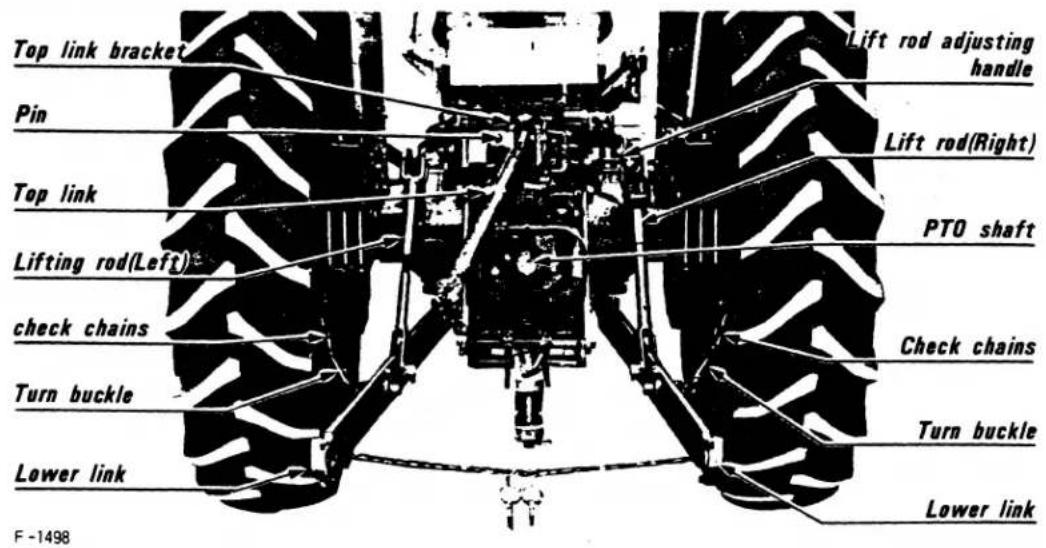
(1) TOP LINK MOUNTING HOLES
Attach the top link to the tractor at one of the three holes referring to the "Hydraulic control unit use reference chart" on page 18. Most sensitive draft control is possible at the top hole which is usually employed for light jobs.
natural_image
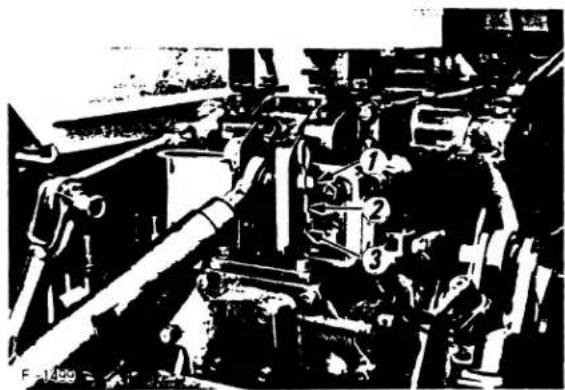
Black-and-white photo of heavy machinery with numbered components (no visible text or symbols)■ Hydraulic unit
The hydraulic unit consists of the lifting system which comprises a hydraulic cylinder and control valve, and the engine drive hydraulic pump and pipe.
(1) LIFTING CAPACITY
Maximum lifting capacity is 3300 lbs. (1500 kg) (at the end of the lower links).
(2) OPERATION
The hydraulic unit can perform the following three types of controls depending on the implement to be used.
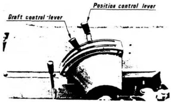
- Position control
Position control is achieved by maneuvering the position control lever with the draft control lever put in the lowest position. This control is used for operations where the hydraulic system is floated.
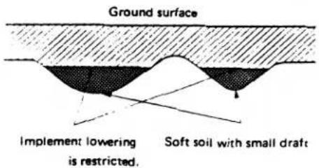
- Draft control
Draft control is achieved by maneuvering the draft control lever.
- Mixed control
In draft control, when draft decreases, the implement automatically lowers to increase draft. However, the implement is sometimes lowered too much. To limit the degree the implement can be lowered, thus increasing working efficiency and achieving good results, position control can be added. This mixed control automatically controls the implement position hydraulically by draft control, and the draft decreases by position control.
■ Hitch points
Implements to be mounted on the tractor must have hitch points as illustrated below for accurate hydraulic operation. Their weight should not exceed 1213 lbs. (550kg).
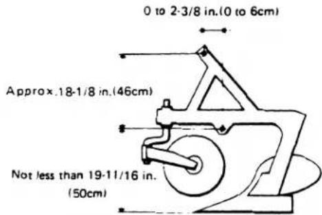
[NOTE]
(1) The dimensions in the example illustrated above should be followed.
(2) While the tractor is travelling with an implement, the implement must be at three hitch points and with the check chains properly tightened.
■ Hydraulic control unit use reference chart
In order to handle the hydraulic unit properly, the operator must be familiar with the following. Though this information may not applicable to all types of implements and soil conditions, it is useful for most general situations.
| implement | Soil quality | Top link mounting holes | Draft control lever | Position lever draft lever | Gauge wheel | Check chains | Remark |
| Bottom plow: | |||||||
| One-bottom(ordinary or rollover).... | Light soil | 3 or 2 | No | Adjust the check chains so that the implement can move 5 to 6cm laterally. | |||
| Medium soil | 3 or 2 | ||||||
| Heavy soil | 2 or 1 | ||||||
| Two-bottom(ordinary or rollover).... | Light soil | 1 | No | ||||
| Medium soil | 3 or 2 | ||||||
| Heavy soil | 2 or 1 | ||||||
| Three-bottom .... | Light soil | 1 | Mixed control or draft control | No | Check chains should be tight enough to prevent excessive implement movement when implement is in raised position. | ||
| Medium soil | 3 or 2 | ||||||
| Heavy soil | 2 | ||||||
| Disc plow: | |||||||
| Two-bottom(ordinary or rollover).... | - | 2 | No | ||||
| Three-bottom .... | - | 1 | No | ||||
| Harrower (spike, springtooth, disc type) .... | - | 1 | No | ||||
| Sub-soiler .... | - | 1 | No | ||||
| Ditcher .... | - | 1 | No | ||||
| Weeder, ridger .... | - | 1 | Yes | Tighten | Put the position control lever in the lowest position during operation. | ||
| Earth mover, digger, scraper, manure fork, rear carrier .... | - | 1 | Position control | Yes/No | Tighten | With implements with gauge wheels, lower the position control lever all the way. | |
| Mower (mid- and rear-mount type) | |||||||
| Hay rake, tedder .... | - | 1 | No | Tighten | |||
![KUBOTA M5500 - [NOTE] - 1](/content/2026/05/867607/images/9a609cd095bb9a369297f2a97d2b8becfb660b7a88b89fe07f09689c00844f07.jpg)
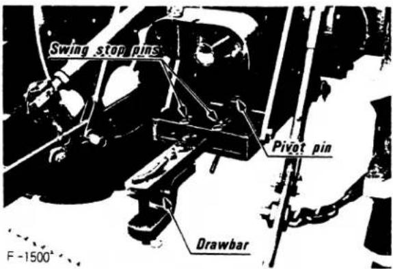
Drawbar
The tractor is equipped with a swinging drawbar. The adjustment on the drawbar combined with the adjustment on most pull-type implements should give you sufficient control of draft to minimize wheel slippage and control front-end lift. The drawbar may be allowed to swing or may be held stationary by the placement of the pins in the drawbar carrier.
To make lengthwise adjustment in the drawbar the pivot pin located underneath the tractor differential housing must be removed. With the pin removed the drawbar may be repositioned and the pivot pin installed into the desired pivot hole.
A cross drawbar may be fitted to the three point hitch. When a cross drawbar is used, the position control lever the hydraulic control quadrant should be used.
[CAUTION]
DO NOT ATTACH ANY IMPLEMENT, PULL-CHAIN OR ROPE TO ANY POINT ON THE TRACTOR ABOVE THE CENTER LINE OF THE REAR AXLE.
■ Parking the tractor

When parking the tractor, lock the brake pedals together and set the parking brake. Leave the tractor in gear if your are parking on an incline. For additional safety, place a large block of wood or a stone underneath one rear wheel to prevent the tractor from rolling unexpectedly.
■ Towing the tractor
Do not tow the tractor at speeds faster than the tractor would travel under its own power. Towing the tractor at high speed may make the tractor difficult to handle and can result in serious tire damage.

When towing or pulling the tractor do not attach a tow line to any point above the center line of the rear axle. Attachment of a tow line above the center line of the rear axle may cause the tractor to tip over backwards.
9. WHEEL ADJUSTMENT
■ Front wheels
Tread is adjusted at 50-3/8 in. (M4500·M5500)/53-7/8 in. (M7500) at shipment.
(1) Lift the front of the tractor with a jack.
(2) Remove the front axle mounting bolts and the tie-rod mounting bolts.
(3) Move the front axles (right and left) to the desired position, and tighten them with bolts.
(4) Adjust the toe-in.
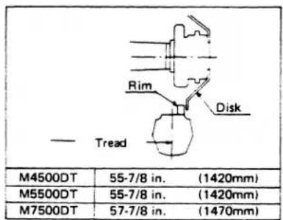
■ Rear wheels (Pan type or dish type)
The rear wheels can be adjusted to different settings. To adjust the rear wheels lift the rear of the tractor with a jack. Select the width desired and, if necessary, remove wheel center from rim. Remount the rim to relocate the tire center and attach wheel to the tractor. Check to see that the tire is turning in the proper direction as indicated by the arrow on the side of the tire. Rear wheel weights can be attached to the rim at any tread setting.
FRONT WHEEL ADJUSTMENT CHART
[DT-types]
[Standard-types]
| (1) Tread | (2) Tread | (3) Tread | ||||
| M4500 | 50-3/8 in. | (1280mm) | 54-5/16 in. | (1380mm) | 58-1/4 in. | (1480mm) |
| M5500 | 50-3/8 in. | (1280mm) | 54-5/16 in. | (1380mm) | ||
| M7500 | 53-7/8 in. | (1370mm) | 57-7/8 in. | (1470mm) | 61-13/16 in. | (1570mm) |
| (4) Tread | (5) Tread | (6) Tread | ||||
| M4500 | 62-3/16 in. | (1580mm) | 66-1/8 in. | (1680mm) | 70-1/16 in. | (1780mm) |
| M5500 | 58-1/4 in. | (1480mm) | 62-3/16 in. | (1580mm) | 66-1/8 in. | (1680mm) |
| M7500 | 65-3/4 in. | (1670mm) | 69-11/16 in. | (1770mm) | 73-5/8 in. | (1870mm) |
| (7) Tread | (8) Tread | 【CAUTION】 THE WIDTH OF THE TREAD FOR THE FRONT LOADER SHOULD NOT BE GREATER THAN 59 INCHES (1500 mm) | ||||
| M4500 | 74 in. | (1880mm) | 78 in. | (1980mm) | ||
| M5500 | 70-1/16 in. | (1780mm) | 74 in. | (1880mm) | ||
| M7500 | 77-1/2 in. | (1970mm) | ||||
REAR WHEEL ADJUSTMENT CHART
| (1) Disk Rim Tread - | (2) Tread - | (3) Tread - | (4) Tread - | ||||
| M4500 (DT) | 51-3/16 in. (1300mm) | 55-1/8 in. (1400mm) | 59-1/16 in. (1500mm) | 63 in. (1600mm) | |||
| M5500 (DT) | |||||||
| M7500 (DT) | |||||||
| (5) Tread - | (6) Tread - | (7) Tread - | |||||
| M4500(DT) | 66-15/16 in. (1700mm) | 70-7/8 in. (1800mm) | 74-13/16 in. (1900mm) | ||||
| M5500(DT) | |||||||
| M7500(DT) | |||||||

FUEL AND LUBRICANT SPECIFICATIONS
- FUELS 23
■ Fuel specifications .... 23
■ Fuel storage 23
■ Filling the tractor fuel tank ..... 23 - LUBRICANTS 23
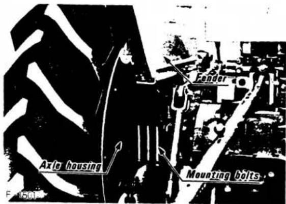
10. FENDER ADJUSTMENT
The fenders may be adjusted in and out with the wheels. To adjust the fenders, loosen the fender mounting nuts which are located on the bottom of the axle near the check chain brackets. Relocate the fender making sure there is sufficient clearance between the fender and tire. When the fender is adjusted correctly the fender mounting bolts should be in one of the slots cast into the axle housing. With the fender in the desired position tighten the mounting nuts.

[CAUTION]
The fenders are designed to prevent loose material from flying up and striking the driver and to shield the driver from the turning tire. Keep the fenders properly adjusted and keep the fender mounting bolts tight. Under no circumstances should anyone be allowed to ride on the tractor while sitting on the fenders.
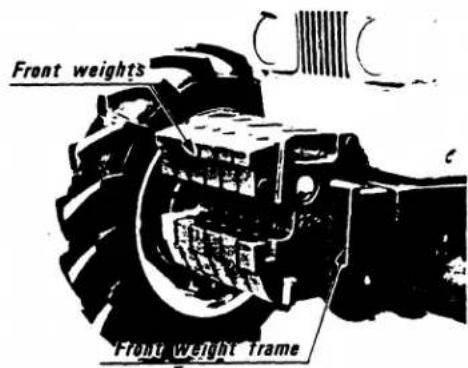
11. WEIGHTING THE TRACTOR
■ Front bumper weights
It may be necessary to mount front bumper weights on the tractor if the tractor is to be operated with heavy three point mounted or drawn implements. A front weight frame and KUBOTA suitcase weights are available from your KUBOTA Dealer. Your dealer can help you decide how much weight is required for your particular application.
F-1502
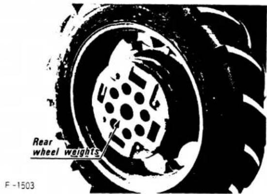
■ Rear wheel weights
Rear wheel weights may be mounted on the rear wheels. Consult your Kubota dealer for the correct weight necessary for your particular application.
FUEL AND LUBRICANT SPECIFICATIONS
1. FUELS
Always use quality fuel. Be sure the fuel is clean, completely distilled, well-refined and free of water. This is extremely important as the engine fuel injection system is designed with very close tolerances. Dirt and moisture can clog or damage the fuel system.
In order to assure that the fuel is acceptable quality, it is recommended that you purchase your fuel from a reputable dealer selling a known brand of fuel. A few cents saved on less expensive fuel could quickly be lost if repairs to the fuel system are required as a result of using inferior fuel.
■ Fuel specifications
For most applications, diesel fuel number 2 (no. 2D) should be used. Diesel fuel no. 2 is a heavier fuel and produces more work (or energy) per gallon than diesel no. 1. Recommended fuel depends on ambient air temperature and altitude. When operating in temperatures below 20^ (-6.6^) or at altitudes above 5000 feet (1,524m) use diesel fuel no. 1. For all other applications use diesel fuel no. 2.
Your KUBOTA tractor will operate best on fuels with the following specifications:
(1) Less than 1.0% sulphur content in the fuel, preferably less than 0.5%.
(2) Water content should not exceed 0.10%.
(3) In cold weather operating conditions where number 1 diesel is used the fuel should have a pour point at least 10 degrees below the lowest ambient air temperature.
■ Fuel storage

[CAUTION]
If spilled, diesel fuel will not evaporate. Clean up all spills or they will collect dirt and dust. Diesel fuel is flammable. Keep open flames away from fuel and fuel storage facilities.
It is often desirable to store large quantities of fuel at your farm or place of business. It is important to keep this fuel free of dirt and excess moisture during storage. Fuel should be stored in black iron tanks or containers. Do not store diesel fuel in galvanized tanks. The zinc coating on the tank will react with the fuel forming compounds which may damage the tractor fuel system.
If you store large quantities of fuel, the storage tank should be positioned so that the rear of the tank lies well below the point from which the fuel is drawn. A tilted tank allows sediment and water to settle away from the pour point. In addition it is recommended that our storage tank be equipped with a drain plug located at the lowest point on the tank so that water and sediment may be drained off periodically.
After filling your fuel storage tank allow the fuel to settle for at least twelve hours. This will allow the suspended sediment in the fuel to collect at the low point in the tank. Keeping the fuel tank as full as possible at all times will prevent the build-up of excess moisture in the stored fuel.
Whether you use a pump type or gravity feed type fuel transfer system, an in line filter should be installed in the system as added protection to prevent dirt and water from entering the tractor fuel system.
If you store your fuel in a 55 gallon drum, follow the instructions above. Never tip the barrel to get to the residue fuel left in the bottom.
■ Filling the tractor fuel tank
The fuel tank on the KUBOTA tractor is located between the instrument panel cowling and the engine firewall. The fuel tank design incorporates a built-in removable plastic fuel screen. This screen acts to filter out dirt and sediment and should be kept in place at all times when filling the fuel tank. When the fuel filter screen becomes dirty, it may be removed from the tank and washed with clean fuel. Be sure this screen is clean before filling the fuel tank.
Fill the fuel tank at the end of the day. A full fuel tank will minimize moisture build-up from condensation and help to protect the fuel system from corrosion and dust build-up.
Fuel tank Capacity: 14.3 gallons (54 ℓ)
2. LUBRICANTS
Adherence to suggested lubrication frequencies and the use of recommended lubrication oils and greases will assure, more than any other single factor, long and trouble-free service from your tractor. Read this section carefully to familiarize yourself with the lubrication requirements of your tractor.
(1) ENGINE OIL
Oil used in the engine should have an American Petroleum Institute (API)/SAE Classification of service CD. The chart below shows the correct weight oil to be used at various temperature conditions:
| Below 32°F | SAE10W or 10W-30 |
| Between 32° and 77°F | SAE20 or 10W-30 |
| Above 77°F | SAE30 or 10W-30 |
(2) TRANSMISSION OIL
The oil used to lubricate the transmission is also used as hydraulic fluid. To insure proper operation of the hydraulic system and complete lubrication of the transmission it is important that only recommended oils be used in this system. The following are recommended oils, by brand name, that may be used in the transmission hydraulic system.
| Allis Chalmers | 821 Power Fluid |
| Atlantic Richfield (Arco) | Arco Tractor Fluid |
| Case | TCH |
| Chevron | Tractor Hydraulic |
| Exxon | Torque Fluid 56 |
| Ford | M2C41 Tractor Hydraulic Oil |
| International | Hy Trans |
| John Deere | 303, J14C |
| Massey | M1127 Fluid |
| Penzoil | Hydra-Trans and Wet Brake |
| Phillips | H. T. Fluid |
| Shell | Donax T-4 |
| Texaco | T. D. H. Oil |
| Union | Hydraulic/Tractor Fluid |
| Valvoline | Uni-Trac |
(3) POWER STEERING
The power steering system uses SAE 80/90 weight oil.
(4) FRONT WHEEL BEARINGS [Standard-types]
Lubricate the front wheel bearings with SAE lithium based grease.
(5) STEERING GEAR BOX
Lubricate the steering gear box with SAE 80/90W gear oil.
(6) CHASSIS GREASE FITTINGS
Lubricate the chassis grease fittings with lithium based grease. For location of chassis lubrication points see service section of this manual.
(7) FRONT WHEEL DRIVE UNIT [DT-types]
Lubricate front differential and bevel gears with SAE 80/90 weight gear oil.
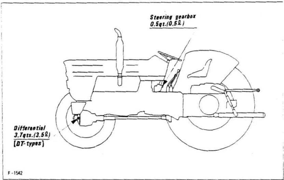
(8) LUBRICANT CAPACITY CHART
| Component | Capacity | ||
| M4500(DT) | M5500(DT) | M7500(DT) | |
| Engine crankcase | 13.4 qts.(12.7 l) | 10.4 qts.(9.8 l) | 12.5 qts.(11.8 l) |
| Transmission hydraulic system | 47.6 qts. (45 l) | ||
| Power steering system | 2.1 qts. (2 l) | ||
| Steering gearbox | 0.5 qt. (0.5 l) | ||
| Front wheel drive unit [DT-types] | |||
| Differential | 3.7 qts. (3.5 l) | ||
| Bevel gears | 0.8 qt. (0.8 l) | ||
| Front axles | 3.7 qts. (3.5 l) | ||
![Engine crankcase M4500(DT)13.4qts.(12.7Ω) M5500(DT)10.4qts.(9.8Ω) M7500(DT)12.5qts.(11.8Ω) Transmission hydraulic system 47.6qts.(45Ω) Bevel gears 0.8qt.(0.8Ω) [DT-types] Front axles 3.7qts.(3.5Ω) [DT-types] Power steering system 2.1qts.(2Ω) F-1542](/content/2026/05/867607/images/588231565a6139a0511f6b6296280e6998391810b06b1823cb3172f8a0ac5a16.jpg)
(9) STORING LUBRICANTS
Store lubricants in a clean, dry area. When handling lubricants, use clean containers that are free from moisture and dust. Use of contaminated lubricants in the tractor will shorten machine life.
MAINTENANCE
- BREAK-IN PROCEDURE 27
- LUBRICATION INTERVALS DURING BREAK-IN PERIOD . 27
■ Engine oil 27
■ Transmission/hydraulic system oil. 27
- OTHER CHECKS DURING BREAK-IN PERIOD 27
- SERVICE AND LUBRICATION INTERVALS 27
- PERIODIC SERVICE PROCEDURES 27
■ Cleaning the air filter 27
■ Washing the air filter element 28
■ Inspecting the air filter 28
■ Changing engine oil 29
■ Checking the engine oil level 29
■ Changing the engine oil filter 29
- FUEL SYSTEM MAINTENANCE 30
■ Fuel filter 30
■ Fuel system bleeding procedure 31
■ Fuel injection pump 32
- TRANSMISSION/HYDRAULIC SYSTEM MAINTENANCE.... 32
■ Changing transmission/hydraulic oil 32
■ Cleaning the transmission/hydraulic system oil filter ..... 32
- COOLING SYSTEM 33
■ Flushing the cooling system 33
■ Cleaning the radiator net 33
■ Antifreeze 34
■ Repairing radiator leaks 34
■ Radiator hoses (Water pipes) 34
- ELECTRICAL SYSTEM 34
■ Battery 34
■ Alternator and voltage regulator 36
■ Alternator and voltage regulator servicing procedures ..... 36
■ Starter 36
■ Fuses 36
■ Protected circuits 37
- FAN BELT ADJUSTMENT 37
- PERIODIC SERVICE SCHEDULE 38
- BATTERY TROUBLE SHOOTING 39
- ENGINE TROUBLE SHOOTING 40

Routine maintenance is based on operating hours as indicated by the engine hour meter located on the face of the tachometer. The hour meter shows the accumulated operating time for the engine. The hour meter is designed to register one hour of operating time for each hour of engine operation at 2200 RPM. Engine operation at less than 2200 rpm will result in an hour meter reading that is proportional to engine speed.
1. BREAK-IN PROCEDURE
Please refer to the operations section of this manual for operating instructions during break-in period.
Maintenance procedures during the break-in period consist of an engine oil and filter change at 35 hours and a transmission/hydraulic oil and filter change (and if your tractor is equipped with four wheel drive an oil change of the front differential oil) at 50 hours.
Since the tractor is new and you are unfamiliar with the operation of the machine it is suggested that you make careful visual inspections of the entire machine prior to operating the tractor during the break-in period.
2. LUBRICATION INTERVALS DURING BREAK-IN PERIOD
■ Engine oil
Change the engine oil and engine oil filter at the end of 35 hours of operation. If it becomes necessary to add engine oil during the break-in period add correct wt. oil.
■ Transmission/hydraulic system oil
Change the transmission/hydraulic oil and oil filter at the end of the first fifty (50) hours of operation. If it becomes necessary to add large quantities of oil to the transmission/hydraulic system prior to the first oil change, drain all oil in the system and replace with new oil of specified weight and grade.
3. OTHER CHECKS DURING BREAK-IN PERIOD
Check the following during the break-in period (first sixty hours of operation).
(1) Tighten all wheel lug bolts after the first eight hours of operation. If the tractor is equipped with a front loader, check the front lug bolts for tightness every forty (40) hours of operation throughout the operating life of the tractor.
(2) Tighten the mounting bolts on the front and rear wheel weights, the front weight frame and front weights after the first eight hours of operation.
(3) Check the tractor daily for water or oil leaks.
(4) Make sure tractor is greased. Be sure you are familiar with all chassis grease points. See the lubrication and service time chart for location of lubrication points.
(5) Check all oil levels twice daily. Add oil if necessary.
(6) Observe the instruments at regular intervals during operation.
4. SERVICE AND LUBRICATION INTERVALS
Recommended service and lubrication intervals are based on service requirements for a tractor being used under average operating conditions. If your tractor is being operated under severe operating conditions (such as extreme dusty conditions, frequent starting and stopping of the engine, operation in extreme temperature conditions, etc.) it may be necessary to perform various service procedures more frequently than is recommended. Under no circumstance should the suggested service intervals be extended beyond those recommended in this manual.
Careful adherence to the suggested service procedures and service schedules will insure trouble-free and safe machine operation and promote machine longevity.
5. PERIODIC SERVICE PROCEDURES
■ Cleaning the air filter
The KUBOTA tractor is equipped with a dry element air filter. The air filter is located in front of the radiator behind the sheet metal grille at the front of the tractor.
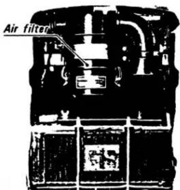
The air filter element should be cleaned on a regular basis. The frequency of cleaning should correspond with the severity of the conditions under which the tractor is being operated; that is, the filter must be cleaned frequently if the tractor is being operated in extremely dusty conditions.
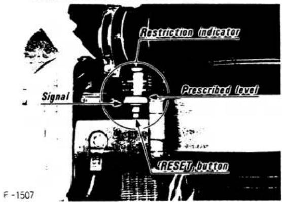
The air filter is equipped with a restriction indicator which, through the use of a colored indicator, indicates when the filter is clogged and in need of cleaning. Whenever the bright orange indicator comes into full view, the air filter element must be cleaned immediately. Other indicators of a clogged air filter are the loss of engine power, excessive exhaust smoke and increased fuel consumption. If the tractor displays any of these operating characteristics, stop the engine immediately and check the air filter.
AIR FILTER RESTRICTION INDICATOR
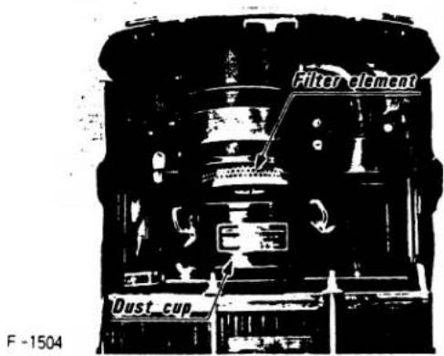
To service and clean the air filter element, remove the front grille to gain access to the filter element cannister. Loosen the retaining ring on the cannister and remove the dust cup on the bottom of the cannister. The air filter is held in position by a wing nut. Remove the wing nut and pull the filter element out.
To clean the element, first shake off loose dirt by tapping the element casing against the palm of your hand. Compressed air may be used to clean the element but care must be taken not to damage the paper element with excessive air pressure. When using compressed air, always blow from the inside of the filter out.
■ Washing the air filter element
In the event compressed air and light tapping of the air filter element do not clean the element sufficiently, the element can be washed. Before washing the element, remove as much dirt as possible with compressed air. To wash the element, soak the filter in warm water and cleaning solution. Rinse the element from the inside with clean water to remove all dirt. Allow the filter to dry completely before reusing.

[CAUTION]
Do not operate the tractor with the air filter removed or with a damp air filter element.
■ Inspecting the air filter
With a flashlight or unshaded lightbulb, take the cleaned filter element into a cark room or closet. Place the light inside the filter element and rotate the element looking for shafts of light that indicate that there are holes in the element paper. If there are any holes in the element the element must be replaced. Before reinstalling the filter element check the rubber sealing gasket on the end of the element. If this gasket is damaged the filter element must be replaced.
[CAUTION]
The air filter element is designed to protect the tractor engine from damaging dust. Failure to clean the filter may result in engine damage. Keep your engine running well. Keep the air filter clean!
■ Changing engine oil.
The engine oil must be changed every 150 hours of operation. Before changing the engine oil run the engine until it is warm. Turn the engine off.
Place an oil catch pan under the crankcase. Remove BOTH crankcase drain plugs and allow all the engine oil to drain from the engine. Replace BOTH drain plugs and refill the crankcase with new oil of appropriate weight for your operating conditions (see the chart below for oils to be used under various operating conditions). Do not start the engine until the oil filter has been replaced.
CRANKCASE DRAIN PLUG
![[M4500(DT)] Drain plugs [M5500(DT)] [M7500(DT)] Drain plug F-1508](/content/2026/05/867607/images/6b8cd402b8fb7587636577839ea6b01561fe657a7ba5445b3f7b63ca5cd1eb53.jpg)
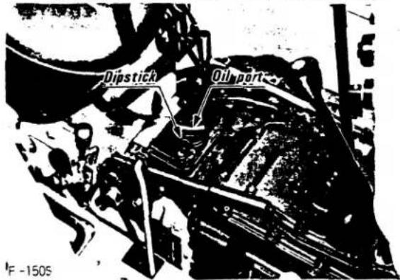
CRANKCASE OIL FILL PORT
![[M4500(DT)] Oil port [M5500(DT)] [M7500(DT)] Oil port](/content/2026/05/867607/images/57c7999b14c2874a05fe9109a4edfeb1ca80aa9ff15428a75e770a8564aef746.jpg)
ENGINE OIL VISCOSITY CHART
| Oil used in the engine should havean American Petroleum Institute(API)/SAE Classification of service CD. | |
| Average temperature | Recommended oil |
| Below 32°F | SAE10W or 10W-30 |
| Between 32° and 77°F | SAE20W or 10W-30 |
| Above 77°F | SAE30W or 10W-30 |
■ Checking the engine oil level
To check the engine oil level, first remove the right hand engine safety screen. Remove the dipstick and check the oil level. If the oil level is below the bottom mark on the dipstick, add oil to the crankcase through the oil fill port until the crankcase is full. If it is necessary to add oil, be sure to add only oil of the same brand and weight as that in the crankcase. Never mix oils of different weights or brands.
![[M4500(DT)] Engine oil dipstick [M5500(DT)] [M7500(DT)] Engine oil dipstick](/content/2026/05/867607/images/4383c88f31f6a922365b297580fbb6375ab3c4c93c5aa53c47713d8382496a32.jpg)
■ Changing the engine oil filter
[M4500(DT)]
(1) Remove the oil filter (2) from the engine to replace elements. Disassemble and reassemble the filter correctly referring to the photo below.
12) If the oil filter is badly stained, remove it carefully so as not to scratch the relief valve and the pressure regulator valve. Clean it well and replace.
(3) The engine oil level will decrease by the amount of oil which flows into the oil filter (2) after its reassembly and reattachment to the engine. It is thus necessary to fill the filter with engine oil before reattaching it to the engine. It is also necessary after reattaching it to run the engine to check for any trouble with engine parts and hydraulic pressure, and to see if the engine oil reaches the prescribed level, after the engine stops, and add oil if necessary.
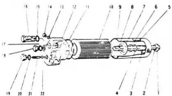
Oil Filter (2)
(1) Center pipe
(2) Center pipe packing
(3) Element spring
(4) Washer (small)
(5) Name plate
(6) Felt packing
(7) Washer (large)
(8) Cir-clip
(9) Body
(10) Oil strainer element
(11) Oil strainer cover packing
(12) Oil strainer cover
(13) Packing
(14) Plug (small)
(15) Pressure regulator
valve packing
(16) Relief valve
(17) Packing
(18) Plug (large)
(19) Escape valve plug
(20) Packing
(21) Escape valve spring
(22) Escape valve
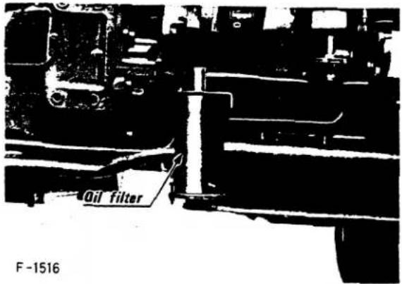
[M5500(DT)]
[M7500(DT)]
The oil filter used is a cartridge type. If it becomes clogged, the by-pass valve is actuated (1.2 to 1.6kg/cm²) to calculate oil. However, oil is not filtered, and trouble may occur. Be sure to replace cartridges every two oil changes or within 400 hours.
6. FUEL SYSTEM MAINTENANCE
■ Fuel filter
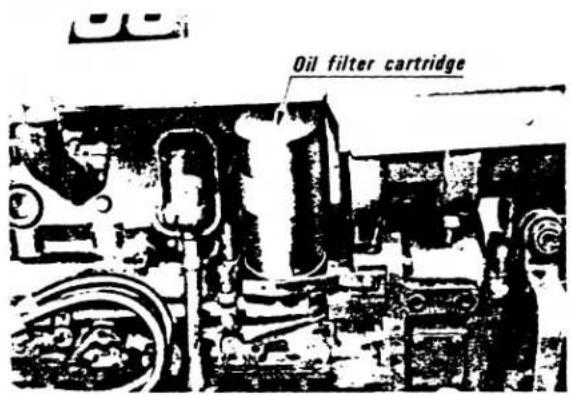
(1) REPLACING THE FUEL FILTER
The fuel filter should be replaced every 200 hours of operation. Use of contaminated fuel may require more frequent fuel filter replacement. To replace the fuel filter, close the fuel petcock at the fuel tank. Using the filter wrench provided with the tractor, unscrew and remove the filter. Install a new filter and tighten the filter by hand only. Open the fuel tank petcock and bleed the fuel system to remove trapped air. Run the engine and check for fuel leaks.

![[M4500(DT)] Fuel filter F -1549](/content/2026/05/867607/images/828fa3d8983463400c868638f68e7cb4dd580cf444611c5d9f85fdc67beff38c.jpg)
![[M5500(DT)] Fuel filter C 1674](/content/2026/05/867607/images/8ed94a01d76fe256bf6f1e8525bee56538c39403095e2b711aec57ee94bd1afe.jpg)
![[M7500(DT)] Fuel filter F-1912](/content/2026/05/867607/images/b175cad4926206075413532b946fc247a5971a265c1a7c978ba6553ef92cf3d1.jpg)
■ Fuel system bleeding procedure
Air must be removed;
(1) when the fuel filter and piping are removed,
(2) when fuel is used up, and
(3) after the tractor has not been used for long periods of time.

Stop the engine before air bleeding.
[PROCEDURE]
[M4500(DT)]
(1) Fill the fuel tank with fuel, and open the fuel cock. (2) Loosen the air vent plug at the top of the filter with two turns.
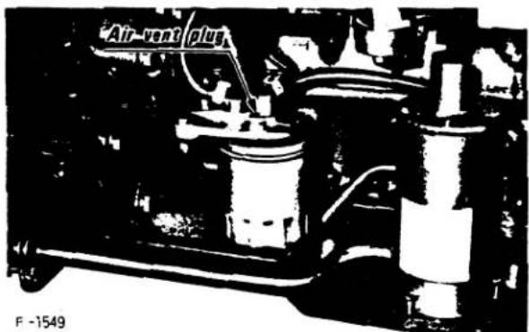
(3) When bubbles disappear from fuel coming out of the plug, twist it back.
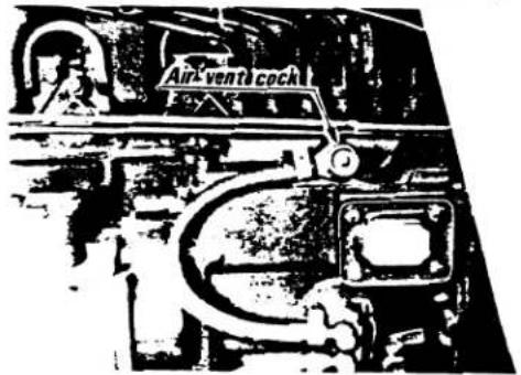
(4) Open the air vent cock on the fuel injection pump.
(5) Pull the engine stop knob to stop the engine, and start the cell motor for about 10 seconds.
[CAUTION]
Always pull out the engine stop knob before starting the cell motor.
(6) Close the air vent cock.
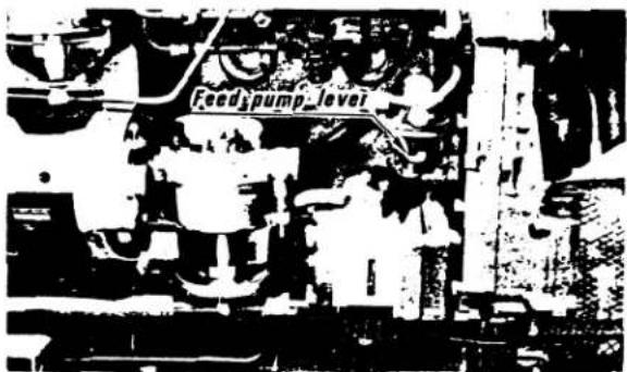
[M5500(DT)] [M7500(DT)]
(1) Fill the fuel tank with fuel, and open the fuel cock.
(2) Check to see if fuel is being supplied by moving the feed pump lever vertically. Judge from the fuel flow and the response of the lever. If no fuel is being fed, turn on the starter switch for a second, and turn the crank shaft a little.
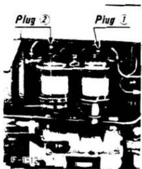
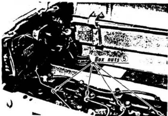
(3) Loosen the plug 1 2 3 4 by about two turns and the four box nuts 5 on the nozzle side of the fuel injection pipes, and pressure-feed fuel using the pump lever.

[M5500(DT)]
[M7500(DT)]
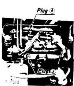
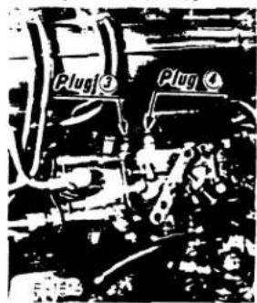
(4) First, when bubbles disappear from fuel coming out of the plug 1. twist it back.
Next, bubbles disappear from fuel coming out of the plugs 2 3 4 , twist it back.
(5) Put the accelerator lever at the maximum speed position with the engine stop knob pushed in, turn on the starter switch to start the engine. Hold until bubbles come up with force around the box nuts, and then stop the engine and tighten the nuts.
(6) Then the engine is prepared for starting, and put the accelerator lever at minimum speed position with engine stop knob pushed in, turn on the starter switch to start the engine. Hold until bubbles come up around the plug 43 , and then stop the engine and twist it back.
(7) Start the engine in the ordinary manner. At this point, do not return the accelerator lever to "Idling", but keep reviving up the engine to exhaust a small portion of air left in the fuel system.
If air still remains and the engine stops even after the above steps, repeat bleeding at plug 2 → plug 3 → box nuts 5 → plug 4.
![KUBOTA M5500 - [M5500(DT)] [M7500(DT)] - 7](/content/2026/05/867607/images/ad7e594df3ef71f6f8a397bdd7e739ad02ea367f42f3f2054f52d23bc5ea1f4f.jpg)
[CAUTION]
Always pull the engine shut-off knob before attempting to turn the engine over while bleeding the tractor fuel system.
■ Fuel injection pump
For service of the tractor fuel injection pump, see your Kubota Dealer.
7. TRANSMISSION/HYDRAULIC SYSTEM MAINTENANCE
■ Changing transmission/hydraulic oil
The transmission/hydraulic system oil must be changed every 600 hours. To drain the transmission/hydraulic oil, place an oil catch pan underneath the transmission. Remove BOTH oil drain plugs from the bottom of the transmission case. Allow all the oil to drain out. Replace the drain plugs. Refill the system through the transmission oil fill port. Fill to the top mark on the transmission dipstick.
TRANSMISSION DRAIN PLUGS
![[Standard-types] Drain plugs F-1551](/content/2026/05/867607/images/987f3d00f03497d20d65a7ce61dc703f414bff92adb41d03cb07152e668288fa.jpg)
![[DT-types] Drain plugs F-1515](/content/2026/05/867607/images/bd52db0f5f9bc9f7c420c5b7d191ebcb8228568915384b49240050b0aab22c5a.jpg)
TRANSMISSION OIL FILL PORT AND DIPSTICK
[CAUTION]
Use only those oils listed in the lubrication section of this manual in the transmission/hydraulic system. Use of other oils may damage the transmission or hydraulic system.
■ Cleaning the transmission/hydraulic system oil filter
The transmission/hydraulic system oil filter must be cleaned every 200 hours. This filter is located on the right side of the engine just to the rear of and slightly above the engine oil filer.
Place an oil catch pan under the filter. Remove the three filter plate retaining nuts and the filter retaining plate.
Remove the filter element and clean thoroughly with kerosene. Clean the magnetic filter and wipe out the inside of the filter case with a clean cloth. Allow the filter to dry thoroughly before it is replaced. If the filter is torn or otherwise damaged, it must be replaced. With the filter reinstalled and all three filter retaining plate nuts secured, run the engine and check for oil leaks. Check the transmission/hydraulic system oil level after the engine has been run. Fill as necessary.

[CAUTION]
The hydraulic system operates by pumping oil at extreme pressure. If a leak develops in a hydraulic line or fitting it may be almost invisible. If you suspect that there is a hydraulic leak in a line or fitting, do not place your hand or arm near the suspected leak. Use a piece of cardboard or wood held near the suspected leak to show the exact location of the leak. Hydraulic fluid is pumped at sufficient pressure to penetrate the skin and enter the blood stream causing serious personal injury. If you suspect you have been injured by escaping hydraulic fluid see a doctor at once.
8. COOLING SYSTEM
To insure proper operation of the engine colling system, the cooling system must be flushed annually or every 800 hours, whichever comes first.
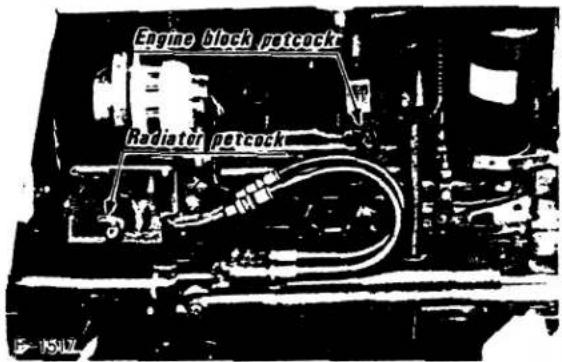
■ Flushing the cooling system
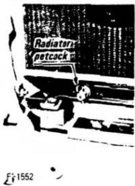
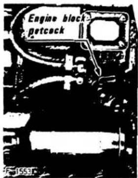
To flush the cooling system, run the engine until it reaches normal operating temperature. Stop the eigine, loosen the radiator cap and drain all the coolant from the system by opening the petcocks on the radiator and engine block. The radiator petcock is located on the bottom front of the radiator. The engine petcock is located on the right side of the engine just below the fuel injection pump. With the system fully drained, close the petcocks and fill the radiator with a solution of commercial cooling system cleaner and water. Follow the instruction provided with the cleaner. Drain the cooling system and flush with clear water. Refill the system with either anti-freeze or fur inhibitor depending on the prevailing weather conditions and seasons of use. Always drain and flush the radiator whenever changing from anti-freeze to fur inhibitor.
[M4500(DT)]
[M5500(DT)·M7500(DT)]
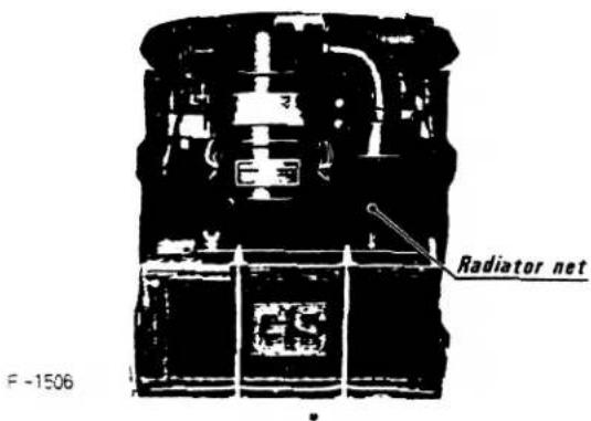
■ Cleaning the radiator net
The radiator is equipped with a net designed to prevent small particles of debris from entering the radiator coils. This screen must be cleaned whenever it becomes clogged with material. Clena this screen with water by directing the water through the rear of the radiator. If the screen clogs, engine overheating may result.
Antifreeze
Use only permanent type antifreeze of known quality. For solution mixture follow directions provided with the antifreeze. If you experience coolant loss due to evaporation, refill the system with water. If coolant loss is due to leaks, refill with antifreeze.
■ Repairing radiator leaks
To repair small leaks use Kubota radiator cement =40. To repair large leaks, see your Kubota dealer.
■ Radiator hoses (Water pipes)
Check to see that the radiator hoses are tightly connected every 150 hours of operation or every 6 months, whichever comes first.
(1) If a hose band comes loose, apply oil to the band screw and tighten it securely.
(2) The radiator hoses are made of rubber and can wear out whether the tractor is used or not. Replace them with new ones every two years. It is necessary to change hose bands at the same time.
| Name | Code No. | |
| M4500(DT) | M5500(DT) M7500(DT) | |
| Water pipe 1 | 15612-72851 | 15701-72851 |
| Band 1 | 15108-72873 | 15701-72872 |
| Water pipe | 15612-72941 | 15451-72941 |
| Band 2 | 15108-72873 | 15701-72962 |
(3) Should a radiator hose or a band become damaged or a hose dislocated before the two years are up, replace or repair as soon as possible. It would be extremely dangerous if the radiator hose came off during operation and hot water gushed out.
9. ELECTRICAL SYSTEM
■ Battery
The tractor is equipped with a single 12 volt battery.
If it becomes necessary to change the battery, use a battery of equal size and power.
BATTERY SPECIFICATIONS
| TYPE | Volts (V) | Number of plate per cell | Capacity | Volume of Electrolyte (Ω) | Normal Charging Rate (A) | ||
| at 20HR (Ah) | |||||||
| M4500 (DT) | G160 - 10 | 12 | 19 | 150 | 110 | 6.8 | 9 |
| M5500 (DT) M7500 (DT) | NX300-15 | 12 | 35 | 300 | 170 | 11.5 | 17 |
![[M4500(DT)] Battery](/content/2026/05/867607/images/9988e6431ce6b7df9f5505285423fa401396277e31998b3aa4a123a830e45ca7.jpg)
![[M5500(DT)] [M7500(DT)] Battery E-1616](/content/2026/05/867607/images/eae080ae3fe2ad32f85b5240f862385ab04b476dd485965843342e5a66eec7ce.jpg)
(1) "Jump Starting"
If it becomes necessary to connect a booster battery to the tractor battery to assist in starting the tractor in cold weather, or if the main battery is low, use the following procedure: connect the positive terminal on the booster battery to a ground point on the tractor. When grounding a booster battery do not ground the battery to thin metal or painted surfaces. Start the tractor following normal starting procedure.
(2) CLEANING THE BATTERY
Keep the battery case clean Wipe the battery case off with a damp cloth whenever necessary. To clean the battery terminals, use a solution of baking soda and water (¼ pound of baking soda to one quart of water). After washing the terminals with this solution, wash the battery and surrounding area with clean water. When cleaning the battery always check the battery cap vent holes to make sure they are clear.
(3) HANDLING THE BATTERY
Exercise caution when handling the battery. Don't tip the battery or electrolyte may spill on your clothing. Do not set the battery on cement. Do not drop, pound or in any way subject the battery case to undue stress. Do not expose the battery to heat at any time.
(4) BATTERY MAINTENANCE
Check the battery electrolyte level frequently. Keep the battery full at all times. Over time, the battery electrolyte may evaporate reducing the battery's capacity to hold a charge and provide power for tractor starting and electrical system operation. If the electrolyte level is low add distilled water to the battery until the battery is full. The battery is full when the electrolyte is 3/8th of an inch above the plates. (See illustration below.)

Each cell must be full for the battery to operate properly. Be careful when handling electrolyte. Electrolyte will eat holes in clothing, and when spilled on painted surfaces will remove paint and promote corrosion.
[NOTE]
A fully charged battery is protected from freezing down to -75^ while a discharged battery will freeze at 18^ .
Battery electrolyte level
![KUBOTA M5500 - [NOTE] - 1](/content/2026/05/867607/images/ca061fb9c0ad01300664fc646e8da456ec14645b8364c174a185e52af5c700bd.jpg)
Deficient
![KUBOTA M5500 - [NOTE] - 2](/content/2026/05/867607/images/5ccbcbf3c23688eaf0aa223b822b9fd3c792ecd82bde5eac63e37d049f839ce8.jpg)
Correct
![KUBOTA M5500 - [NOTE] - 3](/content/2026/05/867607/images/e35b09bb2b094232d5b1812671da5b7575ec55e909df9ff3c4c269674fa52847.jpg)
Excessive
Keep the battery clean by wiping the top and sides of the battery case with a damp cloth. Do not allow corrosion to build up on battery terminals. To prevent corrosion build-up apply a solution of 14 lb. of baking soda to 1 quart of water to the terminals. Be sure the battery caps are tight to prevent the solution from entering the cells.
After cleaning the battery, applying anti-corrosion solution to the terminals, or filling the battery, tighten all the caps and thoroughly flush the area around the battery with clean water.
![KUBOTA M5500 - [NOTE] - 4](/content/2026/05/867607/images/98b041165a1f3cda70735e8a3177d3186f17b51efc92bc6554879d74d8ff2578.jpg)
[NOTE]
Since water and electrolyte do not mix immediately, do not add water to the battery in freezing weather unless the tractor is to be run for 2 to 3 hours to allow complete mixing of the water and electrolyte.
(5) CHECKING SPECIFIC GRAVITY
To check specific gravity, use a battery hydrometer. A fully charged battery has a specific gravity reading of 1.260. The battery must be charged if the hydrometer reading is below 1.215.
The hydrometer reading must be corrected for temperature. Add four gravity points (0.004) for every ten degrees of electrolyte temperature above 80 degrees F. Subtract four gravity points for every ten degrees below 80^ F.
(6) COLD WEATHER BATTERY OPERATION
Your tractor battery may freeze in cold weather conditions if it is not kept full of electrolyte and fully charged. Cold weather has little effect on a fully-charged battery. Additionally, extra starting cranking power is needed when starting a cold engine in extremely cold weather conditions. To insure there is sufficient battery cranking power to start the engine, the battery must be full of electrolyte, fully charged and the terminals must be clean and making good contact with the battery cables.
(7) BATTERY REMOVAL AND INSTALLATION
To remove the battery, first disconnect the ground cable. Then disconnect the positive battery cable. Remove the battery hold-down clamp and lift the battery out.
Before installing the battery make sure both terminals are clean and there are no cracks in the battery case. Connect the positive cable first and tighten the clamp securely. Connect the negative terminal and secure the battery hold-down clamp. If any acid has been spilled, wash the battery and surrounding area thoroughly with clean water. Coat the terminals with the baking soda and water solution.

[CAUTION]
Kubota batteries are negative grounded only. Do not use a positive grounded battery in the tractor. Do not attempt to connect the positive cable to the negative pole on the battery. Reverse polarity can cause serious damage to the entire tractor electrical system. Connecting the negative terminal last will avoid the accidental occurrence of sparks which can cause battery explosion and burns.
(8) BATTERY STORAGE
If the tractor is to be stored for extensive periods of time (30 days or longer) remove the battery, fill the battery with electrolyte and charge the battery to a full charge. A battery is fully charged when the cells are all gassing freely (bubbles appear in each cell) and the specific gravity ceases to rise for three consecutive readings taken at hour intervals. Check and charge the battery every thirty days while in storage. Store the battery in a cool dry place but protect from freezing.
CHARGING TIMES FOR BATTERIES IN STORAGE
| Period of storage from manufactured (months) | Recharging (times) |
| 0-6 | about 5 hours |
| 6-12 | 10 |
| over 12 | 30 |
(9) BATTERY CHARGING PROCEDURES
To charge the battery, remove all battery caps and check electrolyte level. Fill if necessary. Connect the battery to the charger, connect the positive cable first, then the negative cable. Charge the battery until fully recharged. A slow trickle charge is better than a quick charge.
SPECIFIC GRAVITY CHART
| AIR TEMPERATURES | ||
| TEMPERATURE Ordinarily below 68°F (20°C) | TROPICAL Frequently above 68°F (20°C) | |
| sp. gr. of Electrolyte for Filling | 1.260 | 1.240 |
| sp. gr. of Electrolyte when fully charged | 1.260 to 1.275 | 1.240 to 1.255 |
■ Alternator and voltage regulator
The alternator is located on the left-hand side of the engine and is powered by a belt turned by a pulley running off the front of the crankshaft. The alternator provides electrical current for charging the battery and for other electrical requirements of the tractor.
The voltage regulator is located on the firewall between the engine and fuel tank. The voltage regulator acts to control the voltage output of the alternator.
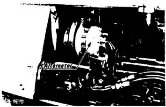
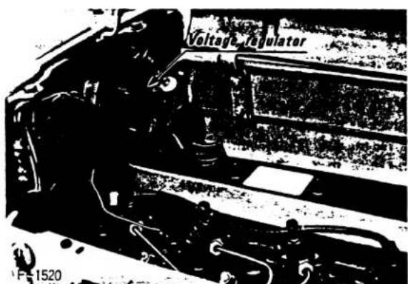
■ Alternator and voltage regulator servicing procedures
There are no service requirements for either the alternator or regulator; however, there are several precautions that should be observed while working on the electrical system.

● Always disconnect the batteries when working with or near the alternator or regulator.
- Be sure, in the event the voltage regulator or alternator wires are disconnected, that they be reconnected before connecting the battery cable back on the battery.
- Do not attempt to polarize an alternator.
- Do not ground alternator field circuit between the alternator and the regulator when the key is in the "ON" position or the engine is running.
- Do not ground the alternator output terminal or the circuit between the alternator and the battery.
- Do not operate the alternator on an open circuit; i.e. with the batteries disconnected or a broken wire between the battery and alternator.
■ Starter
The starter is located on the right-hand side of the engine. Under normal operating conditions the stater requires no maintenance. If the starter malfunctions, consult the trouble-shooting section of this manual or your KUBOTA Dealer.
In order that the starter operate properly, the battery must be fully charged. A malfunctioning starter can often be traced to a weak battery. If the starter will not turn the engine over, if there is a continuous clicking sound when the starter is engaged, check the battery charge before attempting to make repairs on the starter.
The starter is designed to operate under heavy loads for short periods of time. It is not advisable to operate the starter for more than 30 seconds of continuous operation. If, after several attempts, the engine will not start after 30 seconds of continuous starter engagement, consult the trouble-shooting section of this manual or your Kubota Dealer.
■ Fuses
The tractor electrical system is protected from potential damage by fuses. There are a total of seven fuses in the tractor electrical system. Six of the fuses are located in a fuse box on the firewall. The seventh fuse is an in-line fuse. Refer to the illustrations and chart below for the location of the fuses and fuse amperage.
Inoperative electrical components may indicate that a fuse has been blown. A blown fuse indicates that there is an overload or short somewhere in the electrical system.
Before replacing a blown fuse, determine why the fuse blew and make any necessary repairs. Failure to follow this procedure may result in serious damage to the tractor electrical system. Refer to the trouble-shooting section of this manual or your Kubota dealer for specific information dealing with electrical problems.
![[M4500(DT)] ①②③④⑤⑥ ⑦](/content/2026/05/867607/images/e30aacef9e7a24c8b99e8b52d25b6c612b8b148349781d71da47fb6a2a1e7610.jpg)
![[M5500(DT)] [M7500(DT)]](/content/2026/05/867607/images/6a4b802b630e7649eeef554c6a46f26af219bf0a003cd8b69cdaa563b7a11d88.jpg)
1 Fuse 1 3amp. ( 3A) 5 Fuse 5 8amp. ( 8A)
2 Fuse 2 3amp. ( 3A) 6 Fuse 6 8amp. ( 8A)
3 Fuse 3 20amp. (20A) 7 Fuse 7 60amp. (60A)
4 Fuse 4 8amp. ( 8A)
■ Protected circuits
(1) Fuse 1 .... Clearance lamps (optional)
(2) Fuse 2..... Fuel gauge, water thermometer, oil pressure pilot lamp, alternator warning lamp and PTO pilot lamp.
(3) Fuse 3 ...... Front and rear flasher,s flasher pilot lamps, radio and work lamp (Optional).
(4) Fuse 4 ..... Horn
(5) Fuse 5.....Head lamps (high beam), and illumination for control panel.
(6) Fuse 6 ..... Head lamps (lower beam)
(7) Fuse 7 ...... Check circuit against wrong battery connection.
10. FAN BELT ADJUSTMENT
Check the adjustment of the fan belt every time the engine oil is changed. When correctly adjusted the fan belt should have between 0.28 and 0.34 inches (7 to 9mm) of deflection in the middle of the longest span of the belt.
To adjust the fan belt tension, loosen the alternator mounting bolts and, using a lever placed between the alternator and the engine block, pull the alternator out until the deflection on the longest span of the belt falls within acceptable limits.
To replace the fan belt, loosen the alternator mounting bolts and move the alternator toward the engine block until the fan belt can be removed from the alternator pulley. With the belt removed from the alternator pulley, remove the belt from the crankshaft pulley and then slide the belt over the fan. It may be necessary to rotate the fan slightly to move the fan belt past the radiator fan shroud. To install a new belt, reverse this procedure.
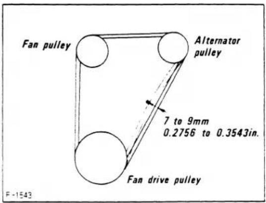
- PERIODIC SERVICE SCHEDULE
| Check every: | Service | Remarks |
| 50 hours | Grease the brake pedal shaft (3 spots) | |
| Grease the steering lever shaft (1 spot) | ||
| Grease the hydraulic power unit coupler section and the right lift rod (4 spots) | ||
| Grease the front wheel steering knuckle (2 spots)[Standard-types] | ||
| Grease the front axle support pipe (1 spot) [Standard-types] | ||
| Drain water in the fuel filter [M7500(DT)] | ||
| 150 hours | Check the clutch pedal free-play | Free-play should be between 1.2-1.6 in. (3-4cm) |
| Check the brake pedal free-play | Free-play should be between 1.4 - 1.8 in. (3.5 - 4.5cm)[M4500 (DT)]1.6 - 2.0 in. (4 - 5cm)[M5500 (DT) · M7500 (DT)] | |
| Check the PTO clutch control lever free-play | Free-play should be between 1.6-2.0 in. (4-5cm) | |
| Check the battery electrolyte level | ||
| Change engine oil [M4500 (DT)] | Engine oil CD (DS) : 13.4 qts. (12.7l) | |
| Replace oil filter (2) elements [M4500 (DT)] | ||
| Check the Toe-in | ||
| Check to see if the radiator hose band are slack | ||
| 200 hours | Change engine oil [M5500(DT)·M7500(DT)] | Engine oil CD (DS)M5500 (DT) : 10.4 qts. (9.8l)M7500 (DT) : 12.5 qts. (11.8l) |
| Grease the clutch release bearing (1 spot) | ||
| Clean the fuel pump [M5500 (DT) · M7500 (DT)] | ||
| Check the fan belt tension. Adjust as necessary | ||
| Clean hydraulic oil strainer and magnetic filter | ||
| 400 hours | Replace fuel filter (1) elements [M5500 (DT) · M7500 (DT)] | |
| Check the steering box oil level | ||
| Replace oil filter cartridges [M5500 (DT) · M7500 (DT)] | ||
| Replace fuel filter cartridges [M4500 (DT)] | ||
| Change power steering oil | ||
| Grease the front wheel hub bearings [Standard-types] | ||
| 600 hours | Change transmission oil for hydraulic unit | SAE 80 wt. gear oil 47.6 qts. (45l) |
| Change oil in the right and left front axle cases [DT-types] | SAE 80 wt. gear oil 3.7 qts. (3.5l) | |
| Change oil in the front differential gear case [DT-types] | SAE 80 wt. gear oil 3.7 qts. (3.5l) | |
| Change oil in the right and left front bevel gear cases[DT-types] | SAE 80 wt. gear oil 0.8 qt. (0.8l) | |
| 800 hours | Remove sediment in the fuel tank | |
| Replace fuel filter (2) element [M7500(DT)] | ||
| Clean the cooling system | Flush with commercial radiator cleaner and clear water | |
| Check the valve clearance [M5500 (DT) · M7500 (DT)] | Ask your Kubota dealer to check it | |
| Check the fuel injection pressure of the nozzle[M5500 (DT) · M7500 (DT)] |
- BATTERY TROUBLE SHOOTING
| Trouble | Cause | Corrective Measure | Preventive Measure |
| Starter will not engage. | Light have been left on. | Recharge the battery with battery charger. | Charge battery.Keep battery fully charged. |
| Battery has not been charged. | |||
| Poor battery terminal connection. | Clean the battery terminals and tighten cable clamps. | Keep terminals clean and cable clamps tight. Apply anticorrosives to terminals. | |
| Battery is dead. | Replace the battery. | ||
| Starter will not engage.Battery has been charged. | Insufficient charging. | Recharge the battery with slow trickle charge. | Give battery full charge before operating tractor. |
| Battery cell plates appear white in color. | Battery electrolyte level low. | Add distilled water and charge the battery. | Make frequent checks of battery electrolyte level. |
| Battery discharged. | Recharge the battery. | Keep battery fully charged. | |
| Battery will not take charge. | Battery is dead. | Replace the battery. | |
| Terminals are corroded and heat up. | Poor battery terminal connection. | Clean the terminals and tighten the cable clamps. | Keep terminals clean and cable clamps tight. |
| Battery electrolyte level drops rapidly after filling. | Crack or small hole in battery case. | Replace battery. | Tighten battery hold down clamp. |
13. ENGINE TROUBLE SHOOTING
| Trouble | Cause | Corrective Measures |
| Engine is difficult to start. | Blockage in fuel system. | (1) Check the fuel tank.Clean out trapped sediment.(2) Blocked fuel filter. Replace the fuel filter. |
| Air and water in fuel system. | (1) Check tightness of fuel line fittings.(2) Bleed the fuel system to remove trapped air. | |
| Crankcase oil to heavy for prevailing temperature conditions. | (1) Pour hot water over radiator.(2) See lubrication section of this manual for correct oil for use in temperature range in which tractor will be operated. | |
| Battery lacks the power to turn engine over. | (1) Charge the battery.(2) Use engine decompression device.(3) During winter months and other times of intermittent use remove the battery from the tractor, charge and store indoors. Reinstall the battery in the tractor only when the tractor is to be used. | |
| Engine lacks power. | Blockage in fuel system. | (1) Check the fuel system - Remove trapped sediment, air or water. |
| Air cleaner clogged. | (1) Clean air filter element. | |
| Engine stops suddenly. | Fuel tank low on fuel. | (1) Refuel - Bleed fuel system if fuel tank has been emptied. |
| Blockage in fuel system. | (1) Check the fuel system - Remove trapped sediment air or water. | |
| Exhaust smoke wrong color. | Poor quality fuel. | (1) Change to higher quality fuel. |

STORAGE
1. TRACTOR STORAGE
If you intend to store your tractor for an extended period of time, follow the procedures outlined below. These procedures will insure that the tractor is ready to operate with minimum preparation or refurbishing when it is removed from storage.
(1) Store the tractor indoor in a dry area that is protected from sunlight and excessive heat. If the tractor must be stored outdoors, cover it with a waterproof tarp.
(2) Change the engine crankcase oil and oil filter. Used crankcase oil will not protect internal engine parts from rust.
(3) Drain and flush the cooling system. Refill the system with a solution of water and anti-freeze.
(4) Clean the engine air filter.
(5) Run the engine to circulate oil and coolant throughout the engine block and internal moving parts.
(6) Fill the fuel tank with fuel.
(7) Close fuel tank petcock.
(8) Remove the battery from the tractor. Store the battery following the battery storage procedures outlined in the maintenance section of this manual.
(9) Seal the following with heavy gauge plastic and adhesive tape: The air cleaner inlet, exhaust outlet, radiator overflow tube and engine breather cap.
(10) With all implements lowered to the ground, coat any exposed hydraulic cylinder piston rods with grease.
(11) Paint exposed metal surfaces to protect them from corrosion.

(12) Jack the tractor up and place blocks under the front and rear axle so that all four tires are off the ground. Keep the tires out of direct sunlight and extreme heat.
(13) Hold the clutch pedal in the disengaged position by placing a block between the clutch pedal lever and the step plate.
2. REMOVING THE TRACTOR FROM STORAGE
(1) Check the tire air pressure and inflate the tires if they are low.
(2) Jack the tractor up and remove the support blocks from under the front and rear axle.
(3) Remove the protective plastic and coverings from the aire cleaner, exhaust pipe, radiator overflow tube and engine breather cap.
(4) Install the battery. Before installing the battery, be sure it is fully charged.
(5) Check the fan belt tension.
(6) Check all fluid levels (engine oil, transmission/hydraulic oil, engine coolant and any attached implements.)
(7) Open the fuel petcock.
(8) Remove the block between the clutch pedal shaft and the step plate.
(9) Start the engine. Observe all gauges. If all gauges are functioning properly and reading normal, move the tractor outside. Once outside, park the tractor and let the engine run at an idle for at least five minutes. While the engine is warming up, walk around the tractor and make a visual inspection looking for evidence of oil or water leaks.
(10) With the engine fully warmed up, release the parking brake and test the brakes for proper adjustment as you move forward. Adjust the brakes as necessary.
SPECIFICATIONS
- SPECIFICATIONS 43
-
TRACTOR SPEED 45
-
SPECIFICATIONS
| Model | M4500 | M4500DT | |||
| Engine | Model | S2600-A | |||
| Type | Vertical, water-cooled, 4-cycle diesel engine | ||||
| Number of cylinders | 6 | ||||
| Total displacement | 158.5 Cu.in. (2598cm3) | ||||
| Bore and stroke | 3-15/64 x 3-15/64 in. (82 x 82mm) | ||||
| Maximum output | Bare 55.5 HP (41.4 kW)/2600 rpm (43.3 r/s) | ||||
| Maximum output (PTO) | *49 HP (36.55 kW) | ||||
| Maximum torque | 117.6 ft.lbs. (16.2 kgf·m; 158 N·m)/1400 rpm (23.3 r/s) | ||||
| Battery capacity | G160-10 [Dry, 12V 150AH (110Ah-20HR)] | ||||
| Fuel | No. 2 diesel fuel | ||||
| Fuel tank capacity | 14.3 Gallons (54l) | ||||
| Engine oil tank capacity | 13.42 Quarts (12.7l) | ||||
| Cooling system capacity | 8.9 Quarts (8.4l) | ||||
| Dimensions | Overall length | 132-1/2 in. (3365mm) | 137-5/8 in. (3495mm) | ||
| Overall width | 66-3/8 in. (1685mm) | 70-1/4 in. (1785mm) | |||
| Overall height | 89 in. (2260mm) | 90-1/8 in. (2290mm) | |||
| Wheel base | 78-1/8 in. (1985mm) | 79-1/2 in. (2020mm) | |||
| Tread | Front | 50-3/8~78 in.(1280~1980mm) | 55-7/8 in. (1420mm) | ||
| Rear | 51-3/16 ~ 74-13/16 in.(1300 ~ 1900mm) | ||||
| Minimum ground clearance | 15-1/2 in. (395mm) | 12-3/8 in. (315mm) | |||
| Weight | 4232.8 lbs. (1920kg) | 4850 lbs. (2200kg) | |||
| Travelling system | Tire size | Front tires | 6.00-16-6PR (AG) | 8.3/8-24-6PR (AG) | |
| Rear tires | 14.9/13-28-6PR(AG) | ||||
| Clutch | Single dry plate, double type | ||||
| Steering | Ball screw | ||||
| Braking system | Single system, independent, wet type disc brake | ||||
| Differential system | Bevel gears (differential lock) | ||||
| Hydraulic unit | Hydraulic control system | Position control, draft control and mixed control | |||
| Pump-up capacity | 7.3 Gallons/min. (27.5 l/min) | ||||
| Three-point hitch | Category 1 & 2 | ||||
| Maximum lifting force | 3300 lbs. (1500 kg) | ||||
| Traction system | Swing drawbar adjusts height and direction | ||||
| PTO shaft | Live PTO | Direction of turning | Clockwise, viewed from tractor rear | ||
| Standard PTO | 540 rpm (9 r/s)/2193 rpm (36.6 r/s) for engine | ||||
| Ground PTO | Direction of turning | Clockwise, viewed from tractor rear | |||
| PTO speed | 1.59 turns/m (with 14.9-28 tires) | ||||
| M5500 | M5500DT | M7500 | M7500DT | ||
| D3000-A | V4000-A | ||||
| Vertical, water-cooled, 4-cycle diesel engine | Vertical, water-cooled, 4-cycle diesel engine | ||||
| 3 | 4 | ||||
| 182.2 Cu. in. (2987 cc) | 243 Cu. in. (3983 cc) | ||||
| 4-9/64 x 4-17/32 in. (105 x 115mm) | 4-9/64 x 4-17/32 in. (105 x 115mm) | ||||
| Bare 63 HP (47 kW)/2400 rpm | Bare 81 HP (60.4 kW)/2400 rpm | ||||
| *53.9 HP (40.2 kW) | *72 HP (53.71 kW) | ||||
| 150.3 ft. lbs. (20.8 kgf·m; 204 N·m)/1400 rpm | 201.7 ft. lbs. (27.9 kgf·m; 273 N·m)/1400 rpm | ||||
| NX300-15 (Dry; 12V 300AH) | NX300-15 (Dry; 12V 300 AH) | ||||
| No. 2 diesel fuel | No. 2 diesel fuel | ||||
| 14.3 Gallons (54l) | 14.3 Gallons (54l) | ||||
| 10.4 Quarts (9.8l) | 12.5 Quarts (11.8l) | ||||
| 12.3 Quarts (11.6l) | 13.8 Quarts (13l) | ||||
| 132-5/8 in. (3370mm) | 139 in. (3530mm) | 142-7/8 in. (3630mm) | 147-7/8 in. (3755mm) | ||
| 66-3/8 in. (1685mm) | 70-5/8 in. (1795mm) | 71-1/4 in. (1810mm) | 72 in. (1830mm) | ||
| 87-3/16 in. (2215mm) | 88-3/4 in. (2255mm) | 89-1/8 in. (2265mm) | 89-1/8 in. (2265mm) | ||
| 79-7/8 in. (2030mm) | 80-7/8 in. (2055mm) | 84-7/8 in. (2155mm) | 85-5/8 in. (2175mm) | ||
| 50-3/8~78 in.(1280~1980mm) | 55-7/8 in. (1420mm) | 53-7/8 ~ 77-1/2 in.(1370 ~ 1970mm) | 57-7/8 in. (1470mm) | ||
| 51-3/16 ~ 74-13/16 in.(1300 ~ 1900mm) | 55-1/8 ~ 74-13/16 in.(1400 ~ 1900mm) | ||||
| 15 in. (380mm) | 12-3/8 in. (315mm)(at the bottom of front axle) | 18-1/4 in. (465mm) | 13-3/8 in. (340mm)(at the bottom of front axle) | ||
| 4629.7 lbs. (2100kg) | 5114.7 lbs. (2320kg) | 4916 lbs. (2230kg) | 5666 lbs. (2570kg) | ||
| 6.00-16-6PR (AG) | 8.3/8-24-6PR (AG) | 7.50-16-6PR | 9.5/9-24-6PR (AG) | ||
| 14.9/13-28-6PR (AG) | 16.9/14-30-6PR (AG) | ||||
| Single dry plate, double type | Single dry plate, double type | ||||
| Ball screw | Ball screw | ||||
| Single system, independent, wet type disc brake | Single system, independent, wet type disc brake | ||||
| Bevel gears (differential lock) | Bevel gears (differential lock) | ||||
| Position control, draft control and mixed control | Position control, draft control and mixed control | ||||
| 8.06 Gallons/min. (30.5l/min.) | 8.06 Gallons/min. (30.5l/min.) | ||||
| Category 1 & 2 | Category 1 & 2 | ||||
| 3300 lbs. (1500 kg) (at the end of bottom links) | 3300 lbs. (1500 kg) (at the end of bottom links) | ||||
| Swinging drawbar adjusts height and direction | Swinging drawbar adjusts height and direction | ||||
| Clockwise, viewed from tractor rear | Clockwise, viewed from tractor rear | ||||
| 540 rpm (2016 rpm for engine) | 540 rpm (2016 rpm for engine) | ||||
| Clockwise, viewed from tractor rear | Clockwise, viewed from tractor rear | ||||
| 1.55 turns/m (with 14.9 - 28 tires) | 1.51 turns/m (with 16.9 - 30 tires) | ||||
*Maximum P.T.O. horse power in Official Test.
- TRACTOR SPEED
| MODEL | M4500 (DT) | M5500 (DT) | M7500 (DT) | |||||
| At rear tires | 14.9/13-28 | 14.9/13-28 | 16.9/14-30 | |||||
| Creeper lever | H-L lever | Main lever | Speed | Speed | Speed | |||
| mph | km/h | mph | km/h | mph | km/h | |||
| LDo not two when using creep gears | L | 1 | 0.26 | 0.42 | 0.27 | 0.43 | 0.28 | 0.45 |
| 2 | 0.32 | 0.51 | 0.33 | 0.52 | 0.34 | 0.55 | ||
| 3 | 0.53 | 0.86 | 0.55 | 0.88 | 0.58 | 0.92 | ||
| 4 | 0.73 | 1.17 | 0.76 | 1.21 | 0.78 | 1.25 | ||
| R | 0.34 | 0.55 | 0.36 | 0.57 | 0.37 | 0.59 | ||
| H | 1 | 0.97 | 1.56 | 1.00 | 1.61 | 1.05 | 1.68 | |
| 2 | 1.18 | 1.90 | 1.23 | 1.96 | 1.28 | 2.04 | ||
| 3 | 1.99 | 3.20 | 2.06 | 3.30 | 2.14 | 3.43 | ||
| 4 | 2.72 | 4.37 | 2.72 | 4.35 | 2.93 | 4.69 | ||
| R | 1.27 | 2.05 | 1.33 | 2.12 | 1.38 | 2.20 | ||
| H | L | 1 | 1.50 | 2.43 | 1.56 | 2.5 | 1.63 | 2.6 |
| 2 | 1.84 | 2.96 | 1.94 | 3.1 | 2.00 | 3.2 | ||
| 3 | 3.09 | 4.97 | 3.19 | 5.1 | 3.31 | 5.3 | ||
| 4 | 4.23 | 6.80 | 4.38 | 7.0 | 4.56 | 7.3 | ||
| R | 1.98 | 3.19 | 2.06 | 3.3 | 2.13 | 3.4 | ||
| H | 1 | 5.64 | 9.08 | 5.88 | 9.4 | 6.06 | 9.7 | |
| 2 | 6.87 | 11.05 | 7.13 | 11.4 | 7.44 | 11.9 | ||
| 3 | 11.56 | 18.61 | 12.00 | 19.2 | 12.5 | 20.0 | ||
| 4 | 15.80 | 25.42 | 16.40 | 26.2 | 17.1 | 27.3 | ||
| R | 7.42 | 11.94 | 7.68 | 12.3 | 8.00 | 12.8 | ||
WIRING DIAGRAM
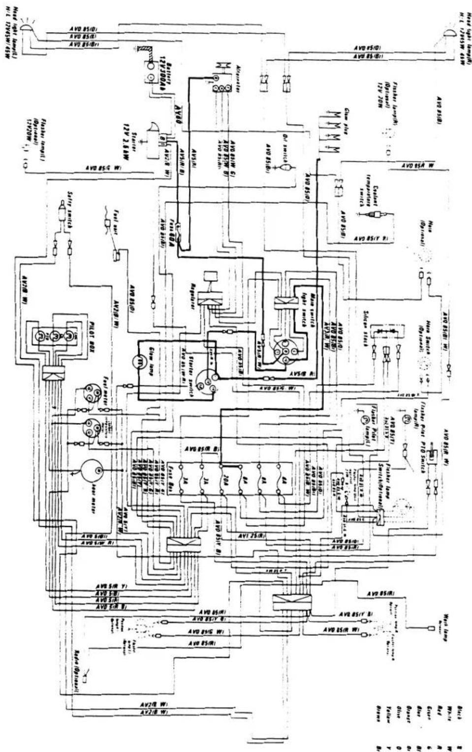
flowchart
graph TD
    A["Power Supply"] --> B["Switch 1"]
    A --> C["Switch 2"]
    A --> D["Switch 3"]
    A --> E["Switch 4"]
    A --> F["Switch 5"]
    A --> G["Switch 6"]
    A --> H["Switch 7"]
    A --> I["Switch 8"]
    A --> J["Switch 9"]
    A --> K["Switch 10"]
    A --> L["Switch 11"]
    A --> M["Switch 12"]
    A --> N["Switch 13"]
    A --> O["Switch 14"]
    A --> P["Switch 15"]
    A --> Q["Switch 16"]
    A --> R["Switch 17"]
    A --> S["Switch 18"]
    A --> T["Switch 19"]
    A --> U["Switch 20"]
    A --> V["Switch 21"]
    A --> W["Switch 22"]
    A --> X["Switch 23"]
    A --> Y["Switch 24"]
    A --> Z["Switch 25"]
    A --> AA["Switch 26"]
    A --> AB["Switch 27"]
    A --> AC["Switch 28"]
    A --> AD["Switch 29"]
    A --> AE["Switch 30"]
    A --> AF["Switch 31"]
    A --> AG["Switch 32"]
    A --> AH["Switch 33"]
    A --> AI["Switch 34"]
    A --> AJ["Switch 35"]
    A --> AK["Switch 36"]
    A --> AL["Switch 37"]
    A --> AM["Switch 38"]
    A --> AN["Switch 39"]
    A --> AO["Switch 40"]
    A --> AP["Switch 41"]
    A --> AQ["Switch 42"]
    A --> AR["Switch 43"]
    A --> AS["Switch 44"]
    A --> AT["Switch 45"]
    A --> AU["Switch 46"]
    A --> AV["Switch 47"]
    A --> AW["Switch 48"]
    A --> AX["Switch 49"]
    A --> AY["Switch 50"]
    A --> AZ["Switch 51"]
    A --> BA["Switch 52"]
    A --> BB["Switch 53"]
    A --> BC["Switch 54"]
    A --> BD["Switch 55"]
    A --> BE["Switch 56"]
    A --> BF["Switch 57"]
    A --> BG["Switch 58"]
    A --> BH["Switch 59"]
    A --> BI["Switch 60"]
    A --> BJ["Switch 61"]
    A --> BK["Switch 62"]
    A --> BL["Switch 63"]
    A --> BM["Switch 64"]
    A --> BN["Switch 65"]
    A --> BO["Switch 66"]
    A --> BP["Switch 67"]
    A --> BQ["Switch 68"]
    A --> BR["Switch 69"]
    A --> BS["Switch 70"]
    A --> BT["Switch 71"]
    A --> BU["Switch 72"]
    A --> BV["Switch 73"]
    A --> BW["Switch 74"]
    A --> BX["Switch 75"]
    A --> BY["Switch 76"]
    A --> BZ["Switch 77"]
    A --> CA["Switch 78"]
    A --> CB["Switch 79"]
    A --> CC["Switch 80"]
    A --> CD["Switch 81"]
    A --> CE["Switch 82"]
    A --> CF["Switch 83"]
    A --> CG["Switch 84"]
    A --> CH["Switch 85"]
    A --> CI["Switch 86"]
    A --> CJ["Switch 87"]
    A --> CK["Switch 88"]
    A --> CL["Switch 89"]
    A --> CM["Switch 90"]
    A --> CN["Switch 91"]
    A --> CO["Switch 92"]
    A --> CP["Switch 93"]
    A --> CQ["Switch 94"]
    A --> CR["Switch 95"]
    A --> CS["Switch 96"]
    A --> CT["Switch 97"]
    A --> CU["Switch 98"]
    A --> CV["Switch 99"]
    A --> CW["Switch 100"]

    subgraph Power Supply
        D
        E
        F
        G
        H
        I
        J
        K
        L
        M
        N
        O
        P
        Q
        R
        S
        T
        U
        V
        W
        X
        Y
        Z
        AA
        AB
        AC
        AD
        AE
        AF
        AG
        AH
        AI
        AJ
        AK
        AL
        AM
        AN
        AO
        AP
        AQ
        AR
        AS
        AT
        AU
        AV
        AW
        AX
        AZ
        BA
        BB
        BC
        BD
        BE
        BF
        BG
        BH
        BI
        BJ
        BK
        BL
        BM
        BN
        BO
        BP
        BQ
        BR
        CA
        CB
        CC
        CD
        DE
        EF
        GF
        GH
        IG
        AH
        AI
        AJ
        AK
        AL
        AM
        AN
        AO
        AP
        AQ
        AR
        AS
        AT
        AU
        AV
        AW
        AX
        AZ
        BA
        BB
        BC
        BD
        BE
        BF
        BG
        BH
        BI
        AJ
        AK
        AL
        AM
        AN
        AO
        AP
        AQ
        AW
        AX
        AZB
        BA
        BBB
        BC
        BD
        BEB
        BF
        BGB
        BH
        BIB
        AJB
        AKB
        BAIB
        BBIBB
        BCIBBIBBIBBIBBIBBIBBIBBIBBIBBIBBIBBIBBIBBIBBIBBIBBIBBIBBIBBIBBIBBIBBIBBIBBIBBIBBIBBIBBIBBIBBIBBIBBIBBIBBIBBIBBIBBIBBIBBIBBIBBIBBIBBIBBIBBIBBIBBIBBIBBIBBIBBBI

    %% Additional connections shown in the diagram; the diagram contains multiple labeled nodes (e.g., 'MOSA' or 'MOSBA') and labels (e.g., 'MOCA', 'SALI', 'AVG', 'AVG'. The diagram is designed to plot a single node on the circuit.