
F.01U.305.289 - Carte réseau/Adaptateur BOSCH - Gratis brugsanvisning og manual
Find enhedens vejledning gratis F.01U.305.289 BOSCH i PDF-format.

Brugerspørgsmål om F.01U.305.289 BOSCH
0 spørgsmål om dette apparat. Besvar dem du kender, eller stil dit eget.
Stil et nyt spørgsmål om dette apparat
Download vejledningen til din Carte réseau/Adaptateur i PDF-format gratis! Find din vejledning F.01U.305.289 - BOSCH og tag din elektroniske enhed tilbage i hånden. På denne side er alle dokumenter nødvendige for brugen af din enhed offentliggjort. F.01U.305.289 af mærket BOSCH.
BRUGSANVISNING F.01U.305.289 BOSCH
1
Important Safety Information
- The unit should be connected to PoE networks only, without routing to the outside plant.
- Only qualified personnel can install or remove the unit.
- The unit DATA IN and DATA & POWER OUT ports are shielded RJ45 data sockets. They cannot be used as Plain Old Telephone Service (POTS) telephone sockets. Only RJ45 data connectors can be connected to these sockets.
- The AC wall socket-outlet must be near the unit and easily accessible. You can remove AC power from the unit by disconnecting the AC power cord from either the wall socket-outlet or the unit appliance coupler.
-The unit DATA IN and DATA & POWER OUT interfaces are qualified as Safety Extra-Low Voltage (SELV) circuits according to IEC 60950-1. These interfaces can only be connected to SELV interfaces on other equipment. - The unit should only be connected to the IP device with which it was bought. Using the unit with other IP devices can cause damage to the IP device.
2
- Read the installation instructions before connecting the unit to its power source.
- Follow basic electricity safety measures whenever connecting the unit to its power source.
- A voltage mismatch can cause equipment damage and may pose a fire hazard. If the voltage indicated on the label is different from the power outlet voltage, do not connect the unit to this power outlet.
- The unit can be used only in Restricted Access Locations.
- Do not use a cross-over cable between the output and the camera.
- Do not to cover unit or block the airflow to the PoE with any foreign objects. Keep the unit away from excessive heat and humidity and free from vibration and dust.
- Ensure that the cable length from Ethernet network source to the terminal does not exceed 100 meters (330 feet). The PoE is not a repeater and does not amplify the Ethernet data signal.
- No On/Off switch exists; simply plug the unit into an AC power source.
3
Mounting instructions
- Install two screws in the wall or shelf
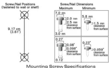
- Align the unit's mounting slots to capture the surface screws.
4
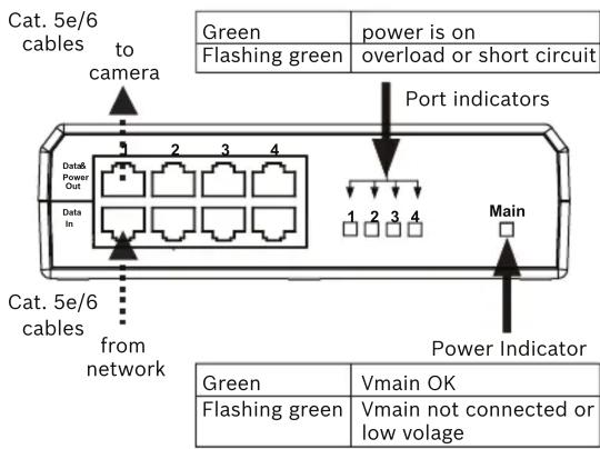
Connections
- Connect the unit to an AC outlet (100 - 240 VAC) using the supplied power cord.
- Connect the DATA IN (input) to the remote Ether-net network.
- Connect the DATA & POWER OUT (output) to the camera (do not use a cross-over cable between the output and the camera).
AC Power Cord Set:
- The power cord must have regulatory agency approval for the specific country in which it is used (for example UL, CSA, VDE, etc.).
- The power cord must be a three-conductor type (two current carrying conductors; one ground conductor) terminated on one end by an IEC 60320 appliance coupler (for connection to the unit), and on the other end by a plug containing a ground (earth) contact.
- The power cord must be rated for a minimum of 250 VAC RMS operation, with a minimum rated current capacity of 5 amps (or a minimum wire gauge of 18 AWG (0.75mm^2) .
- A unit installed in Australia requires power cords with a minimum wire gauge of 16 AWG (1.0 mm ^2 ).

Disposal - Your Bosch product was developed and manufactured with high-quality material and components that can be recycled and reused. This symbol means that electronic and electrical appliances, which have reached the end of their working life, must be collected and disposed of separately from household waste material. Separate collecting systems are usually in place for disused electronic and electrical products. Please dispose of these units at an environmentally compatible recycling facility, per European Directive 2012/19/EU.
EMC Compliance
- FCC Part 15 class B and EN55022 class B
- EN55024
- VCCI
Safety Compliance
- UL/cUL per 60950-1
- GS mark
More information
For more information please contact the nearest Bosch Security Systems location or visit:
http://www.boschsecurity.com/catalog_overview.htm
NPD-5004-POE
4-port Midspan PoE Injector

BOSCH
Quick Installation Guide
Bosch Security Systems B.V.
Torenallee 49
5617 BA Eindhoven
The Netherlands
www.boschsecurity.com
© Bosch Security Systems B.V., 2015

AM18-Q0697 | 2015-09 | v1.0
Mærke : BOSCH
Model : F.01U.305.289
Kategori : Carte réseau/Adaptateur