
NR-1019 - Modtager NIKKO - Gratis brugsanvisning og manual
Find enhedens vejledning gratis NR-1019 NIKKO i PDF-format.

Brugerspørgsmål om NR-1019 NIKKO
0 spørgsmål om dette apparat. Besvar dem du kender, eller stil dit eget.
Stil et nyt spørgsmål om dette apparat
Download vejledningen til din Modtager i PDF-format gratis! Find din vejledning NR-1019 - NIKKO og tag din elektroniske enhed tilbage i hånden. På denne side er alle dokumenter nødvendige for brugen af din enhed offentliggjort. NR-1019 af mærket NIKKO.
BRUGSANVISNING NR-1019 NIKKO
AM/FM T-LOCKED STEREO RECEIVER
NR-1019
OWNER'S MANUAL
NIKKO
Thank you very much for selecting the NIKKO model NR-1019 receiver. Every NIKKO product passes a series of severe tests before shipment to insure maximum reliability. To get the most out of your receiver, please read this manual carefully and follow its instructions fully. If there are any questions, please contact your nearest Nikko dealer or Nikko Audio.
Cautions 3
Functions of Operating parts....4,5
Stereo system arrangement....6
Connections and Operation
Speaker connection and use. 7
Turntable connection and record play....8
Connection and use of AUX input jacks. 8
Connection and use of Headphone 8
Tape Deck connection, recording and playback. 9
Connection of Antenna 9,10
AM reception....9
FM reception....10
Use of Accessory Functions....11
Specifications....12
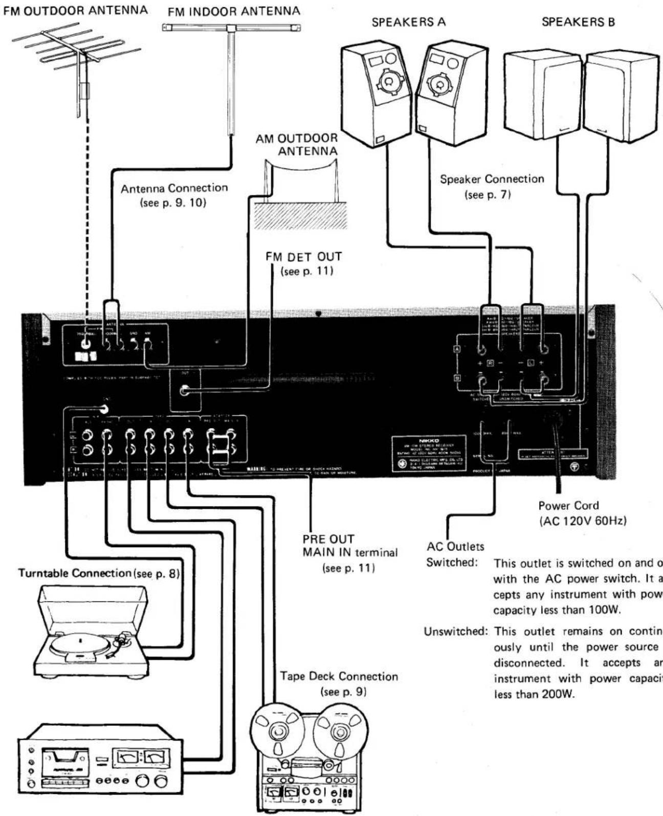
- Any pair of speakers rated at 4 to 16 ohms impedance can be connected to either the A or B Speaker Terminals. If 2 sets of speakers are to be played simultaneously, each speaker must have at least an impedance of 8 ohms to avoid any damage to the receiver.
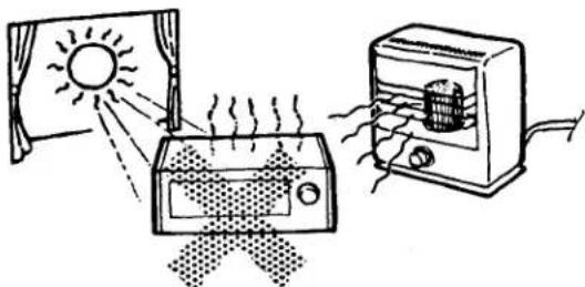
● Never attempt to connect more than one pair of speakers to one speaker terminal at any time. - Do not expose the receiver to direct sunlight or high temperatures. Avoid dust, excessive humidity, or moisture.
- To clean the cabinet, use a soft, dry cloth or silicon cloth. DO NOT USE ANY CHEMICAL SOLUTION SUCH AS BENZINE OR THINNER, AS IT AFFECTS THE FINISH ON THE CABINET.
- Place the receiver on a flat surface free from vibration. Maintain adequate ventilation. If trouble arises with the receiver, contact your nearest NIKKO Warranty Service Station immediately.
WARNING: To prevent fire or shock hazard, do not expose this appliance to rain or moisture.
- Ventilation holes are provided in top and bottom of the cabinet. Do not remove the feet (polyethylene) from the bottom plate or close the ventilation holes. Do not place the unit on a confined shelf, or put any instrument on top of the unit. Allow at least 5 inches clearance around the unit to ensure proper ventilation.
natural_image
Illustration of a solar heating system with a sun, heater, and heater emitting heat (no text or symbols)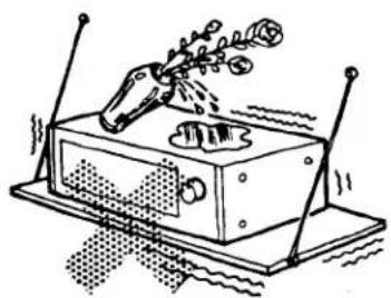
natural_image
Illustration of a mechanical device with a lever and base, emitting particles (no text or symbols)Operating Precautions
Howling, hum or other unpleasant sounds may occur while playing records or tapes. Some possible causes are given below.
(1) If the turntable is placed directly on or close to a speaker, a vibration of the sound from the speaker can be picked up by the cartridge, thus causing "howling". The turntable can be protected from a vibration by separating it from the speaker (approximately 8 to 10 ft.), so that no vibration can be transmitted. A thick cushion (such as a typewriter pad or sponge-type shock absorber) should be placed under the player cabinet for purposes of reducing such vibrations.
(2) When the turntable is connected with non-shielded cable or lead wire, "hum" may occur. The same situation also occurs when the outer mesh (ground wire) and the core wire (signal) are reversed, or the turntable motor is not properly grounded. This last example may occur even when shielded cable is used.
- Protector
This unit is designed and built with highly stable circuits and highly reliable component parts. However, if speaker cords are connected incorrectly with reversed polarity, or if connection becomes loose during sound reproduction, abnormally large low frequencies may be produced, thus damaging the speakers.
The protector is provided for preventing such trouble, and lighting up of this indicator means that such unusual state has occurred. Therefore, if the indicator illuminates during playback (reproduced sound from the speakers will stop simultaneously), check each cord for loose connection.
The protector is also provided for noise muting function: When the power switch is turned on, the protector indicator illuminates for several seconds until the circuit stabilizes, indicating that the speaker circuit is separated.
Name and purpose of controls on the front panel.
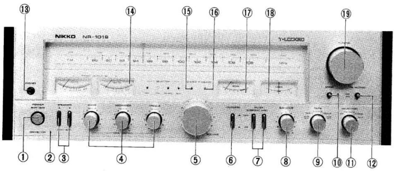
1. Power
This knob turns the power on and off.
2. Protector (see p. 3)
This indicator will illuminate if shortcircuit occurs in the speaker output circuit, or if any unusual state occurs in the unit. When the power switch is turned on, this indicator remains illuminated until operation of this unit stabilizes. The indicator will go out after approximately 5 \~ 7 seconds, and the reproduced sound will be heard from the speakers.
3. Speakers (see page 7.)
These speaker switches are used to select operation of the two sets of speakers. That is, the speaker set A, B, or A + B may be operated, or all speakers may be disconnected from the unit so that the headphones are used.
4. Tone Control (see P. 11)
BASS .....Controls the level of the low frequencies.
MIDRANGE...Controls the level of the middle frequencies.
TREBLE....Controls the level of the high frequencies.
5. Volume
This knob controls the volume level. Turn it clockwise to increase the volume and counterclockwise to decrease the volume. Be sure to turn the knob all the way to the left before switching on the power. Then raise the volume level gradually to the desired loudness.
Operate the Volume Control after the protector indicator has gone out.
6. Loudness (see p. 11)
When you listen at very low volume level, use this switch to restore the natural tonal balance.
7. Filter (see p. 11)
Subsonic: This switch cuts out noise in the low frequency range.
High: This switch cuts out noise in the high frequency range.
8. Balance (see p. 11)
The Balance control can be used to change the relative volume levels between left and right channels.
9. Tape (see p. 8)
This 5-position switch functions as follows:
DUB 1→2: For tape dubbing from tape deck connected to TAPE 1 to tape deck connected to TAPE 2.
TAPE 1: For tape playback from the tape deck connected to TAPE 1.
SOURCE: For playing AM, FM, PHONO and AUX.
TAPE 2: For tape playback from the tape deck connected to TAPE 2.
DUB 2→1: For tape dubbing from tape deck connected to TAPE 2 to tape deck connected to TAPE 1.
10. Mono
Press this switch for monophonic listening pleasure. (blended Left and Right signals.)
11. Selector
This 5-position switch functions as follows:
ÁM: For AM reception.
FM: For FM reception.
PHONO: For playing a turntable connected to the PHONO jacks.
AUX: For playing an external sound source connected to the AUX jacks.
12. FM Muting
Press this switch to eliminate of interstation noise during FM reception. Do not use the Muting Switch if the FM signal is weak.
13. Phones (see p. 8)
For connection of stereo headphone.
14. Power meter
The speaker output levels of left and right channels are indicated on the respective power meters.
You can control the output levels of source signal by using the VOLUME knob (5). The speaker output level is indicated in watts.
15. Stereo
This indicator illuminates during FM stereo reception.
16. T-Locked (see p. 11)
This indicator illuminates when accurate FM tuning is accomplished. After selecting the desired FM station, remove your hand so that the T-Locked is activated.
17. Signal Strength Meter (see p. 10, 11)
The signal strength meter is used to aid in obtaining the best radio reception. Maximum deflection of the needle to the right indicates the best AM or FM reception.
18. Center Tuning Meter (see p. 11)
This meter is used for FM tuning only. When a desired FM station is tuned properly, the meter will be in the center position.
19. Tuning Knob
This knob selects any desired AM or FM station.
Do not plug the power cord into an outlet until all connections are completed. Be sure to keep the power switch turned off.
SPEAKER CONNECTION AND USE
There are speaker terminals for two systems (A and B) in this unit. Two sets of speakers can be connected simultaneously. The speaker switch on the front panel allows the selection of System A, System B or both Systems A and B.
- Speaker Impedance
Any type of speaker having 4 to 16 ohms impedance may be used. However, when both A and B speaker systems are being used simultaneously, you should not use 4 ohm speakers with this equipment. The protection circuit will activate immediately and shut off all output power. Use 8 to 16 ohm speakers instead.
- Connector
To prevent the deterioration of the speaker connector damping factor, use the thickest power cables available.
(i.e. AC power cord-19AWG preferred)
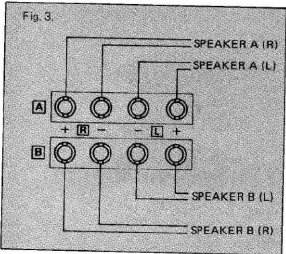
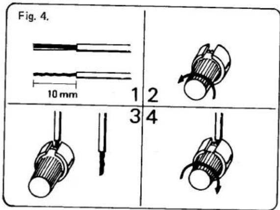
- Connection Method
Complete the connection to the speaker terminals in accordance with Fig. 3 and Fig. 4. (Left and Right channels (L, R) and polarity (+, -)).
- Speaker Location
In general, it is recommended to install a speaker with its back against a hard wall. This is because the back wall does not absorb the sound of low-frequencies and will have the effect of preventing the deterioration of bass characteristics.
If the opposite wall is of a hard surface, it may reflect, rather than absorb, these same bass characteristics. Therefore, if the opposite wall from the speaker is of a hard surface (i.e. Glass Door), it is recommended to provide a thick curtain or buffer of some kind to improve the acoustics in the listening area.
TURNTABLE CONNECTION AND RECORD PLAY
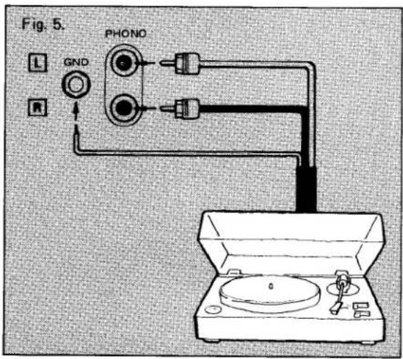
- Connection
Connect your record player to PHONO terminal of the unit, using pin-plug cords. If your record player has a ground lead, connect it to the ground terminal of the unit. The power cord of the record player may be connected to the AC outlet at the rear of the unit.
- Set the Selector Switch to the appropriate position according to the type of source used.
- Set the Tape Switch to SOURCE.
- Set the Volume Control to the desired position.
- If you wish to record while PHONO or AUX is in use, simply set your tape recorder to recording mode.
- Cartridge
Magnetic cartridge can be used with this unit using the PHONO input. Ceramic cartridge can be used by using the AUX input. The PHONO input sensitivity is 2.5mV with an allowable maximum input voltage of 200 mV. Moving coil cartridge require a headamp or a step-up transformer between the cartridge and the PHONO input.
CONNECTION AND USE OF AUX INPUT JACKS
For Playback only:
If a tuner, tape dack or cassette deck is to be used, connect its output jacks to the AUX jacks. These jacks have an input sensitivity of 150mV and an input impedance of 47K ohms, equal to the TAPE jacks.
Set the selector switch to AUX, the TAPE switch to SOURCE and adjust the volume.
CONNECTION AND USE OF HEADPHONES
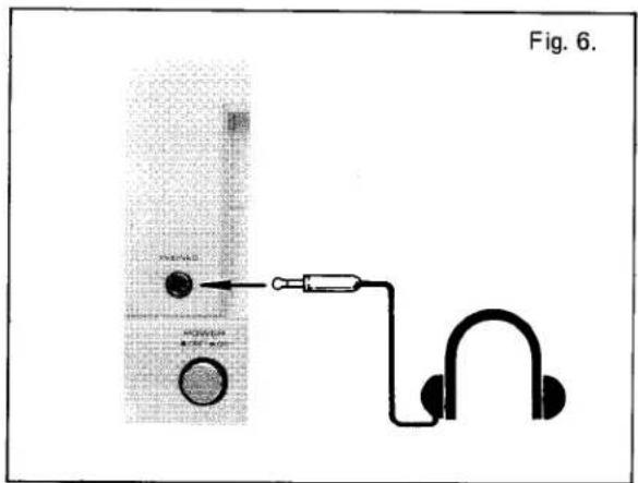
- Connection
Insert the headphone connection plug into the phone jack on the front panel.
- Use
The signal always comes through the Phone jack regardless of whether the speaker switch is set to the ON or OFF position. When listening through the headphones, turn the speaker switch to the OFF position.
TAPE DECK CONNECTION, RECORDING & PLAYBACK
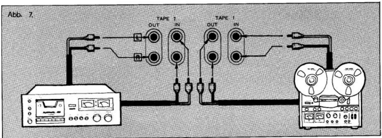
- Connection
There are recording and playback connection jacks for two separate tape decks on the rear panel. Connect the tape deck output (Line Out) jacks to the receiver TAPE IN jacks, and the tape deck input (Line In) jacks to the receiver TAPE OUT jacks. Be sure you do not confuse the left and right leads.
- Tape Playback
- Set the Tape switch to TAPE 1 or TAPE 2, depending upon which tape deck you want to use.
(The Selector switch setting has no effect in this case.)
- Begin tape play and turn up the receiver volume to the desired level.
- Tape Recording
When the dubbing switch is set to Source, the signal available for recording will be the one chosen by the Selector switch. In this case the volume and Tone control knobs will have no effect on the recorded signal.
- Once the Selector switch is set to the signal you wish to record, final adjustment of recording conditions should be made with the tape deck controls.
- Use the tape deck control to set the recording level.
- Monitoring the Recordings
If your tape deck is a three-head type, you can use the Tape switch to check the recording conditions. Set to Source for listening to the signal before it is recorded, then to TAPE 1 or TAPE 2 (depending upon which set of terminals are being used) to listen to the just-recorded signal.
- Tape Dubbing
When two tape decks are connected to this receiver dubbing can be performed in either direction. To copy from deck TAPE 1 to deck TAPE 2, set the Tape switch to "Dub 1 → 2." To dub in the other direction, set to "Dub 2 → 1."
CONNECTION OF ANTENNA
- Connection of AM Antenna
A highly sensitive ferrite bar antenna is built in this unit for AM reception, and no external antenna is required except for areas where the field strength is very low. Change the direction of the bar antenna until maximum needle deflection of the signal meter is attained for best reception sound obtained.
When using this unit in a reinforced concrete building or other location where the receiving field strength is extremely weak, set up a long wire antenna in the open air. Reception can be improved by grounding this unit.
• AM Reception
(1) Set the SELECTOR switch at AM.
(2) Turn the TUNING knob to the desired frequency.
(3) The best reception is acquired when the needle of the signal meter defrects to the right. The TUNING meter does not function in AM selection.
- Connection of FM Antenna
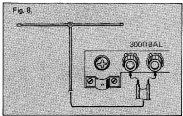
• Connection of FM Antenna
(1) Connect the supplied T-type antenna to the FM 300 Ω terminal on the rear panel.
(2) Fully stretch both edges of the horizontal part and slowly rotate the antenna 180 degrees. Choose the direction that performs the best reception, and fix it on the wall, etc.
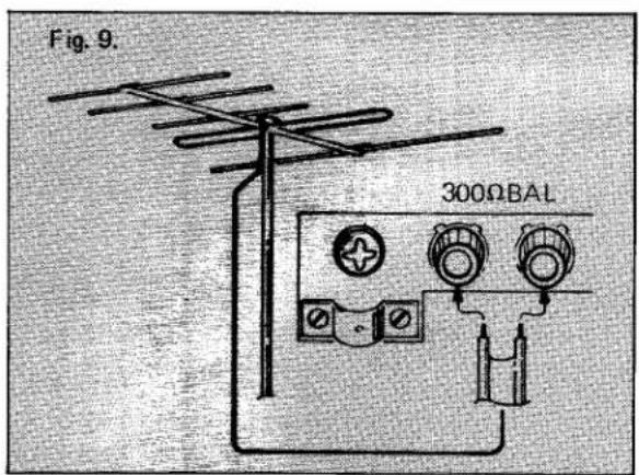
The T-type antenna is used for an area with strong FM signals. If you get poor reception, install a FM antenna matched to the field strength of your location.
There are two impedance (300 Ω and 75 Ω) available for FM antenna input jacks. Either 300 ohms parallel feeder (T-type antenna) or 75 ohms coaxial cable type can be used for connecting a FM antenna.
The 75 ohms coaxial cable is effective if noise such as ignition noise from motorcycles and automobiles affect the sound quality.
• Connection of Coaxial Cable
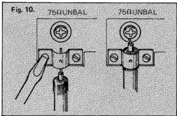
(1) When the cable is to be connected to the 75 Ω terminal, first remove enough of the outer insulation so that some of the outer shield portion can be used for connection. Also strip some of the insulation from the inner core wire.
(2) Loosen the two screws fixing the cable holder, then slip the cable into the holder and tighten the screws so that the holder clamps onto the exposed shield.
(3) Attach the inner core to the 75 Ω terminal.
- FM Reception
(1) Set the SELECTOR switch to "FM AUTO". Make sure TAPE SELECTOR to "SOURCE".
(2) Turn the tuning knob until the desired FM station is reached. Watch the center tuning meter until the pointer is in the middle. This is the optimum tuning point. Remove your hand from the tuning knob and the *T-Locked system will lock onto your desired FM station. When the tuner is locked onto the station, a green T-Locked indicator will light up on the front panel. Your tuning procedure is completed and the T-Locked circuitry will always keep the station locked on.
(3) In stereo broadcasting, stereo indicator light goes on, while it goes off automatically in monaural broadcasting.
(4) If there is excessive noise while listening to FM stereo, switch the selector to FM mono. This will reduce the noise level immensely.
(5) When selecting FM stations, press the FM Muting switch to on and the interstation noise will be eliminated.
\* T-Locked
The circuit capable to fix the optimum tuning point is built in the unit so that the selection may not be off from the accurate tuning point by the change of ambient temperature.
ture if the T-Locked indicator lights up. As long as you are touch with the tuning knob at your finger, the indicator light doesn't go on and T-Locked function is released. Because of the condition of the floor, your shoes or the electro-magnetic shielding effect in the room, the T-Locked indicator may not go off sometimes when you touch the Tuning Knob again. In this case, adjust tuning while touching the front panel. This is nothing abnormal. The circuit is designed to prevent operational mistakes.
USE OF ACCESSORY FUNCTIONS
- Tone Controls
The tone controls are provided for boosting or cutting the volume at low, and high frequencies. This is especially useful since speakers can be compensated to reproduce all frequencies equally. Also, since listening area varies for each uses, the tone controls can compensate various acoustic.
The BASS knob controls the level of the low frequencies, the MIDRANGE knob controls the level of the mid frequencies, and the TREBLE knob controls the level of the high frequencies.
When all the tone controls are set in the 12 o'clock position, the tone control is left out of the signal path so it has no effect on the music. When each knob is turned clockwise from the center position, the level in its respective frequency range is increased, when turned counterclockwise from the center, the level is decreased.
- Filter Switches
Subsonic
Because of low frequency rumble and record warps, the woofer sometimes move unsteadily in and out. Use of the subsonic filter will eliminate this without degrading the sound quality.
With the subsonic switch set to OFF, the main amplifier performs DC operation.
High
High frequency noise, such as tape hiss and record scratches, can be eliminated by use of the high filter.
Balance Control
The balance between left and right volume levels can be affected by differences in the left and right speakers and the arrangement of the furniture in the listening area. Also, some program sources have poor balance between left and right channels. In such a case, the BALANCE knob can be used to provide proper compensation for equal volume levels between left and right channels. When turned counterclockwise, the right channel volume decreases and vice versa. This unit has been factory adjusted so that proper balance can be obtained when the balance knob is
- Loudness Switch
Because the sensitivity of the human ear varies with various levels, a loudness switch is provided to compensate for these change at any volume. When this switch is set to "ON" position, low and high frequencies are emphasized at low volume.
However, when the volume is increased to higher listening levels, the effect of the loudness counter is decreased.
• FM DET. OUT (Detector Output)
Audio signals from FM reception, before they enter the de-emphasis circuit, are present at this DET. OUT. terminal.
If and when a STANDARD 4-channel adaptor is available, it may be connected to this terminal.
• PRE OUT/MAIN IN Terminals
The pre-amp and main amp stages of this equipment may be used independently by simply disconnecting the connector pin from the PRE OUT and MAIN IN terminals.
(1) When the main amp stage only is being used, the only front panel control that will be operable is the SPEAKERS Switch. When, however, only the pre amp stage is being used, all front panel controls, with the exception of the SPEAKERS Switch, will be operative.
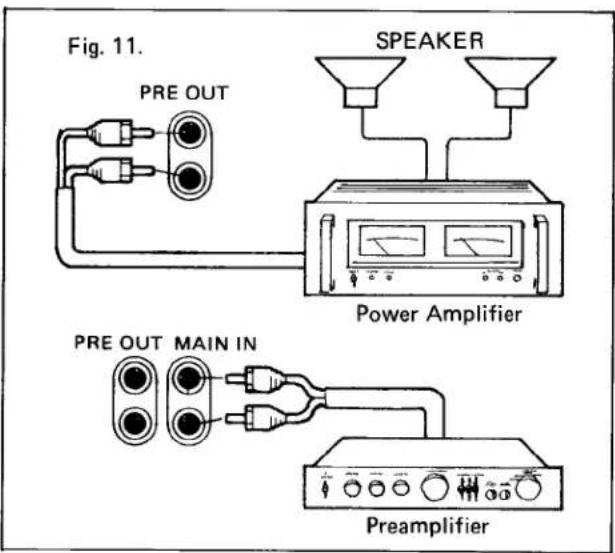
(2) When a channel divider is inserted in between the PRE AMP and MAIN IN terminals, this equipment may be developed into a more versatile multichannel amplifier system.
FM Tuner Section
Usable Sensitivity .....10.3dBf/1.8 μV
50dB Quieting Sensitivity
Mono 13.5dBf
Stereo....35.5dBf
Signal to Noise Ratio
Mono 81dB
Stereo....75dB
T.H. Distortion
Mono 0.07%
Stereo....0.15%
Frequency Response
50Hz to 15kHz....+0.2dB,-0.8dB
Capture Ratio....1.5dB
Alternate Channel Selectivity.....75dB
Spurious Response Ratio .....100dB
Image Response Ratio .....90dB
IF Response Ratio.....100dB
AM Suppression Ratio .....65dB
Stereo Separation
At 1kHz .....48dB
100Hz to 10kHz....35dB
Sub Carrier Product Ratio.....65dB
Muting Threshold .....20dBf
Antenna Impedance....75ohms and 300ohms
Output Level ....550mV, 400Hz 100%
AM Tuner Section
Usable Sensitivity
Ferrite antenna....350 μV/m
Ext. antenna....25 μV
Selectivity 35dB
Signal to Noise Ratio .....50dB
Image Rejection 40dB
IF Rejection.....40dB
Output Level 120mV, 1kHz 30%
T.H.D. 0.3%
Power Amplifier Section
Continuous Power Output
Min. RMS power per channel
into 8ohms from 20 to 20kHz
at rated T.H.D both channels
driven. . . . . . . . . . . . . . . . . . . . . . . . . . . . . . . . . . . . . . . . . 70W + 70W (T.H.D 0.03%)
Both channels driven at 1000Hz. . .80W + 80W (8ohms),
90W + 90W (4ohms)
Intermodulation Distortion.....no more than 0.03%
Total Harmonic Distortion
At rated power into 8ohms....0.03%
Power Bandwidth. IHF....10Hz to 40kHz
Preamplifier Section
Input Sensitivity/Impedance
PHONO....2.5mV/47kohms
AUX....150mV/47kohms
TAPE 150mV/47kohms
PHONO Overload Level .....200mV
Output Level 150mV
Frequency Response
PHONO (RIAA) ....±0.2dB, 30Hz to 15kHz
AUX, TAPE....+0, -1dB, 10Hz to 50kHz
Tone Control
BASS ±10dB (70Hz)
MID RANGE ....±6dB (1kHz)
TREBLE....±10dB (10kHz)
Loudness Control, at -30dB . . . . . . . +8dB (70Hz), +4dB (10kHz)
Filter
SUBSONIC -3dB (20Hz)
-12dB/oct.
HIGH....-3dB (10kHz)
-6dB/oct.
Signal to Noise Ratio, IHF A network
PHONO....84dB
AUX, TAPE....95dB
General
Power Requierment
U.S.A. & Canada Model .....AC 120V 60Hz
European Model . . . . . . . . . . AC 220 \~ 240V
50/60Hz
Power Consumption. . . . . . . . . . . . . . . . . . 320W
Dimensions, W x H x D. 22 x 7 x 15 inches
556 × 179 × 380 mm
Weight, without package....15.5 kg (34.1 lbs.)
*Specifications and design are subject to modifications without notice.
NIKKO ELECTRIC MFG. CO., LTD.
HEAD OFFICE
4-1, Okusawa 3-chome, Setagaya-ku, Tokyo 158, Japan
SALES OFFICE
Mitsubishi Bank Bldg., 3-2. Dogenzaka 1-chome
Shibuya-ku, Tokyo 150, Japan
NIKKO ELECTRIC CORP. OF AMERICA
HEAD CFFICE
16270 Raymer St., Van Nuys, Ca. 91406, U.S.A.
NY OFFICE
320 Oser Ave., Hauppauge, N.Y 11785, U.S.A