C520r - Motionscykel SportsArt - Gratis brugsanvisning og manual
Find enhedens vejledning gratis C520r SportsArt i PDF-format.

Brugerspørgsmål om C520r SportsArt
0 spørgsmål om dette apparat. Besvar dem du kender, eller stil dit eget.
Stil et nyt spørgsmål om dette apparat
Download vejledningen til din Motionscykel i PDF-format gratis! Find din vejledning C520r - SportsArt og tag din elektroniske enhed tilbage i hånden. På denne side er alle dokumenter nødvendige for brugen af din enhed offentliggjort. C520r af mærket SportsArt.
BRUGSANVISNING C520r SportsArt
SPORTSART C520R RECUMBENT BIKE
INTRODUCTION.... 1
IMPORTANT SAFETY PRECAUTIONS
Warning.... 2
Caution.... 2
ASSEMBLING YOUR BIKE
Hardware Kit Contents.... 5
Assembly - Seat Support Covers.... 5
Assembly - Seat Back-Part 1....6
Assembly - Seat Back-Part 2.... 6
Assembly - Seat Back-Part 3.... 7
Assembly - Seat Back Adjust Handle.... 7
Assembly - Screw Inserts.... 8
Assembly - Pedestal 8
Assembly - Seat/Pedal Proximity.... 9
Assembly - Seat Pedal Proximity(Continued).... 10
Assembly - Seat Positioning....11
Assembly - Handlebar....12
Assembly - Cup Holder.... 12
Assembly - Rear Foot Cover....13
Assembly - Horizontal Covers....13
Assembly - Seat Support Covers....14
Assembly - Seat Bottom.... 14
Assembly - Pedals.... 15
Assembly - Levelers....15
Seat Adjustments....16
UNDERSTANDING THE C520R DISPLAY CONSOLE
Display Illustration....17
Specifications....18
Display Overview....18
GETTING STARTED
QUICK START....20
START....20
Setting Up Personal User ID....21
WORKOUT PROGRAMS
TRACK....23
HILL....23
RANDOM....23
INTERVAL (1:1,1:2)....23
WTLOSS & CARDIO....23
ZONE TRAINER....24
COOL DOWN 25
GUIDELINES FOR EXERCISE....25
MAINTENANCE
Clearing User Settings....26
TROUBLESHOOTING
Error Messages....27
INTERNAL SETTINGS
Metric/American standard units....27
Time....27
Distance....28
Display Main Program IC Version....28
WIRING SCHEMATIC....29
SPORTSART C520R RECUMBENT BIKE
INTRODUCTION
Congratulations on your purchase of one of the finest pieces of exercise equipment on the market today, the SportsArt C520R Recumbent Bike. Constructed of high quality materials and designed for years of trouble-free usage, the C520R is built to become an integral part of your fitness regimen.
Before using your new exercise bike, we recommend that you familiarize yourself with this owner's manual. Understanding the correct use of this equipment will enhance your ability to achieve your exercise goals safely and successfully.
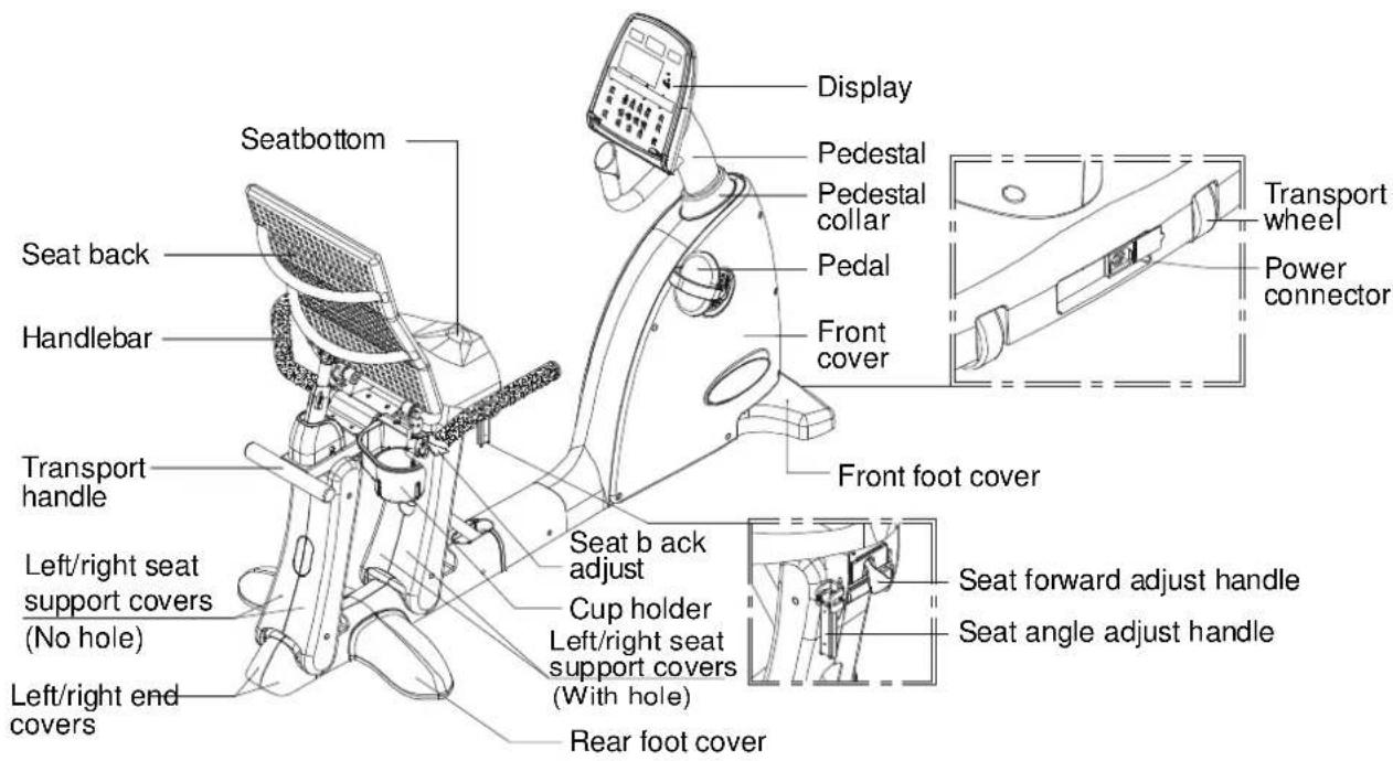
text_image
Seatbottom Seat back Handlebar Transport handle Left/right seat support covers (No hole) Left/right end covers Display Pedestal Pedestal collar Pedal Front cover Front foot cover Seat b ack adjust Cup holder Left/right seat support covers (With hole) Rear foot cover Transport wheel Power connector Seat forward adjust handle Seat angle adjust handleIMPORTANT SAFETY PRECAUTIONS
Your SportsArt bike was designed and built for optimum safety. However, certain precautions apply whenever you use your bike. Please read the entire manual before assembly and operation.
Please read and observe the following safety guidelines:
- Keep this owner's manual for future use and reference.
- Read this owner's manual and follow the instructions.
- Assemble and operate the bike on a solid, level surface.
- Never allow children on or near the bike.
- Check the machine before every use. Make sure all parts are assembled properly and fastened securely. Do not use the bike if it is disassembled in any way.
Warning
- Keep your hands away from moving parts.
- Wear proper workout clothing. Do NOT wear overly loose clothing. Do not wear shoes with leather soles or high heels. Tie all long hair back.
- Do not rock the unit from side to side and take care when mounting and dismounting the unit.
-
Do not stand on the unit.
-
Do not use accessories that are not specifically recommended by the manufacturer as these might cause injuries or cause the unit to fail.
- Allow sufficient space on both sides of the bike for users to mount and to dismount the unit.
- If any parts fail or are defective, please stop your workout immediately and contact your authorized dealer for repairs.
- Work within your recommended exercise level; do NOT work to exhaustion.
- If you feel any pain or abnormal sensations, STOP YOUR WORKOUT. Consult your physician immediately.
- The user weight limit for this bike is 150 kgs (330 lbs). Note: User weight limits differ in different markets.
Caution
Before beginning any exercise program, you should consult your doctor. It is recommended that you undergo a complete physical examination before starting a rigorous exercise regimen.
SAVE THESE INSTRUCTIONS
ASSEMBLING YOUR CYCLE
Before assembling your bike, make sure that you have all of the following items.
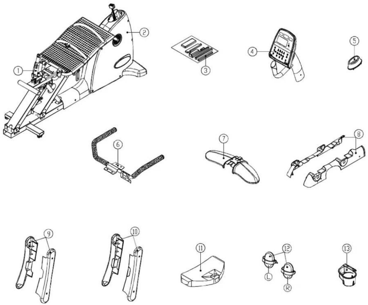
text_image
Technical diagram of a mechanical device with numbered parts for identification and assembly reference.- Gas spring
- Body
- Hardware kit
- Pedestal and display
- Pedestal collar
- Handlebar
-
Rear foot cover
-
Horizontal covers
- Left/right seat support cover (front - with hole)
- Left/ right seat support cover (rear - no hole)
- S eat bottom
- Pedals
- Cup holder
Note: Some screws and washers are secured in the frame. Remove them before trying to assemble the exercise bike.
Hardware Kit Contents
- Open double end wrench, 1 pc
- L-shaped Allen wrench (M5), 1 pc
- L-shaped Allen wrench (M6), 1 pc
- L-shaped Allen wrench (M4), 1 pc
- Screwdriver handle (green), 1 pc
- Double-ended screwdriver stem, 1 pc
- Round head Phillips screws, 10 pc
- Screw inserts, 8 pc
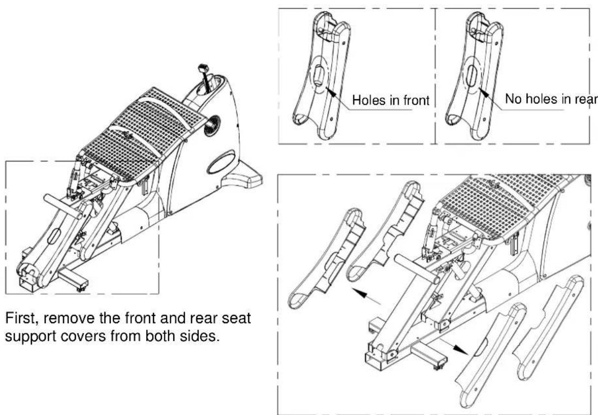
Assembly - Seat Support Covers
Assembly - Seat Back - Part I

natural_image
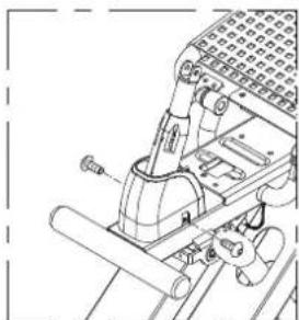
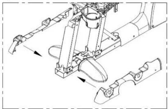
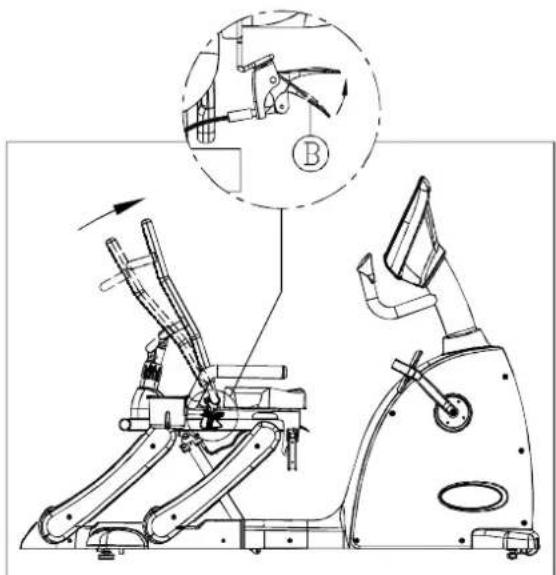
Technical line drawing of a mechanical exercise machine (no text or symbols visible)- Remove the pin and R clip at position A.
- Insert end B of the gas spring into bracket A.

text_image
Technical diagram showing mechanical assembly with labeled components A and B, including a directional arrow and circular indicators.- Secure the gas spring with the pin a n d R c lip.
natural_image
Technical line drawing of a mechanical assembly with no visible text or symbolsAssembly - Seat Back - Part 2

natural_image
Technical line drawing of a mechanical exercise machine (no text or symbols visible)- Set the gas spring cover into place.

natural_image
Mechanical assembly diagram showing a lever mechanism with a load applied (no text or symbols)- Tighten the gas spring cover with screws to secure it.
natural_image
Technical line drawing of a mechanical assembly with no visible text or symbolsNote: Screws are in the hardware kit.
Assembly - Seat Back - Part 3
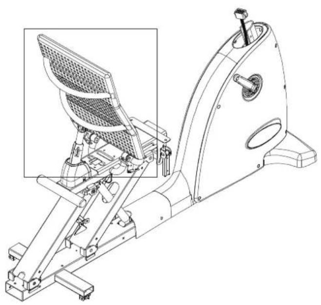
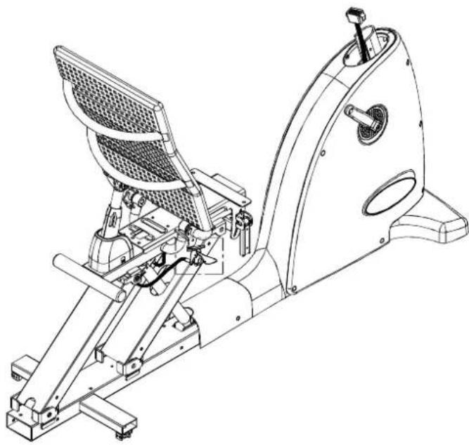
natural_image
Technical line drawing of a stationary exercise machine with internal components and a highlighted inset (no text or labels)- Remove the R clip and gas spring at location C.
- Lift the seat back to position D.
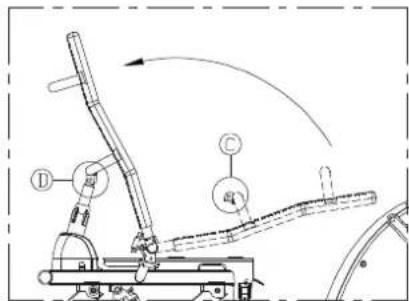
text_image
Technical diagram of a robotic arm with labeled components and motion arrows- Insert the pin and R clip to secure the s eat back.

natural_image
Technical line drawing of a mechanical assembly with no visible text or symbolsAssembly - Seat Back Adjust Handle
natural_image
Technical line drawing of a stationary exercise machine (no text or symbols present)- Secure the seat back adjust handle as shown.

natural_image
Technical line drawing of a mechanical assembly with no visible text or symbolsAssembly - Screw Inserts
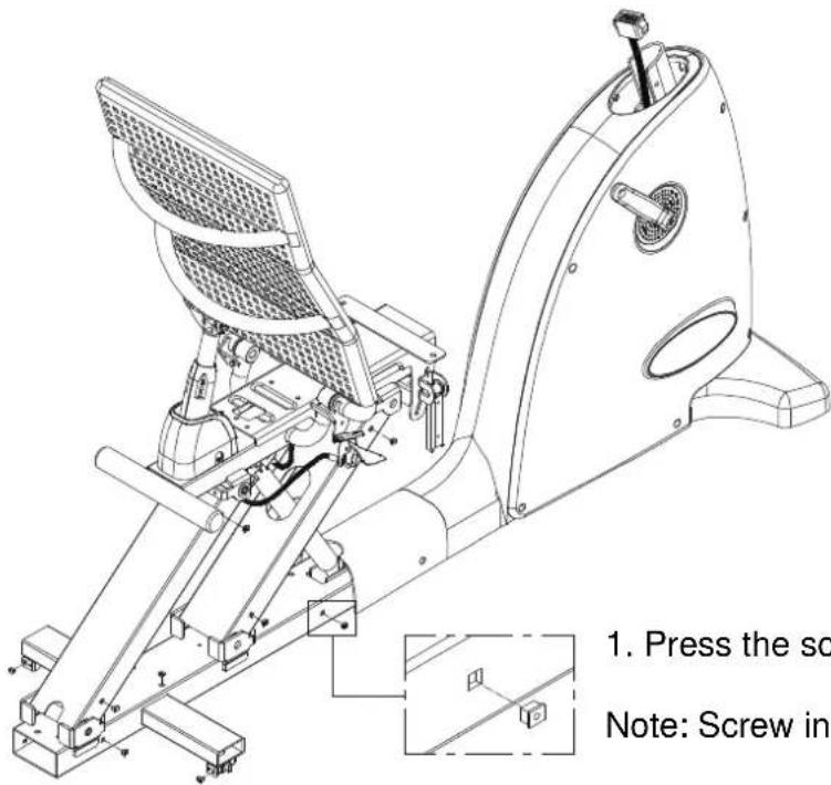
text_image
1. Press the sc Note: Screw ins- Press the screw inserts into the frame.
Note: Screw inserts are in the hardware kit.
Assembly - Pedestal
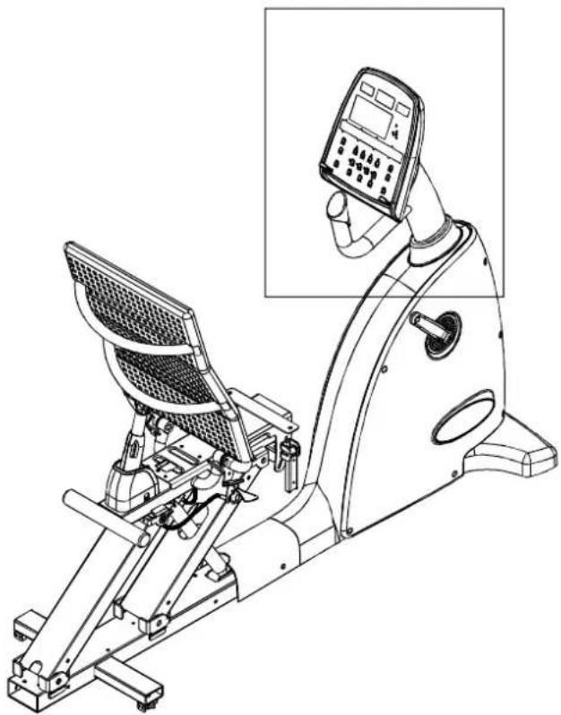
natural_image
Line drawing of a stationary exercise machine with control panel and display screen (no text or symbols)- Put the pedestal collar in place.
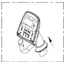
natural_image
Illustration of a handheld electronic device with a hand and scroll, no visible text or symbols- Connect the data cable connectors as shown.
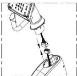
natural_image
Diagram of a robotic arm with a tool inserted, showing mechanical components and motion (no text or symbols)- After connecting the data cable, insert the pedestal into the unit frame. Secure screw/washer set B, then secure set A and set C.

text_image
Diagram of a handheld device with labeled parts A, B, and C indicating different components or functions.Assembly - Seat/Pedal Proximity
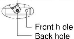
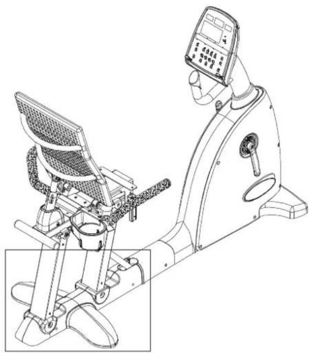
The seat position on C520R can be adjusted to suit people with different leg lengths. The seat position can be altered in two ways: An automatic gas spring moves the seat within a set range; and the placement of the gas spring's connection to the frame changes the range of movement. The frame has front and back holes. Connecting the gas spring at the front hole makes the seat closer to the display. Connecting the gas spring at the rear connection point makes the seat farther from the display. Tall people would probably prefer a set up with the gas spring connected at the back hole. This is the position set at the factory.
To adjust the proximity of the seat to the pedals, follow the instructions below.

natural_image
Technical line drawing of a mechanical device with internal components and directional arrows (no text or symbols)Automatic Adjustment
To use the automatic seat adjustment (gas spring activated), sit on the seat and hold up the handle marked A in the illustration. Push against the pedals and/or handle to move the seat back, or simply let the seat move forward to bring it close to the display. Once the seat moves to the desired position, release handle A. The seat will stay at that position.

natural_image
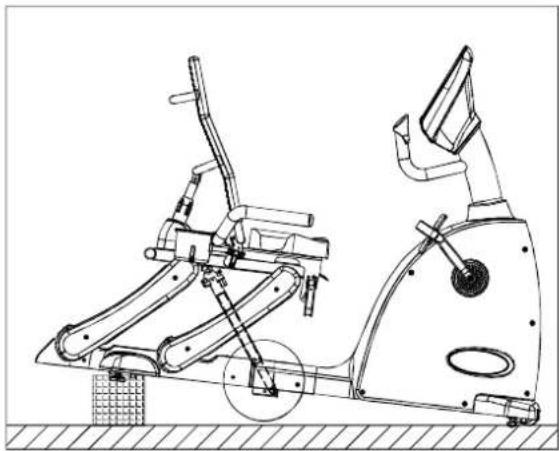
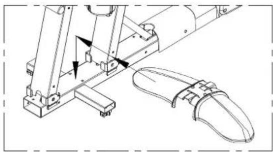
Technical line drawing of a stationary exercise machine with levers and wheels (no text or symbols)Connection Point Adjustment
Follow the instructions below to change the gas spring connection point. Connecting the gas spring to the front hole will place the pedals closer to the display.
First, prop up the back of the bike as shown.
text_image
Front h ole Back holeAssembly Seat Pedal Proximity (Continued)
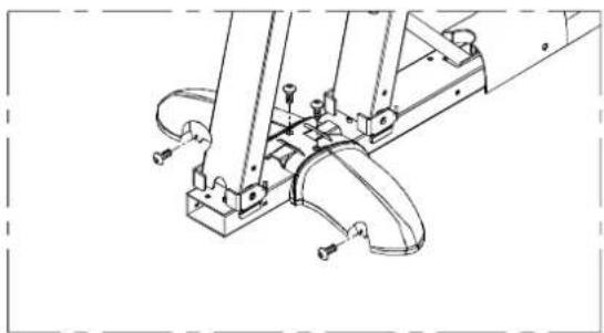
Connection Point Adjustment (Continued)
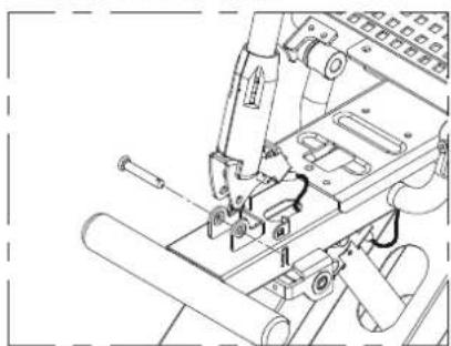
Then, move the shock to the front hole and secure it. Please refer to the instructions and diagrams below.
a. Remove the screw and washer.
b. Tap out the bushing.
c. Move the end of the gas spring to the front hole.
d. Put the bushing through the hole in the frame and past the hole in the gas spring. Secure the washer and screw.
natural_image
Technical line drawing of a stationary exercise machine with levers and wheels (no text or symbols)Q
b.
C.

natural_image
Technical line drawing of a mechanical assembly with a bracket and threaded fastener (no text or symbols)
natural_image
Technical line drawing of a mechanical clamp or bracket assembly (no text or symbols)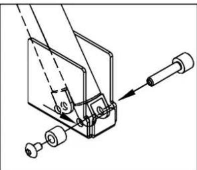
natural_image
Technical line drawing of a mechanical assembly with no visible text or symbolsUse the same process to adjust the connection point again, if desired.
Assembly Seat Positioning
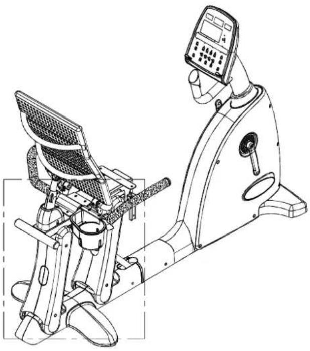
- Locate the handle in position E. Hold up handle F as shown. Do not release the handle.

text_image
Technical diagram of a stationary exercise machine with labeled components and an inset showing mechanical assembly details.- The gas spring will push the seat up so that the handlebar and lower covers can be installed. Release the handle after the seat stops moving.

natural_image
Technical line drawing of a stationary exercise machine with articulated arm and control panel (no text or symbols)Assembly - Handlebar

natural_image
Technical line drawing of a stationary exercise machine with control panel and mechanical components (no text or labels)- Insert the handlebar between the seat back and the gas spring as indicated below. Note: You cannot slide the handlebar in straight. You must tilt and move it to fit it in.

natural_image
Technical line drawing of a mechanical assembly with gears and levers (no text or symbols)- Secure the handlebar with washers and screws provided.
natural_image
Technical line drawing of a mechanical assembly with bolts and components (no text or symbols)Assembly - Cup Holder

natural_image
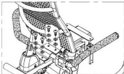
Line drawing of a stationary exercise machine with control panel and display unit (no text or symbols)- Set the cup holder in place and secure it with screws.
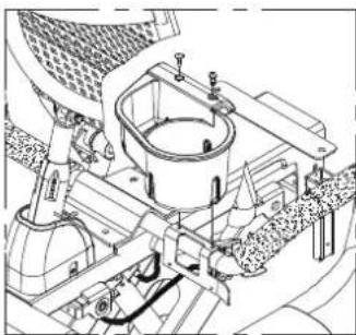
natural_image
Technical line drawing of a mechanical assembly with gears and components (no visible text or labels)- Insert a screwdriver through the slots in the cup holder to secure the screws.

natural_image
Technical line drawing of a mechanical assembly with no visible text or symbolsAssembly - Rear Foot Cover

natural_image
Line drawing of a stationary exercise machine with control panel and footrest (no text or symbols)- Put the rear foot cover in place.
natural_image
Technical line drawing of a mechanical assembly with no visible text or symbols- Loosely secure each screw. After all screws are in place, tighten them down.
natural_image
Technical line drawing of a mechanical assembly with no visible text or symbolsAssembly - Horizontal Covers
natural_image
Line drawing of a stationary exercise machine with control panel and side-mounted device (no text or symbols)- Put left and right horizontal covers in place.
natural_image
Technical line drawing of a mechanical assembly with no visible text or symbols- Loosely secure each screw. After all screws are in place, tighten them down.

natural_image
Technical line drawing of a mechanical assembly with labeled parts (no readable text or symbols)Assembly - Seat Support Covers
natural_image
Technical line drawing of a stationary exercise machine with control panel and side-mounted device (no text or symbols)- Put front and back seat support covers in place.

text_image
Front- with hole Back- No hole- Loosely secure each screw. After all screws are in place, tighten them down.

natural_image
Technical line drawing of a mechanical assembly with no visible text or symbolsAssembly - Seat Bottom

natural_image
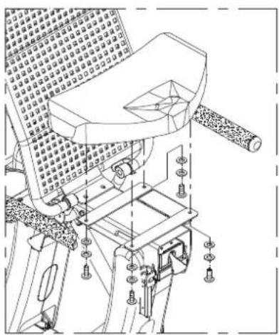
Line drawing of a stationary exercise bike with a grid-patterned seat and leg mechanism (no text or symbols)Secure the seat bottom as shown.
natural_image
Technical line drawing of a mechanical device with no visible text or symbolsAssembly - Pedals

natural_image
Line drawing of a stationary exercise machine with control panel and display unit (no text or symbols)Pedals are marked left or right. Put pedals on the appropriate side. The bike's left/right sides are the same as the user's left/right sides.
Note: the left pedal screws in counterclockwise. The right pedal screws in clockwise. Insert pedals by hand to make sure they thread properly. Then use the wrench to tighten them in place.
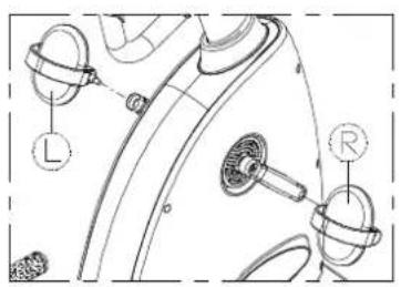
text_image
Technical diagram of a mechanical component with labeled parts L and RAssembly - Levelers
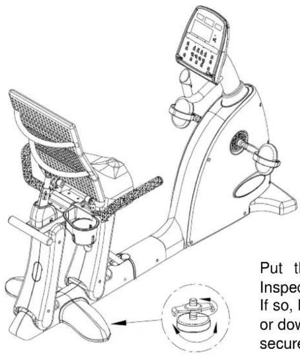
text_image
Put th Inspec If so, I or dow securePut the bike where it will be ridden. Inspect it. Does it rock from side to side? If so, level it. Rotate rubber leveler feet up or down until the bike does not rock. Then secure this position by rotating the leveler nut against the unit frame.
Seat Adjustments

natural_image
Technical line drawing of a mechanical device with internal components and directional arrows (no text or symbols)Up/Down Adjustment
Sit on the seat. Pull up lever A. Adjust the seat position until it suits you. (Push against the pedals to move back, or pull the handle to move forward.) Then release the lever.
natural_image
Technical line drawing of a mechanical exercise machine with an inset showing a mechanical component (no text or symbols present)Seat Back Adjustment
Sit on the seat. Pull up lever B. Adjust the seat back until it reaches a comfortable position. Then release the lever.

natural_image
Technical line drawing of an exercise machine with mechanical components and a magnified inset showing internal structure (no text or symbols)Seat Angle Adjustment
Sit on the seat. Pull lever C up. Adjust the seat angle. Then push lever C down to secure the seat in place.
UNDERSTANDING THE C520R DISPLAY CONSOLE
Display Illustration
text_image
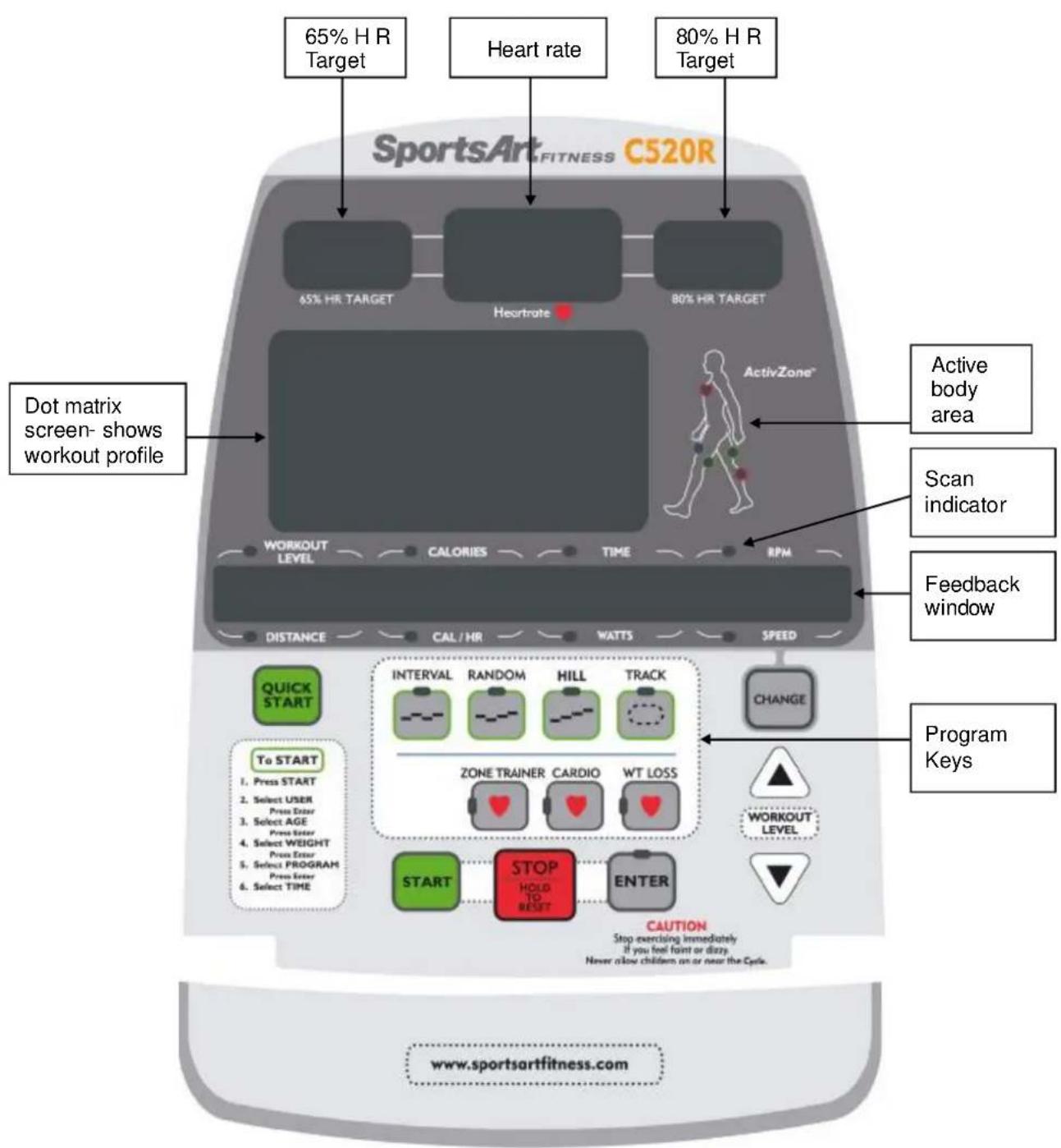
65% H R Target Heart rate 80% H R Target Dot matrix screen- shows workout profile SportsArt FITNESS C520R 65% HR TARGET Heurtrate 80% HR TARGET Active body area Scan indicator Feedback window ActivityZone™ WORKOUT LEVEL CALORIES TIME RPM DISTANCE CAL / HR WATTS SPEED QUICK START To START 1. Press START 2. Select USER Press Enter 3. Select AGE Press Enter 4. Select WEIGHT Press Enter 5. Select PROGRAM Press Enter 6. Select TIME INTervalsAL RANDOM HILL TRACK ZONE TRAINER CARDIO WT LOSS START STOP HOLD TO RESET ENTER CAUTION Stop exercising immediately If you feel faint or dizzy. Never allow children on or near the Cycle. CHANGE PROGRAM Keys WORKOUT LEVEL www.sportsartfitness.comSpecifications
- WORKOUT LEVEL - Resistance range: 1 \~ 20
- TIME - Time range: 00\~99:59; Time setting range: 5:00 \~ 99:00. (After 99:00, 0 appears)
• DISTANCE - 0.1-9999 Km/Mile
• CALORIES - 0\~9999 K-CAL
• CAL/Hr (calories per hour) - 0\~9999 K-CAL - RPM (rotations per minute) - 0\~160 (countable)
• HEART RATE (range) - 40-250 - WATTS - 0\~9999
- SPEED - 0\~55.9 Mile/H / 0\~90 Km/H (1 Km=0.62137 Miles; 1 Mile=1.60935 Km)
- PROGRAM - TRACK, HILL, RANDOM, INTERVAL, WT LOSS, CARDIO, ZONE TRAINER.
- USER - Four user settings including 11 alpha-numeric ID settings
- AGE - 10\~99
- WEIGHT - Setting range: 30 \~ 150 Kg or 66 \~ 330 LB
Note: Throughout this product user manual, display keys and some functions appear in capital letters.
Display Overview
Designed to help you achieve your exercise goals, C520R display has the following windows:
65% HR TARGET - shows the optimum heart rate zone for weight loss.
■ HEART RATE - shows actual heart rate.
■ 80% HR TARGET - shows the optimum heart rate for cardio conditioning.
■ WORKOUT ILLUSTRATION - shows workout profiles and workout prompts.
■ FEEDBACK WINDOW - shows workout prompts and workout feedback.
■ LEDs - light to indicate active programs, active feedback values, scan mode, selection confirmation, and body areas being exercised.
Key Function Overview
CHANGE – Press the CHANGE key while exercising to view a different row of workout feedback. Active feedback indicator LEDs light up. Top row: WORKOUT LEVEL, CALORIES, TIME, RPM. Bottom row: DISTANCE, CAL/HR, WATTS, SPEED. In scan mode, feedback LEDs flash, and a different row of feedback information is displayed every six seconds. Solid feedback LEDs means that the unit is not in scan mode.
QUICK START – Press this key to start exercising without first entering user information. In QUICK START mode, time counts upward; values accumulate.
START – Press this key to start exercising after inputting user information.
EXERCISE PROGRAMS— When these indicators flash, or during a workout program, press an exercise program key to activate that program. When active, the related exercise program indicator lights up.
ENTER – After making a selection, press this key to confirm your choice.
WORKOUT LEVEL (UP & DOWN) – Press these keys to adjust resistance level. Holding down these keys makes resistance adjust up or down faster.
STOP/HOLD TO RESET – This key is used in two ways. If you entered an exercise program after pressing the QUICK START key, press this key to exit the exercise program. If you entered an exercise program after pressing the START key, press this key to select another program. Program indicators will flash. At any time during your workout, hold this key for three seconds to return to the start up banner screen.
GETTING STARTED
The "startup banner screen" appears on the display after you press the START key or the QUICK START key, or if you start pedaling (over 30 RPM). The startup banner shows the message "SPORTSARTC520." Once the startup banner appears, there are two ways to start your workout. Press either QUICK START or START.
QUICK START
The QUICK START key allows you to begin exercising immediately without first setting up a user ID. Using the QUICK START key is a quick and convenient way to start exercising, but it does not convey information, such as your own age and weight, to the display. Consequently, target heart rate and calorie count values shown through QUICK START will not be as accurate as those shown after entering user information.
To start exercising via QUICK START, when the startup banner appears, press the QUICK START key. QUICK START mode uses the default assumption of a 35-year-old, 165-lb/75-kg user to calculate calorie count and target heart rate values. Time counts upward. Resistance starts at level one and can be adjusted during exercise.
Other characteristics of the QUICK START mode include the following:
- Exercise programs can be activated through QUICK START. While exercising, simply press EXERCISE PROGRAM keys or the ZONE TRAINER key to do so. Time counts upward. Resistance can be adjusted at any time.
- When no one pedals on the bike, the message "PEDAL TO START" will scroll across the display every four seconds, after which the start up banner screen will appear.
- If no one pedals after 15 seconds, an energy saving mode is activated. In energy saving mode, all LEDs extinguish except for the feedback window which shows the following:
natural_image
Pure horizontal line with four right-pointing arrows, no text or symbols presentThese lines remain lit for two minutes unless you pedal over 30 RPM. If no one pedals for two minutes, the display automatically shuts off.
START
Use the START key to take advantage of user age and weight in providing more accurate calorie count and target heart rates. Up to four user IDs can be stored in memory and workout time, distance, and calorie expenditure values accumulate for each user.
To operate the bike through the START mode and set up a user ID, follow the instructions below.
When the start up banner appears, press the START key. The display shows the previously used USER ID and accumulated workout statistics. Every six seconds one of the following boxes appears. Here is an example:
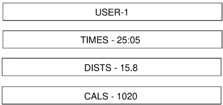
text_image
USER-1 TIMES - 25:05 DISTS - 15.8 CALS - 1020Use any ▲ or ▼ key to toggle through USER IDs. Then press ENTER to confirm your choice.
Setting Up Personal User ID
Like the numbered user IDs, personalized IDs with up to 11 characters can be established. Follow the instructions below to do so.
When a USER ID appears, press the CHANGE key continuously for three seconds. The following prompt appears:
| E | N | T | E | R | I | D |
Press any ▲▼ key to see alphabetical characters. When the letter you want appears, press the ENTER key to confirm your choice. Use the same process again to choose and confirm more characters. When the user name is complete, hold down the ENTER key for three seconds to complete the process.
To revise a user name, choose the USER ID and hold down the CHANGE key for three seconds. Then follow the procedure to establish an alphabetical user ID as explained above. To erase accumulated workout information, simultaneously press STOP+START keys. Accumulated workout time, RPMs, and distance will disappear.
Once you have chosen a USER ID, establish user specifics as follows:
- Age – The age indicator flashes. The dot matrix screen shows the preset value of 35. Press ▲ and ▼ keys until your actual age appears. Then press the ENTER key to confirm your choice and proceed to set the user weight.
User age becomes the basis for calculating target heart rate. 65% and 80% target heart rates represent low and high heart rate targets. AGE setting range is 10 \~ 99. The default age is 35 years old.
- W eight – The WT indicator flashes. KG or LB lights up. KG indicates metric mode, which has a preset value of 75 KG. LB indicates US mode, which has a preset value of 165 LB. Press ▲ and ▼ keys until your actual weight appears. Then press the ENTER key to confirm your choice and proceed to the select a workout program.
Weight setting range is 66 \~ 330 LB / 30 \~ 150 KG. The default setting is 165 LB / 75 KG. User weight is the basis for the calorie expenditure calculation.
- Workout program – Press the workout program key. The related program indicator lights up. Then press the ENTER key to confirm your choice and proceed to set the workout duration.
Note the following characteristics of workout programs:
- Resistance can be changed as you exercise.
- Time starts counting upward when you start pedaling. On the workout illustration, your current stage is represented by the flashing LED.
- You can activate another program while you workout. Time continues to accrue.
-
The ZONE TRAINER key can be pressed during any workout program. This key makes any program a heart rate control (HRC) program. ZONE TRAINER is explained in detail below.
-
Workout duration – The time window shows the previous workout duration setting. Press ▲ and ▼ keys to change the setting. Then press the ENTER key to confirm your choice. The workout begins immediately after you confirm your choice.
WORKOUT PROGRAMS
Workout programs include TRACK, HILL, RANDOM, INTERVAL, and two cardio programs (WEIGHT LOSS and CARDIO). The ZONE TRAINER program turns any program into a cardio program.
TRACK
One lap is 400 meters (0.25 mile). The user can manually adjust resistance and stride.
HILL
The HILL program contains three hill patterns to choose from. A different pattern appears each time the HILL key is pressed: HILL-1, HILL-2, HILL-3.
RANDOM
The RANDOM program contains a random selection of workout patterns. A new pattern appears each time the RANDOM key is pressed.
INTERVAL (1:1, 1:2)
The INTERVAL program is made up of two workout periods, a REST period and a WORK period. Each period contains a different resistance level. There are two REST to WORK ratios to choose from, either 1:1 or 1:2.
In the 1:2 ratio, the first part, 1, is REST= one minute; the second part, WORK= two minutes.
While exercising, a different INTERVAL pattern appears every time INTERVAL is pressed.
Because interval is a two-segment program, once in operation, changing the resistance of a REST or WORK segment carries that setting into the next REST or WORK segment. For instance, if you change a REST period resistance level and commit it to memory, the next REST period will have that same resistance setting. The same applies for WORK Segments.
WT LOSS & CARDIO
These two programs are heart rate control programs. By automatically adjusting resistance, they keep the user's heart rate in a specific target range to accomplish certain exercise goals. One program maintains a heart rate for optimum weight loss. The other program maintains a heart rate for optimum cardio training.
- The weight loss program maintains a heart rate at 65% of your maximum heart rate. The weight loss conditioning formula is (220–AGE) x 65%.
- The cardio conditioning program maintains a heart rate at 80% of your maximum heart rate. The cardio conditioning formula is (220–AGE) x 80%.
At any time during a heart rate control program, if the user's heart rate is not detected, the following message appears: "NO HEART RATE READING, PLEASE CHECK TRANSMITTER". When no heart rate is detected, resistance can only be adjusted manually. When the heart rate control mode starts operating, a message like the one below appears.
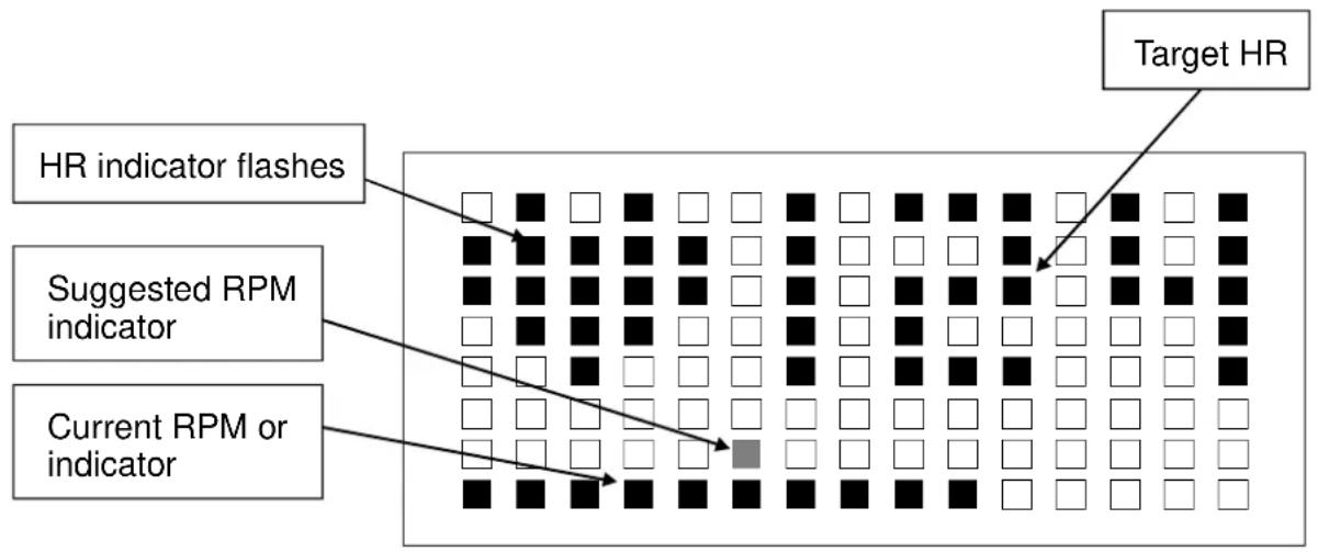
flowchart
graph TD
    A["HR indicator flashes"] --> B["Grid of black dots"]
    C["Suggested RPM indicator"] --> D["Grid of black dots"]
    E["Current RPM or indicator"] --> F["Grid of black dots with one highlighted square"]
    G["Target HR"] --> H["Grid of black dots with white squares"]
The default startup resistance level is LEVEL 1. Suggested speed is 50 RPM. Actual heart rate is shown on the display. When the workout time is reached, the unit enters COOL DOWN mode.
ZONE TRAINER
ZONE TRAINER allows you to select a heart rate and make it your target heart rate. It can be activated from any program. To make a current actual heart rate your target heart rate, press the ZONE TRAINER key at any time. The unit will automatically adjust resistance to maintain the specified target heart rate.
The ZONE TRAINER program can only be entered through another program. It is not accessible if you are not first in another program.
Other aspects of ZONE TRAINER are similar to WT LOSS and CARDIO programs but ZONE TRAINER keeps the previous program's time setting. When the workout time has been obtained, the unit enters COOL DOWN mode.
COOLDOWN
In an exercise program, when the workout time has expired, "ACCU DATA" appears on the display. Accumulated data, including time, distance, calorie expenditure, average heart rate appear. Then "COOL DOWN" appears on the display as the unit enters a two-minute cool down period. When the unit counts down to "0:00", PROGRAM indicators flash, and the "SELECT PROGRAM" prompt appears on the display. Press QUICK START to immediately start exercising, or press START to take advantage of user information.
GUIDELINES FOR EXERCISE
How long should I exercise?
The duration of your exercise session should depend on your fitness level. In general, it is recommended that you maintain your heart rate in the training zone for at least ten minutes to realize an aerobic benefit. As your fitness level increases, you will be able to maintain your heart rate in the training zone for longer periods, usually between 20 and 30 minutes.
When starting your workout, use the first several minutes to warm up, then slowly increase your workload to bring your heart rate into your specific training zone. At the end of your workout, gradually decrease your workload and exercise lightly to "cool down".
How often should I exercise?
To achieve the greatest benefits, perform aerobic exercises three to five times a week. Allow about 24 hours between workouts for your body to recover.
MAINTENANCE
The Sports Art C520R requires little maintenance but regular cleaning is recommended to keep your bike at peak performance. Before your workout, use a dry cloth to clean the surface of the display.
NOTE: NEVER POUR LIQUIDS ON THE DISPLAY.
To clean plastic parts, use a mild detergent, and make sure the unit is completely dry before operating it. Do not use harsh cleaning agents because doing so will void the warranty.
It is recommended that you keep all liquids away from the unit during operation. Spilling liquids onto or into the machine will void the warranty.
Clearing User Settings
When you select a USER ID, the user's accumulated time, distance, and calorie values appear. The user's accumulated time appears as hh:mm (hours:minutes). When the accumulated time exceeds 99:59, minutes disappear; 100 (hours) appears. Maximum time is 9999 hours.
Once the maximum time appears, you must clear the time memory as follows. While the user ID appears on the screen, simultaneously press the STOP and START keys. Hold these keys for three seconds. When the user time, distance, and calorie count values are erased, the display will beep three times. Then you can activate the user ID again.
TROUBLESHOOTING
Error Messages
There are no error messages on this bike.
INTERNAL SETTINGS
Internal settings determine basic operating conditions, for example, units of measure. To access internal settings, at the startup banner『SPORTSARTC520』, press and hold the CHANGE key for three seconds. Then follow the steps below to see and change internal settings.
Metric/American standard units
The feedback window will show the present setting, either one of the following:
American standard
| UNIT-LB |
Metric standard
| UNIT-KG |
Press ▲/▼ keys to toggle from one setting to another. Then press the ENTER key to confirm your choice and proceed to the next setting. You may also press the STOP key to leave this setting.
Time
The total duration of use appears in the feedback window as follows:
| TIME | - | XX | XX | XX | HOUR |
Press the ENTER key to proceed to the next setting. You may also press the STOP key to leave this setting. This setting cannot be changed.
Distance
The total accumulated distance appears in the feedback window. The unit of distance is either in miles or kilometers, depending on the speed setting selected previously. Press the ENTER key to confirm your choice and to proceed to the next setting. You may also press the STOP key to leave this setting.
| D | I | S | T | - | X | X | X | X | X | X | X | K | M |
Activate and Deactivate User Ids
The following prompt appears:
PRESS UP/DN TO ACTIVATE OR DEACTIVATE 4 USER SETTING
Press the ▲/▼ keys as directed. The display toggles between two views.
To enable USER IDs, toggle to the following:
| U | S | E | R | - | I | D | - | O | N |
To disable USER IDs, toggle to the following:
| U | S | E | R | - | I | D | - | O | F | F |
Press the ENTER key to confirm your choice and proceed to the next step.
Display Main Program IC Version
The display shows the display main program IC version as follows:
XXXXXX XX
Example: C520H - 1A
Press STOP key for three seconds to leave this setting.
If the ENTER key is not pressed in six seconds, the feedback window shows the following prompt:
| P | R | E | S | S | E | N | T | E | R |
Wiring Schematic:
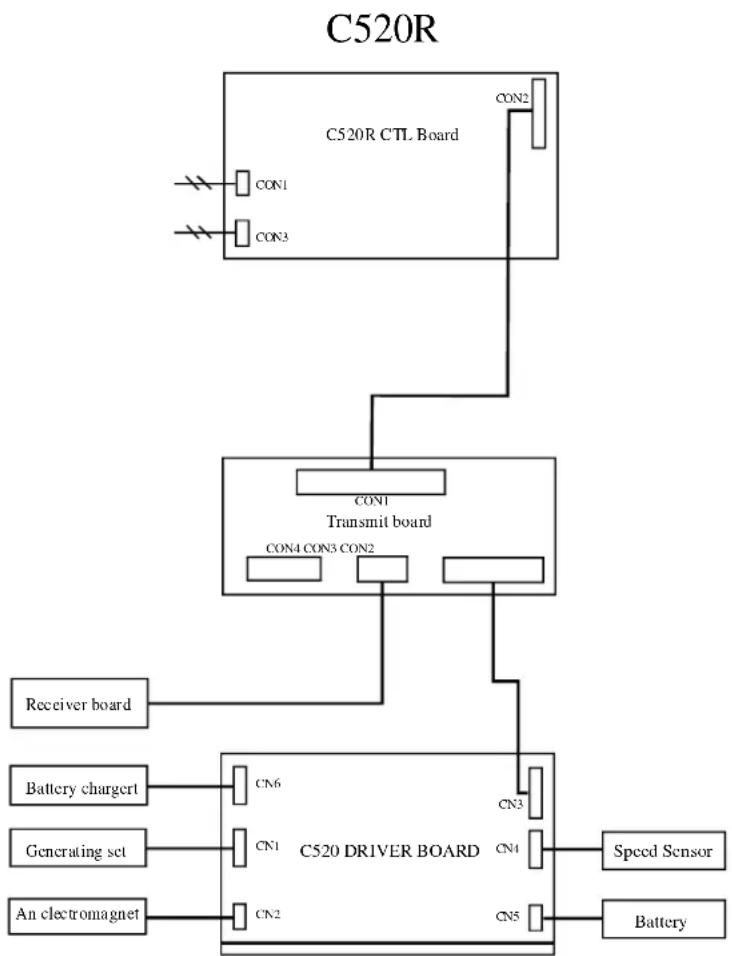
flowchart
graph TD
    A["C520R CTL Board"] --> B["CON1"]
    A --> C["CON3"]
    A --> D["CON2"]
    A --> E["CON1"]
    A --> F["Transmit board"]
    F --> G["CON4 CON3 CON2"]
    F --> H["Receiver board"]
    F --> I["Battery chargert"]
    I --> J["CN6"]
    I --> K["CN1"]
    I --> L["An electromagnet"]
    M["C520 DRIVER BOARD"] --> N["CN3"]
    M --> O["CN4"]
    M --> P["CN5"]
    Q["Speed Sensor"] --> R["Battery"]
Your Authorized SPORTS ART Distributor