
741 - Symaskine Dürkopp Adler - Gratis brugsanvisning og manual
Find enhedens vejledning gratis 741 Dürkopp Adler i PDF-format.

Brugerspørgsmål om 741 Dürkopp Adler
0 spørgsmål om dette apparat. Besvar dem du kender, eller stil dit eget.
Stil et nyt spørgsmål om dette apparat
Download vejledningen til din Symaskine i PDF-format gratis! Find din vejledning 741 - Dürkopp Adler og tag din elektroniske enhed tilbage i hånden. På denne side er alle dokumenter nødvendige for brugen af din enhed offentliggjort. 741 af mærket Dürkopp Adler.
BRUGSANVISNING 741 Dürkopp Adler
741-26;-27
Archiv-ExF D/GB
| Übersicht | Art.-No. | Summary | Art.-No. | |
| Anleitung B+A+S | Instructions for operating, installation and service Instructions f. operating (576) | 4340701 | ||
| Anleitung B (576) | 4340701 | |||
| Anleitung S (576) | Instructions for service (576) Short description of the DA-Microcontrol (GB) | |||
| Kurzbeschreibung der DA-Microcontrol (D) | ||||
| Pn. Geräteplan | Pneumatic circuit plan | |||
| 0797 741016 | 6041140 | 0797 741016 | 6041140 | |
| Bauschaltplan | Interconnection-diagramm | |||
| 9870 741001 B | 5695112 | 9870 741001 B | 5695112 | |
| Stromlaufplan | Circuit-diagram | |||
| 9850 741001 SK | 5672767 | 9870 741001 SK | 5672767 |
DÜRKOPP ADLER AG
Postfach 17 03 51, D-33703 Bielefeld • Potsdamer Straße 190, D-33719 Bielefeld
Telefon (05 21) 5 56-01 • Telex 932 400-0 da d • Telefax (05 21) 5 56 13 15
Art.-No.: 6236855
Teil 1: Bedien- und Aufstellanleitung
1. Bedientafel
1.1 Bedien- und Kontrollelemente des Steuergerätes 3
1.2 Bedienelemente an der Nähanlage/ Wartungseinheit 4
2. Aufstellen der Nähanlage
2.1 Transport der Nähanlage 5
2.2 Transportsicherungen entfernen 6
2.3 Nähkopf montieren 7
2.4 Steuerkasten, Garnständer und Positionsgeber montieren 8
2.5 Allgemeine Sichtkontrolle 9
2.6 Nähanlage elektrisch und pneumatisch anschließen 9
2.7 Erste Inbetriebnahme 10

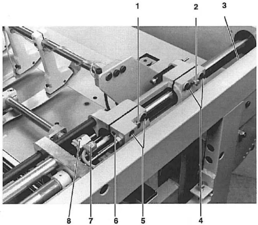
| Dürkopp Adler AG741-26/- 27 | Bedien- und Kontrollelemente des Steuergerätes | ||||
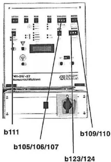
| b100/101 Vorwahlschalter für Programme.Aktivieren durch Stop-Taste b135 oder Hauptschalter AUS-EIN.Beim Eingeben einer unzulässigen Programmnummer zeigt das Display P?P01-P09 NähprogrammeP50-P58 Programme für EinstellhilfenP59-P69 PrüfprogrammeP01 = NähprogrammP05-P09 = Nähen mit vorprogrammierten Knopflochabständen.Schalter "D" und "A" bleiben unberücksichtigt. Programmierung über Programm P50.b111 0 = ohne Funktion1 = Nachnähprogramm9 = Nadelfadenwächter abgeschaltetn1 Anzeige Fadenrißb131 Wenn "b11" in Stellung "0" ist (Nähstellung) kann der Nähkopf in die Servicestellung gefahren werden.b102 Umlauf. Knopfloch einmal oder zweimal Umnähenb132 Rückstellen des im Display angezeigten Stückzählerstandes auf 0000. Bel Hauptschalter AUS bleibt der Zählerstand erhalten.b135 Stop-Taste zum Unterbrechen des Betriebsablaufes und zum Wechseln der mit b101 und b102 eingestellten ProgrammeDisplay Anzeige bei ungestörtem Betrieb:Z.B. 0231 P01Links Stückzählerstand - rechts Programm Nr.. Bel einem Bedienfehler oder einer Störung wird der Funklonsablauf unterbrochen und die Ursache durch Symbol angezeigt. Nur nach Beseltigen der Störung und Anzeige Stückzählerstand kann neu gestartet werden.Display Anzeigen bei Bedienungshilfenp? unzulässiges Programm gewählt741C02 ProgrammnummerSTRT ERR Taster "Start links" (b30) oder "Start rechts"(b319 war beim Starten der Maschine betätigtH=0000 Unterfadenvorrat, SpulenwechselGEBER Positionsgeber nicht angeschlossenS-REF Schrittverluste am SchrittmotorYYYY Nachnahen einzelner KnopflöcherA*D unzulässiger Abstand oder unzulässige Knopflochanzahl eingestelltREFERENZ Maschine befindet sich nicht in Grundstellung | [NK OBEN Nähkorb obenNK UNTEN Nähkorb untenUMGE Schalter "umgekehrtes Nähen" (b126) In unerlaubter Schalterstellung?? U ?? Schalter "Umlauf" (b102" befindet sich in einer unzulässigen Schalterstellung?? ST ?? Schalter "Softstart" (b104) befindet sich in einer unzulässigen Schalterstellung<--> Endstellung suchenDisplay Anzeigen bei StörungenE2 Sicherung e2 defekt | b103 0 = Einlegen mit abgesenkter Anlege-schiene1 = Einlegen mit angehobener Schiene2 = Einlegen mit angehobener Schiene, "Ansaugen Nähgut" eingeschaltet3 = Einlegen mit angehobener Anlege-schiene, "Ansaugen Nähgut" und "Blasen Nähgut" eingeschaltetb104 Softstart0 = nein1 = jab109/110 Knopflochanzahlb123/124 Verschiebung des ersten Knopflochabstandesb105/106/107 Knopflochabstand von 30 - 125 mmb119 Drehzahlb133 Linkslauf <-b134 Rechtslauf ->Schalter Nähanlage EIN-AUS schaltenSchalter Schrittmotorsteuerung EIN-AUS'STOP Prog ERR Fehler bei den abgespeicherten Ab-<<--> TransportfehlerB22 Klemmvorrichtung nicht in Grund-B23 Tisch nicht in EinlegepositionB26 Ausstreifer nicht vornB27 Ausstreifer nicht in GrundstellungSM ERR Schrittmotorfehler, Sicherung überprüfenXRAM Fehler beim Zurücklesen des externen RAMsPOS-ERR Motor dreht sich nicht, Motorschutzschalter überprüfen |  | ||
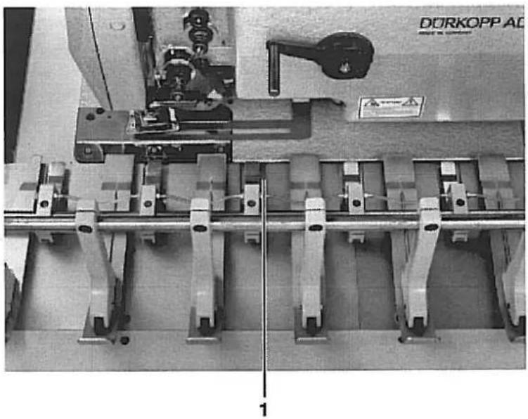
| Dürkopp Adler AG741-26/- 27 | Bedienelemente an der Nähanlage/ Wartungseinheit | |||
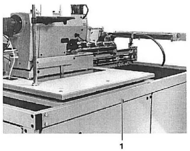
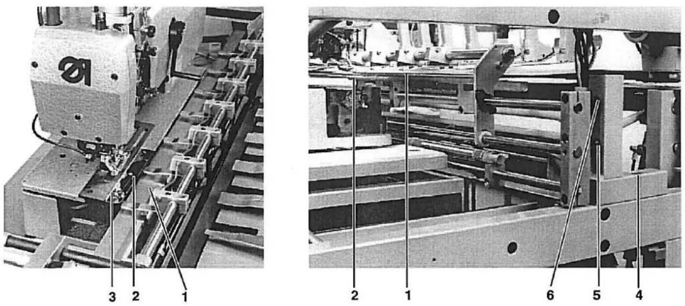
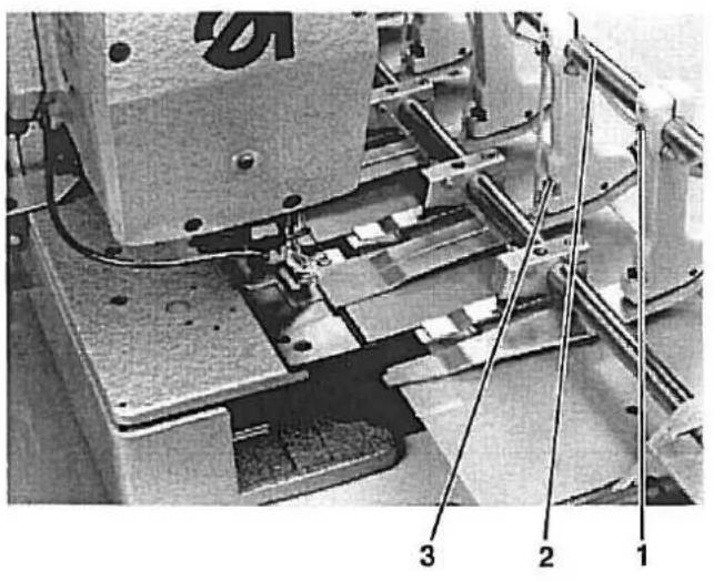
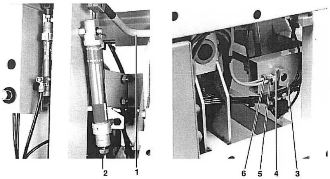
Bedienen | Wartungseinheit[IMAGE] | |||
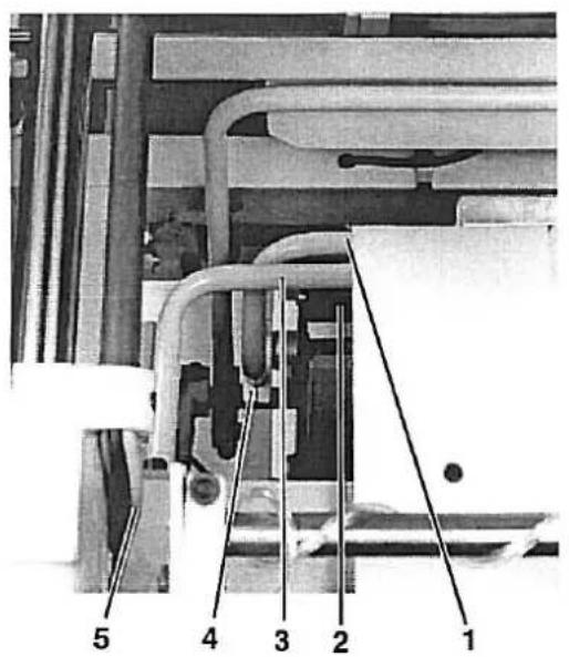
| 1 | Lampe | Anzeige von FadenrißQuiltungssignal auf das Betätigen der Tasten 5. (Überlappende Arbeitsweise) | 3 | NebelöferMit der Regulierschraube 1 ca. 1 Tropfen für 10 Arbeitsspiele einstellen. Zum Nachfüllen die Druckluftzufuhr unterbrechen und das System mit Schraube 7 entlüften. Schraube 2 herausdrehen und Öl der Sorte "Esso SP NK 10" bis zur Rille im Glas nachfüllen. |
| 2 | Microcontrol-Steuerung | Elemente siehe Rückseite | ||
| 3 | Ablagetisch | Ablage der Nähteile | 4 | DruckreglerDruckluftversorgung ohne Öl für die Stoffklemmen der Übergabestation. Zur Einstellung von 4 bar Hülse 5 nach oben ziehen und entsprechend verdrehen. |
| 4 | Blaspistole | Ausblasen von Flusen und Staub | ||
| 5 | Schalter | Zum Einschalten des Nähvorganges. Linken oder rechten Schalter betätigen | ||
| 6 | Hebel | Verstellen der Höhe des Stoffanschlagwinkels | 6 | Luftfilter und WasserabschelderBevor der Wasserstand den Filter erreicht, die Schraube 7 zum Wasserablassen entsprechend weit hereindrehen. Druckluftzufuhr dabeinichtunterbrechen. |
| 7 | Schalter | Entlasten der Staplerklemme zum Entnehmen des Nähgutes | ||
| 8 | Skala | Anzeige der Einschiebetiefe der Übergabestation | 8 | DruckreglerZur Einstellung von 6 bar Hülse 9 nach oben ziehen und entsprechend verdrehen. |
| 9 | Drehknopf | Einstellen der Einschiebetiefe der Übergabestation = Distanz Knopfloch zur Leistenkante | 8 | DruckreglerZur Einstellung von 4 bar Hülse 5 nach oben ziehen und entsprechend verdrehen. |

741-26/- 27
| b103 | 0 = Feed with lowered positioning rail1 = Feed with raised rail2 = Feed with raised rail,"Material Suction" switched on3 = Feed with raised positioning rail, "MaterialSuction" and "Material Blowing" switched on |
| b104 | Softstart0 = no1 = yes |
| b109/110 | Buttonhole number |
| b123/124 | Displacement of the first buttonhole interval |
| b105/106/107 | Buttonhole interval between 30 - 125 mm |
| b119 | Rpm |
| b133 | Run to the left <- |
| b134 | Run to the right -> |
| Switch | Turn the sewing unit ON-OFF |
| Switch . | Step motor control ON-OFF |
| STOP | Stop key defective |
| PROG ERR | Error in the memory stored intervals |
| <<-->>> | Transport error |
| B22 | Clamp not in the base position |
| B23 | Table not in the feed position |
| B26 | Remover not forward |
| B27 | Remover not in base position |
| SM ERR | Step motor fault, check fuse |
| XRAM | Error in downloading the external RAM |
| POS-ERR | Motor not turning, check the motor protection switch |
| NK OBEN | Sewing basket up |
| NK UNTEN | Sewing basket down |
| UMGE | "Reverse Sewing" switch (b126) in an invalid switch setting |
| ?? U ?? | "Overcast" switch (b102") is in an invalid switch setting |
| ?? ST ?? | "Softstart" switch (b104) is in an invalid switch setting |
| ? min-1 | "Rpm" switch (b119) is in an invalid switch setting |
| <--> | Search for the end position |
| Displays for Malfunctions | |
| E2 | Fuse e2 defective |
| b100/101 Pre-selector Switch for Programs.Activated by Stop key b135 or main switch ON-OFF. When an invalid program number is entered the display shows P? | |
| P01-P09 Sewing programs | |
| P50-P58 Programs for setting aids | |
| P59-P69 Testing programs | |
| P01 = Sewing program | |
| P05-P09 = Sewing with pre-programmed buttonhole intervals.Switches "D" and "A" remain disregarded.Programing via Program P50. | |
| b111 0 = no' function1 = Successive sewing program9 = Needle thread monitor off | |
| n1 Display thread break | |
| b131 When "b11" is in position "0" (sewing position) the sewing head can be run into the service position | |
| b102 Circulation. Buttonhole overcast once or twice | |
| b132 Re-setting the piece number shown in the display to 0000. With the main switch OFF the the counter number remains. | |
| b135 Stop key to interrupt the operating sequence and to change the program set with b101 and b102 | |
| Display Display by fault-free operation:e.g. 0231 P01Left piece count - right program no.. During an operating fault or malfunction the function sequence is interrupted and the cause shown by a symbol. Only after correction of the malfunction and display of the piece count can the unit be re-started. | |
| Displays for Operating Aids | |
| p? Invalid programm selected | |
| 741C02 Program number | |
| STRT ERR "Start left" (b30) or "Start right"(b31) key was operated when starting the machine | |
| H=0000 Bobbin thread reserve, bobbin replacement | |
| GEBER Synchronizer not connected | |
| S-REF Step losses at the step motor | |
| YYYY Successive sewing individual buttonholes | |
| A*D Invalid interval or invalid number of buttonholes set | |
| REFERENZ Machine is not in the base position |
Operation
Maintenance Unit
Lamp
3

Oil mister
With the regulating screw 1, set at approx. 1
compressed air supply and vent the system with screw 7. Screw out screw 2 and fill "Esso SP NK 10" oil up to the groove in the glass.
Oil-free compressed air supply for the
material clamps at the transfer station. To set at 4 bar pull sleeve 5 up and turn appropriately. Before the water level reaches the filter turn in screw 7 far enough to drain the water.
Do not interrupt the compressed air su
To set at 6 bar pull sleeve 9 up and
turn appropriately.
To set at 4 bar pull sleeve 5 up and turn appropriately.
With the regulating screw 1, set at approx. 1
Pressure regulator
Air filter and water sepera
Pressure regulator
Pressure regulator
3
3
With the regulating screw 1, set at approx. 1
compressed air supply and vent the system with screw 7. Screw out screw 2 and fill "Esso SP NK 10" oil up to the groove in the glass.
Oil-free compressed air supply for the
material clamps at the transfer station. To set at 4 bar pull sleeve 5 up and turn appropriately. Before the water level reaches the filter turn in screw 7 far enough to drain the water.
Do not interrupt the compressed air su
To set at 6 bar pull sleeve 9 up and
turn appropriately.
To set at 4 bar pull sleeve 5 up and turn appropriately.
With the regulating screw 1, set at approx. 1
compressed air supply and vent the system with screw 7. Screw out screw 2 and fill "Esso SP NK 10" oil up to the groove in the glass.
Oil-free compressed air supply for the
material clamps at the transfer station. To set at 4 bar pull sleeve 5 up and turn appropriately. Before the water level reaches the filter turn in screw 7 far enough to drain the water.
Do not interrupt the compressed air supply.
To set at 6 bar pull sleeve 9 up and
to separate turn appropriate.
To set at 4 bar pull sleeve 5 up and turn appropriately.
With the regulating screw 1, set at approx. 1
compressed air supply and vent the system with screw 7. Screw out screw 2 and fill "Esso SP NK 10" oil up to the groove in the glass.
Oil-free compressed air supply for the material clamps at the transfer stallon. To set at 4 bar pull sleeve 5 up and turn appropriately. Before the water level reaches the filter turn in screw 7 far enough to drain the water.
Do not interrupt the compressed air supply.
To set at 6 bar pull sleeve 9 up and
to separate turn appropriate.
To set at 4 bar pull sleeve 5 up and turn appropriately.
With the regulating screw 1, set at approx. 1
compressed air supply and vent the system with screw 7. Screw out screw 2 and fill "Esso SP NK 10" oil up to the groove in the glass.
Pressure regulator Oil-free compressed air supply for the
material clamps at the transfer station. To set at 4 bar pull sleeve 5 up and turn appropriately. Before the water level reaches the filter turn in screw 7 far enough to drain the water.
Do not interrupt the compressed air supply.
To set at 6 bar pull sleeve 9 up and
to separate turn appropriate.
To set at 4 bar pull sleeve 5 up and turn appropriately.
With the regulating screw 1, set at approx. 1
compressed air supply and vent the system with screw 7. Screw out screw 2 and fill "Esso SP NK 10" oil up to the groove in the glass.
material clamps at the transfer station. To set at 4 bar pull sleeve 5 up and turn appropriately. Before the water level reaches the filter turn in screw 7 far enough to drain the water.
Do not interrupt the compressed air supply.
To set at 6 bar pull sleeve 9 up and
to certain turn appropriate.
To set at 4 bar pull sleeve 5 up and turn appropriately.
With the regulating screw 1, set at approx. 1
With the regulating screw 1, set at approx. 1
With the regulating screw 1, set at approx. 1
With the regulating screw 1, set at approx. 1
With the regulating screw 1, set at approx. 1
With the regulating screw 1, set at approx. 1
With the regulating screw 1, set at approx. 1
2. Aufstellen der Nähanlage
2.1 Transport der Nähanlage
natural_image
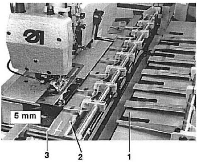
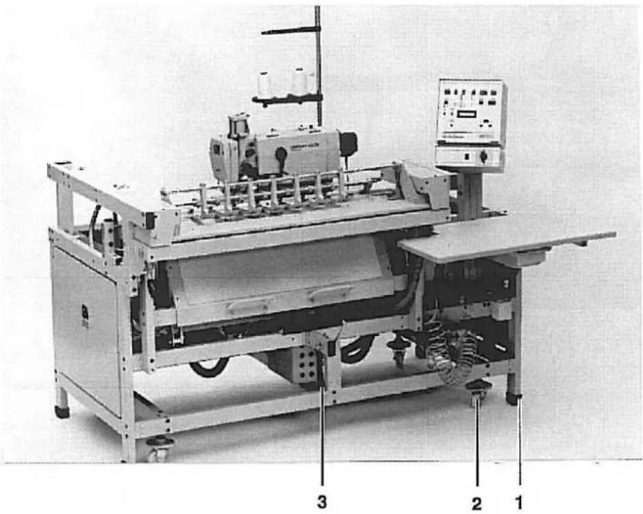
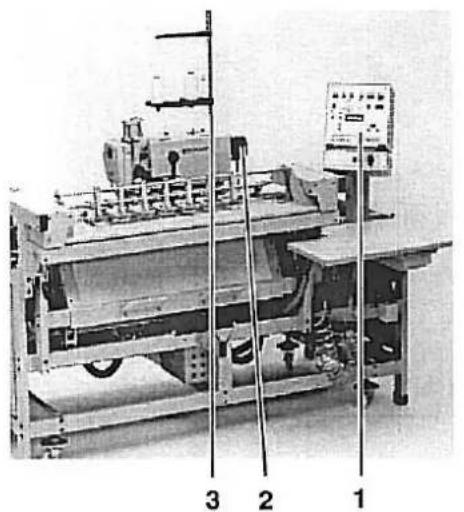
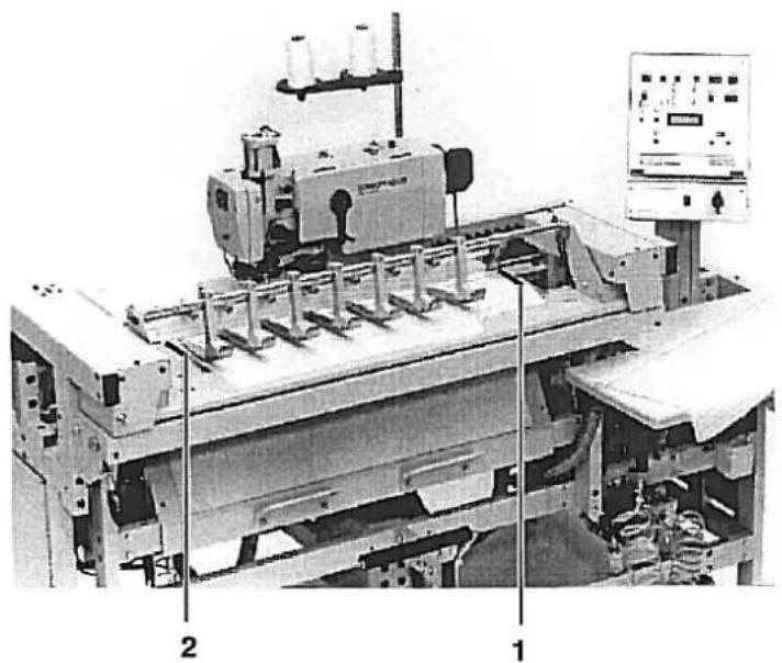
Industrial machine with control panel and labeled parts (1, 2, 3), no visible text or symbols on the device itself.Die Nähanlage ist mit 4 Transportrollen 2 ausgestattet. Diese Transportrollen sind jedoch nur für kurze Transportwege, z. B. innerhalb des Bandes etc., gedacht. Längere Transporte führen Sie bitte mit einem Hubwagen durch.
Nähanlage von der Palette heben.
- Staplergabeln von rechts bis unter die Strebe 3 schieben
- Nähanlage abheben.
Montierte Nähanlage transportieren

Vorsicht Verletzungsgefahr!
Nähkopf kann sich beim Transport verschieben und dadurch das Gewicht verlagern. Nähanlage kann vom Hubwagen fallen.
Steht die Nähanlage an ihrem Einsatzort, sollen die Transportrollen 2 soweit heraufgedreht werden, daß die Nähanlage auf allen vier Füßen 1 steht.
2.1 Transportsicherungen entfernen
natural_image
Industrial machine with articulated arm and control panel (no visible text or symbols)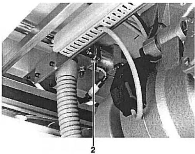
natural_image
Close-up of a mechanical assembly with hoses and components, no visible text or symbols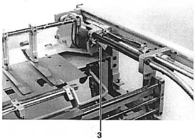
natural_image
Mechanical assembly diagram showing a frame with rollers, brackets, and a numbered component (no readable text or symbols)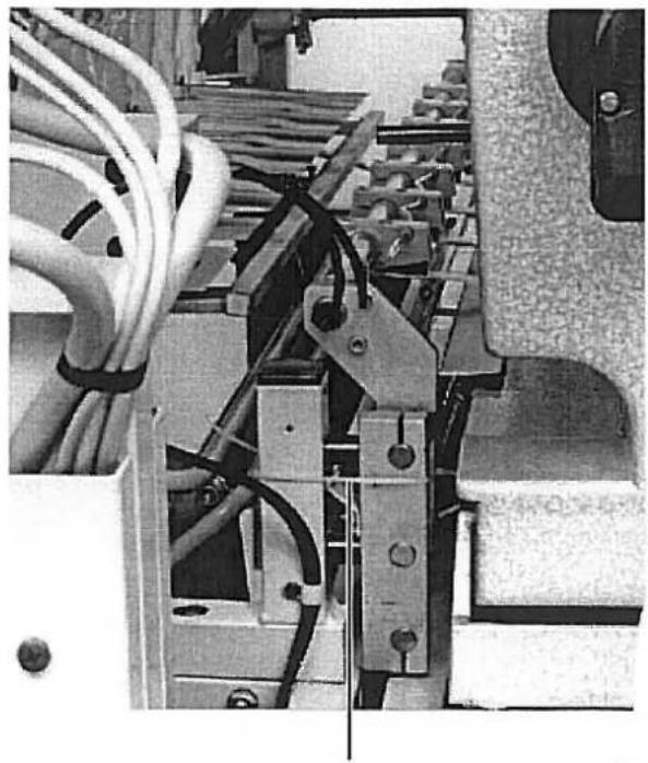
natural_image
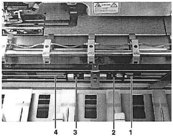
Close-up of electrical wiring and mechanical components (no visible text or symbols)Die Nähanlage ist mit vier Transportsicherungen versehen:
- Sicherung des Nähkopfschlittens in Längsrichtung durch Schraube 1
- Sicherung des Nähkopfschlittens in Querrichtung durch Schelle 2
- Sicherung der Übergabestation durch Schelle 3
- Sicherung der Klemmstation durch Schellenband 4
Entfernen Sie alle 4 Transportsicherungen, bevor Sie die Nähanlage in Betrieb nehmen.
2.2 Linke und rechte Endstellung des Nähkopfes
natural_image
Industrial machine with mechanical components and wiring (no visible text or symbols)
Um die volle Nählänge der Anlage auszunutzen soll der Nähkopf-schlitten so weit wie möglich an den linken und rechten Anschlagring 1 heranfahren.

Vorsicht Verletzungsgefahr!
Nicht in den Fahrbereich des Nähkopfes greifen.
- Testprogramm P58 wählen
- Schalter 3 (b18) und 4 (b20) etwas dichter zusammenschieben
- Nähkopf in die rechte bzw. linke Endstellung fahren.
- Schalter 3 (b18) und 4 (b20) schrittweise nach außen verschieben, bis der Schlitten in der jeweiligen Endstellung leicht gegen den Anschlagring 1 fährt.
- Abstand der Schalter 4 und 5 sowie 2 und 3 auf 110 mm einstellen. (Mitte/Mitte gemessen)
2.3 Nähkopf / Positionsgeber montieren
Der Nähkopf wird in den bereits montierten Sockel eingesetzt. Die erforderlichen Schrauben befinden sich im Beipack.
Vorsicht Verletzungsgefahr!
Den Nähkopf mit Kran oder zwei Personen einsetzen. Quetschgefahr.
- Nähkopf einsetzen und mit zwei Schrauben 7 sichern.
- Nähkopf anheben und die beiden Stoßdämpfer 1 und 3 in den Halterungen festschrauben.
- Verbindungslasche 6 (am Nähkopf mit Schellenband befestigt) mit Schraube am Hebel 5 festschrauben.
- Elektro- und Pneumatikanschlüsse 2 und 4 herstellen.
- Nähkopf herunterlassen.
- Positionsgeber montieren. Einstellung siehe Betriebsanleitung Klasse 576.
mete deite dauwach.
natural_image
Industrial machine setup with control panel and labeled components (no readable text or symbols)
natural_image
Close-up of mechanical components with hoses and tubing, no visible text or symbols
natural_image
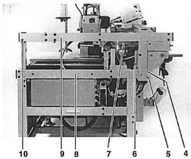
Electrical control panel with multiple switches and cables, no visible text or symbolsDie Steuerkastenanschlüsse sind mit unterschiedlichen Steckersystemen ausgerüstet. Ein vertauschen der Anschlüsse ist damit ausgeschlossen.
Im Garnständerrohr ist eine Hinweislampe installiert. Sie signalisiert z. B., daß der Spulenvorrat zuende ist bzw. bei Mehrplatzsystemen, ob der Nähauftrag ausgelöst wurde.
- Steuerkasten 1 montieren und Steckverbindungen 5 herstellen.
- Garnständer 3 montieren und Steckverbindung 4 herstellen.
- Positionsgeber 2 montieren. Die Einstellung der Positionen entnehmen Sie bitte der Serviceanleitung Klasse 576 Seite 31.
2.5 Allgemeine Sichtkontrolle
Führen Sie eine allgemeine Sichtkontrolle an der Nähanlage durch.
Sind durch den Transport eventuell:
- Teile abgebrochen,
- Teile offensichtlich schief oder verstellt.
-
2.6 Nähanlage elektrisch und pneumatisch anschließen

Zur besonderen Beachtung!
Netzspannung und die auf dem Motortypenschild angegebene Nennspannung müssen übereinstimmen.
Alle Arbeiten an der elektrischen Ausrüstung sind nur von dazu befugten Personen auszuführten und bei herausgezogenem Netzstecker vorzunehmen.
Beachten Sie die allgemeinen Sicherheitshinweise.
natural_image
Industrial pressure regulator device with dual gauges and tubing (no visible text or labels)
natural_image
Industrial machinery setup with coiled pipes and a cylindrical component (no visible text or symbols)- Schlauch der Nähanlage mit dem Druckluftnetz (7-10 bar) verbinden
- Stecker der Nähanlage mit dem Netz verbinden.
- Dabei beachten, daß der Betrieb nur mit dem auf dem Typenschield angegebenen Anschlußwert erlaubt ist.
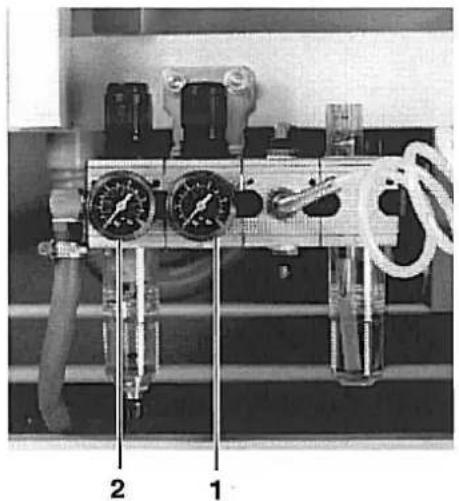
- Betriebsdruck von 6 bar am Druckregler 2 und 4 bar am Druckregler 1 einstellen.
- Nähanlage einschalten und Drehrichtung des Motors kontrollieren.(Siehe Foto). Dreht der Motor verkehrt herum, sind 2 Phasen im Netzstecker entsprechend umzuklemmen.
natural_image
Industrial machine setup with labeled components (1, 2), no visible text or symbols on the machinery itself.Probelauf
Führen Sie zunächst einen Probelauf ohne Nähgut durch, um die richtige Einstellung des Positionsgebers zu prüfen.
- Schalter b111 auf 9 stellen. Fadenwächter ist ausgeschaltet.
- Schalter b109/110 auf 01 stellen. Ein Knopfloch wird genäht.
- Schalter b105/106/107 auf 30 stellen. Minimaler Knopflochabstand.
- Nähanlage starten.
- Stopposition des Nähkopfes prüfen und gegebenenfalls Positionsgeber korrigieren. Sie Serviceanleitung Klasse 576 Seite 31.
Anlegemarkierungen links und rechts
Beispiel:
Das erste Knopfloch soll den geringsten zu nähenden Abstand z. B. 5 cm zur oberen Stoffkante haben.
- Nähkopf in die linke Ausgangsposition fahren.
- Nähgut so anlegen, daß von Stoffoberkante bis zur Nadel ca: 5 cm Abstand liegen.
- Markierung 2 auf der Stoffauflage der Übergabestation anbringen.
- Nähanlage einschalten.
- Nähvorgang durchführen.
- Am fertig genähten Teil den Abstand prüfen und gegebenenfalls die Markierung 2 korrigieren.
- Rechte Markierung 1 wie oben beschrieben anbringen.
Eine Verschiebung des ersten Knopfloches kann mit Schalter b123/124 erfolgen.
Teil 2: Serviceanleitung Vorschubgerät
- Allgemeines 3
1.1 Entfernen der Verkleidungsbleche und Faltenbalge 3
- Vorschubgerät einstellen
2.1 Vordere und hintere Endstellung des Nähkopfes 4
2.2 Linke und rechte Endstellung des Nähkopfes 5
2.3 Klemmstation
2.3.1 Horizontale und vertikale Ausrichtung der Klemmstation/ Abstand zum Nähkopf 6
2.3.2 Ausrichten des Blasrohres und der Stoffklemmen 7
2.3.3 Grundstellung der Klemmstation 8
2.3.4 Dämpfer und Schalter für die Grundstellung 9
2.4 Übergabestation
2.4.1 Horizontale und vertikale Ausrichtung der Übergabestation 10
2.4.2 Führungkloben der Übergabestation 11
2.4.3 Vordere und hintere Endstellung der Übergabestation/ Ausrichten der Stoffklemmen ..... 12
2.5 Stoffanschlag einstellen 13
2.6 Stapler
2.6.1 Stellung von Klemmhebel und Klemmrohr zum Stapelgutträger 14
2.6.2 Stellung des Klemmhebels zum Ausstreifer 15
2.6.3 Ausstreiferbewegung 16
2. Vorschubgerät einstellen
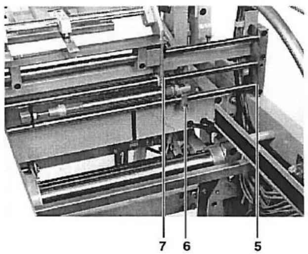
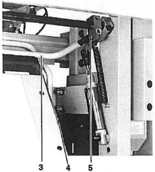
2.1 Vordere und hintere Endstellung des Nähkopfes
Der Zylinder 9 schiebt den Nähkopf in die Positionen (A) und (B). Position (A) wird beim Nähen eingenommen, Position (B) bei Service-arbeiten am Nähkopf.
In Position (A) soll das Auflageblech 1 der Klemmstation einen Abstand von 1 mm zur hinteren Kante 4 des Bleches 3 haben.
In Position B soll das Auflageblech einen Abstand von 5 mm zur Stofftragplatte 2 des Nähkopfes haben.
Vorsicht Verletzungsgefahr!
Vor dem Einstellen Hauptschalter ausschalten.
- Begrenzungskloben 6, 7, 8 und 9 lösen.
- Nähkopf bis auf 1 mm an das Auflageblech 1 heranschieben.
- Begrenzungskloben 6 und 7 an daß Trägerrohr stellen und festschrauben.
- Schraube 5 mit etwas Luft an den Begrenzungsschalter heranstellen
- Nähkopf 5 mm nach hinten schieben, bis der Nähkopf ungehindert hochgeklappt werden kann.
— Begrenzungskloben 8 und 9 an die Trägerrohre heranstellen und festschrauben.
natural_image
Industrial machine with metal components and a warning label (no readable text or symbols)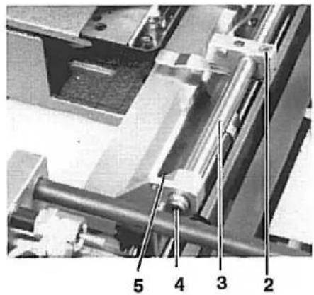
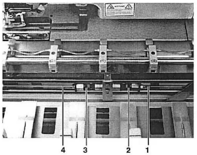
Das Führungsrohr 3 der Klemmstation ist so gestaltet, daß es gleichzeitig zum Herausblasen des Nähgutes in den Stapler genutzt wird. Auf der Unterseite sind dazu in gleichmäßigen Abständen Bohrungen angebracht. Das Ende ist durch einen Stopfen 4 verschlossen.
Die Stoffklemmen sollen bei eingeschalteter Nähanlage einen Abstand von 5 - 6 mm zum Auflageblech haben und mittig zu den Aussparungen 1 der Übergabestation stehen.
Vorsicht Verletzungsgefahr!
Vor dem Einstellen Hauptschalter ausschalten.
Blasrohr prüfen
- Programm 64 anwählen
- S22 anwählen und durch Betätigen des Tasters b132 im Tippbetrieb das Blasen einschalten. Bei eingeschaltetem Blasen die Richtung der ausströmenden Luft kontrollieren.
- Klemmschraube 5 an der linken und rechten Halterung lösen.
- Führungsrohr in den Halteklammern so verdrehen, daß der Luftstrom in den Stapler gerichtet wird.
Blasrohr ausrichten
Stoffklemmen ausrichten
- Druckluft am Druckregler absperren
- Übergabestation einschieben
- Schrauben 2 an den Halteklammern lösen
- Stoffklemmen mittig zu den Aussparungen 1 der Übergabestation stellen.
- In der Höhe einen Abstand von 5-6 mm zum Auflageblech der Klemmstation einstellen.
natural_image
Mechanical assembly with numbered components (5, 6, 7) showing internal components and alignment lines (no readable text or symbols)Die Klemmstation steht zu Beginn jeder Knopflochnaht in ihrer Grundstellung. Diese Grundstellung ergibt sich, wenn der Abstand zwischen Halterung 5 und Kante 7 der Klemmstation 165 mm beträgt.
Während des Nähvorganges ist die Klemmstation mit der Nähstation gekoppelt und führen eine synchrone Bewegung aus.
Nach dem Nähvorgang wird die Klemmstation durch die Kolbenstan-gen 1 und 4 wieder in ihre Grundstellung gedrückt.
Vorsicht Verletzungsgefahr!
Vor dem Einstellen Hauptschalter ausschalten.
- Druckluft am Druckluftregler absperren
- Klemmstation von Hand in ihre Grundstellung schieben und durch geeignete Mittel festsetzen.
- Klemmschrauben 6 an den beiden Mittelstellungszylindern lösen.
- Kolbenstangen 1 und 4 ganz herausziehen und mit ihnen die Dämfer 2 und 3 bis an die Anschlagringe zusammendrücken.
- Linken Kolben (von vorne gesehen) so verstellen, daß der Abstand zwischen Halterung 5 und Kante 7 der Klemmstation 165 mm beträgt.
- Klemmschrauben 6 an den Zylinder festziehen.
natural_image
Mechanical assembly diagram showing a conveyor system with labeled components (no readable text or symbols)
Damit die Klemmstation nicht schlagartig in die Grundstellung geschoben wird, ist der Anschlag 1 für die Grundstellung mit zwei Stoßdämpfern ausgestattet.
In Verbindung mit den Drosseln 2 ermöglichen sie ein weiches Verschieben der Klemmstation in ihre Grundstellung.
Hutmuttern der Stoßdämpfer so einstellen, daß sich eine ausreichende Dämpfung ergibt.
Wird die Dämpfung zu groß gewählt, kann das zur Folge haben, daß die Klemmstation nicht sicher in ihre Grundstellung gedrückt werden kann.
Vorsicht Verletzungsgefahr!
Vor dem Einstellen Hauptschalter ausschalten.
line
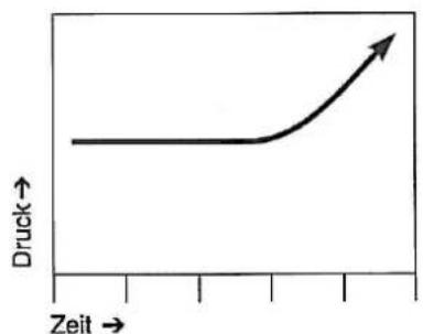
| Zeit | Druck | |------|-------| | 0 | 1 | | 1 | 1 | | 2 | 1 | | 3 | 1 | | 4 | 1 | | 5 | 1 | | 6 | 1 | | 7 | 1 | | 8 | 1 | | 9 | 1 | | 10 | 1 |- Hutmutter des Stoßdämpfers möglichst weit herausdrehen. Die Dämpferwirkung erfolgt erst ziemlich spät. (Siehe Abbildung links)
- Drossel 2 so einstellen, daß die Zylinder zügig aber nicht schlagartig ausfahren. Beide Zylinder sollen möglichst gleichmäßig ausfahren.
Nach Einstellung der Dämpfer bitte die Grundeinstellung der Klemmstation nach Kapitel 2.3.3 überprüfen. Ungleichmäßige Knopflochabstände könnten sich ergeben.
- Schalter 5 für die Mittelstellung so knapp wie möglich schalten lassen. Dazu Schrauben 3 und 4 lösen und Schalter verstellen.
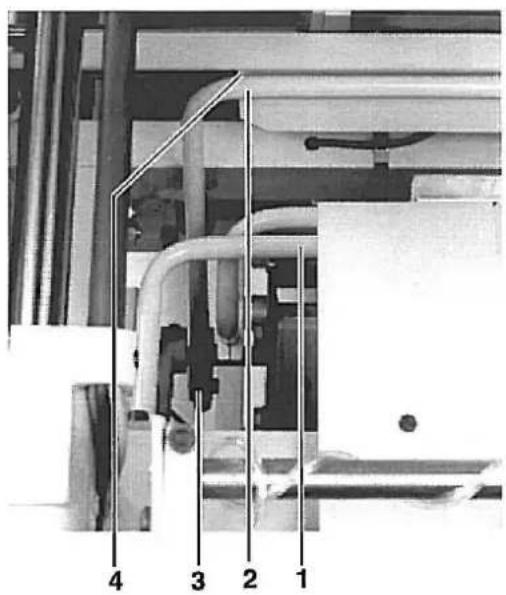
2.4 Übergabestation
2.4.1 Horizontale und vertikale Ausrichtung der Übergabestation
Das Auflageblech 1 der Übergabestation soll über seine ganze Länge in der Höhe den gleichen Abstand zum Auflageblech 2 der Klemmstation haben. Wird die Übergabestation von Hand eingeschoben, soll das Auflageblech 1 ca. 5 mm vor der Kante 3 des Klemmstationauflagebleches aufliegen.
Vorsicht Verletzungsgefahr!
Vor dem Einstellen Hauptschalter ausschalten.
Horizontale Ausrichtung
- Druckluft am Druckregler absperren.
- Schalter 5 entfernen.
- Die Schrauben hinter Schalter 5, Schrauben 4 und 10 lösen.
— Entsprechende Schrauben am rechten Holm lösen. - Mit Schrauben 6 am linken und rechten Holm die erforderliche Höhe des Auflagebleches einstellen.
- Schraube 4 und 5 sowie die Schrauben am rechten Holm festziehen.
- Traverse 9 so neigen, daß sie parallel zur Traverse 8 steht.
- Schraube 10 fest anziehen.
- Übergabestation einschieben und überprüfen, ob das Auflageblech 5 mm vor Kante 3 leicht schabend überwegfährt.
Vertikale Ausrichtung
- Übergabestation von Hand soweit einschieben, das Kante des Bleches 1 der Übergabestation und die Kante des Bleches 3 der Klemmstation zur Deckung gelangen.
– Die vier Befestigungsschrauben 7 am Führungskloben lösen - Übergabestation durch Verdrehen mit Blech 3 in Deckung bringen
- Schrauben 7 mit hohem Drehmoment wieder festziehen.
Der Führungskloben der Übergabestation ist geschlitz und mit speziellen Lagern ausgestattet. Die Lager müssen leichtgängig, aber ohne Luft über das Führungsrohr gleiten.
Vorsicht Verletzungsgefahrl
Vor dem Einstellen Hauptschalter ausschalten.
- Schrauben 4 und 5 lösen.
- Mit den Schrauben 1 und 2 den geschlitzten Teil so einstellen, daß der Kloben leicht aber ohne Luft über das Führungsrohr gleitet.
— Schrauben 4 und 5 wieder anziehen. - Kontermuttern an Schrauben 1 und 2 festziehen.
Gegenschrauben 3 und 5 für die Endschalter
Der Führungsblock besteht aus Aluminium. Da der Schalter 7 nicht auf Aluminium reagiert, muß zum einwandfreien Schalten immer eine Metallschraube vorhanden sein.
Schrauben 3 und 5 nicht entfernen.
Dämpferschraube an der Tiefenspindel
- Dämpferschraube 8 so einstellen, daß der Schlitz der Schraube nach oben zeigt.
Vordere und hintere Endstellung der Übergabestation
Die vordere Endstellung der Übergabestation ist abhängig vom Knopflochabstand zur Stoffkante.
Die Begrenzung erfolgt durch Spindel 6.
In der hinteren Stellung wird der Führungsschlitten bis an den Anschlagring 4 geschoben. Der Dämpfer 5 bremst den Anschlag.
Einstellen der Halteklemmen.
Das Führungsrohr 2 der Übergabestation ist so gestaltet, daß es gleichzeitig als Luftzuführung zum Heben und Senken der Stoffklemmen dient.
Vorsicht Verletzungsgefahr!
Vor dem Einstellen Hauptschalter ausschalten:
- Druckluft am Druckregler absperren.
- Schrauben 1 an den Halteklammern lösen.
- Halteklammern so verstellen, daß die Bohrungen des Führungsrohres 2 und der Halteklammern deckungsgleich stehen.
- Schrauben 3 lösen und die Höhe der Halteklammern zum Auflageblech auf 7 mm einstellen.
2.5 Stoffanschlag einstellen.
natural_image
Mechanical assembly diagram showing a multi-stage linear motor system with labeled components (no readable text or symbols)
Der angehobene Stoffanschlag 1 soll einen Abstand von 1 mm zur zurückgezogenen Übergabestation haben. Die Höhe wird je nach Nähgutstärke mit Hebel 5 verändert.

Vorsicht Verletzungsgefahr!
Hauptschalter ausschalten.
- Übergabestation in ihre Einlege-Stellung schieben.
- Schrauben 3 an der linken und rechten Befestigung lösen.
- Stoffanschlag anheben und einen Abstand von 1 mm parallel zum Auflageblech 2 einstellen.
- Schrauben 3 wieder festziehen.
- Stoffanschlag herunterlassen.
- Schrauben 4 an der linken und rechten Befestigung lösen.
- Stoffanschlag in der Höhe so einstellen, daß das Auflageblech der Übergabestation beim Einfahren ungehindert überweg fahrten kann.
- Schrauben 4 wieder festziehen.
2.6 Stapler
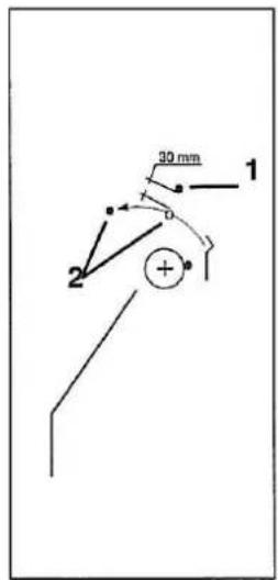
2.6.1 Stellung von Klemmhebel und Klemmrohr zum Stapelgutträger

Wenn Klemmhebel 1 und Klemmrohr 3 am Stapelgutträger 2 anliegen, dan soll zwischen beiden ein Abstand von ca. 20 mm bestehen.

Vorsicht Verletzungsgefahr!
Vor dem Einstellen Hauptschalter ausschalten.
- Druckluft am Druckregler absperren.
- Schrauben 5 links und rechts am Klemmrohr lösen.
- Klemmrohr 3 so einstellen, daß es mittig auf Stapelgutträger 2 steht.
- Schrauben 5 festziehen.
- Schrauben 4 lösen.
- Ein 20 mm breites Metallstück 6 (Zeichnung) zwischen Klemmhebel 1 und Klemmrohr 3 legen.
- Klemmhebel und -rohr zusammenschieben.
- Schrauben 4 festziehen.
natural_image
Mechanical assembly diagram showing a mechanical component with labeled parts 5 and 6 (no readable text or symbols beyond labels)Wenn der Ausstreifer 2 sich unter Klemmhebel 1 herbewegt, dann soll zwischen beiden ein Abstand von ca. 30 mm bestehen.
Vorsicht Verletzungsgefahr!
Vor dem Einstellen Hauptschalter ausschalten.
- Druckluft am Druckregler absperren.
- Schrauben 3 links und rechts am Ausstreifer lösen.
- Ausstreifer so verstellen, das er in der Ruhestellung mittig in der Ausbuchtung 4 liegt.
- Schrauben 3 festziehen.
- Schraube 5 lösen.
- Nocken so auf der Welle verschieben, daß bei herausgeschobenem Zylinder 6 der Klemmhebel 1 einen Abstand von ca. 30 mm zum Ausstreifer hat, wenn beide auf gleicher Höhe liegen. (Zeichnung)
Wenn bei völlig ausgefahrener Kolbenstange 2 der Ausstreifer 1 seinen maximalen Ausschlag erreicht hat, dann soll der Nocken 3 Schalter 5 betätigen und dadurch die Umkehrbewegung des Ausstreifers auslösen.
Vorsicht Verletzungsgefahr!
Vor dem Einstellen Hauptschalter ausschalten.
- Ausstreifer in in die vordere Position ziehen.
- Nocken 3 so verstellen, daß er den Schalter 4 betätigt.
- Ausstreifer in die Grundstellung zurückstellen.
- Nocken 4 so verstellen, daß Schalter 6 beätigt wird.
- Prüfen des Ausstreifers. (Siehe Programmbeschreibung der Steuerung.)

Foreword
This instruction manual is intended to help the user to become familiar with the machine and take advantage of its application possibilities in accordance with the recommendations.
The instruction manual contains important information on how to operate the machine securely, properly and economically. Observation of the instructions eliminates danger, reduces costs for repair and down-times, and increases the reliability and life of the machine.
The instruction manual is intended to complement existing national accident prevention and environment protection regulations.
The instruction manual must always be available at the machine/sewing unit.
The instruction manual must be read and applied by any person that is authorized to work on the machine/sewing unit. This means:
- Operation, including equipping, troubleshooting during the work cycle, removing of fabric waste,
– Service (maintenance, inspection, repair and/or - Transport.
The user also has to assure that only authorized personnel work on the machine.
The user is obliged to check the machine at least once per shift for apparent damages and to immediately report any changes (including the performance in service), which impair the safety.
The user company must ensure that the machine is only operated in perfect working order.
Never remove or disable any safety devices.
If safety devices need to be removed for equipping, repairing or maintaining, the safety devices must be remounted directly after completion of the maintenance and repair work.
Unauthorized modification of the machine rules out liability of the manufacturer for damage resulting from this.
Observe all safety and danger recommendations on the machine/unit! The yellow-and-black striped surfaces designate permanend danger areas, eg danger of squashing, cutting, shearing or collision.
Besides the recommendations in this instruction manual also observe the general safety and accident prevention regulations!
Foreword and general safety instructions
Part 1: Operating and Installation Instructions 741-26/-27
1. Operating Panel
1.1 Operating and Control Elements of the Control Unit 3
1.2 Control Elements on the Sewing Unit/ Maintenance unit 4
2. Setting Up the Sewing Unit
2.1 Transporting the Sewing Unit 5
2.2 Removing the Shipping Fastenings 6
2.3 Mounting the Sewing Head 7
2.4 Mounting the Control Panel, Thread Stand and Synchronizer 8
2.5 General Visual Inspection 9
2.6 Connecting the Sewing Unit Electrically and Pneumatically 9
2.7 Commissioning 10
2. Setting Up the Sewing unit
2.1 Transporting the Sewing Unit
The sewing unit is equipped with 4 transport rollers 2. These transport rollers, however, are only for short distances e.g. within the manufacturing line etc. Longer distances should be covered with a low lift truck.
Lifting the Sewing Unit from the Pallet.
— Push the forklift forks under the brace 3 from the right
- Lift the sewing unit.
Transport the assembled sewing unit
Caution Risk of Injury!
The sewing head can move during transport and thereby shift its weight. The sewing unit can fall off the lift truck.
When the sewing unit is at its work station the transport rollers 2 should be screwed in so far that that sewing unit stands on all four feet 1.
2.2 Removing the Shipping Fastenings
natural_image
Industrial machine with mechanical components and a metal frame (no visible text or symbols)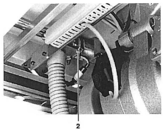
natural_image
Mechanical assembly diagram showing hoses and components with no visible text or symbols
natural_image
Mechanical assembly diagram showing a frame with rollers, brackets, and structural components (no visible text or symbols)
natural_image
Close-up of an electronic device with visible wiring and components, no readable text or symbols present.The sewing unit has four shipping fastenings:
- Securing the sewing head carriage lengthwise through screw 1
- Securing the sewing head carriage crosswise through clip 2
— Securing the transfer station through clip 3
— Securing the clamping station through band clamp 4
Remove all 4 shipping fastenings before making the sewing unit operational.
2.3 Mounting the Sewing Head / Synchronizer
The sewing head is inserted into the already mounted base. The necessary screws are found in the accessories pack.
Caution Risk of Injury!
Insert the sewing head with a crane or two persons. Pinch/crush hazard.
- Insert the sewing head and secure with the two screws 7.
- Lift the sewing head and screw both shock absorbers 1 and 3 tight in the mountings.
- Screw the connection bracket 6 with screw (fastened to the sewing head with a band clamp) to lever 5.
- Establish the electrical and pneumatic connections 2 and 4.
- Lower the sewing head.
- Mount the synchronizer. For setting see Operating Instructions Class 576.
2.4 Mounting the Control Panel, Thread Stand and Synchronizer
natural_image
Industrial machine setup with control panel and labeled components (no readable text or symbols)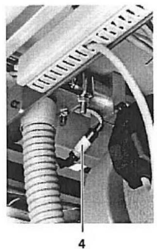
natural_image
Mechanical assembly showing a coiled spring and connecting rod (no visible text or symbols)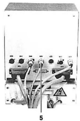
natural_image
Electrical control panel with multiple switches and cables, labeled '5' (no readable text or symbols beyond labels)The control panel connections are equipped with differing plug systems. Wrong connections are therefore impossible.
An indicator lamp is installed in the thread stand duct. It shows e.g. that the spool reserve has run out or, with multiposition systems, if the sewing order has been initiated.
- Mount the control panel 1 and establish the plug connection 5.
- Mount the thread stand 3 and establish the plug connection 4.
- Mount the synchronizer 2. The setting of the positions can be found in the Service Instructions Class 576 page 31.
2.5 General Visual Inspection
Conduct a general visual inspection of the sewing unit.
During transport were:
- Parts broken off,
- Parts obviously misaligned or misadjusted.
2.6 Connecting the Sewing Uunit Electrically and Pneumatically

For special attention!
The mains voltage and the nominal voltage on the motor rating plate must agree.
All work on the electrical components may only be conducted by authorized personnel and with the mains plug pulled.
Please observe the General Safety Notes.
natural_image
Industrial equipment setup with pressure gauges and tubing (no visible text or symbols)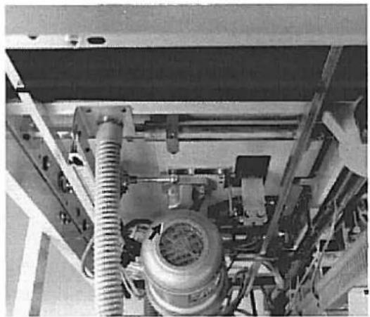
natural_image
Interior view of an industrial machine with hoses and a cylindrical component (no visible text or symbols)- Connect the hose of the sewing unit to the compressed air supply (7-10 bar)
- Connect the sewing unit plug to the mains.
- Take note that operation is only allowable with the voltage shown on the rating plate.
- Set the operating pressure of 6 bar at pressure regulator 2 and 4 bar at pressure regulator 1.
- Turn on the sewing unit and check the direction of otor rotation. (See photo). If the motor runs in the wrong direction 2 phases on the mains plug should be interchanged.
2.7 Commissioning
natural_image
Industrial machine setup with labeled components (1, 2), no visible text or symbols on the machinery itself.Trial Run
First conduct a trial run without material in order to check the correct setting of the synchronizer.
- Set switch b111 to 9. Thread monitor is switched off.
- Set switch b109/110 to 01. One buttonhole is sewn.
- Set switch b105/106/107 to 30. Minimum buttonhole interval.
- Start the sewing unit.
- Check the stop position of the sewing head and, if necessary, correct the synchronizer. See Service Instructions Class 576 page 31.
Positioning Markings left and right
Example:
The first buttonhole is to have the shortest to be sewn clearance e.g. 5 cm to the upper material edge.
- Run the sewing head to the left starting position.
- Place the material so that there is a clearance of about 5 cm from the upper material edge to the needle.
- Attach marking 2 to the material rest of the transfer station.
- Turn on the sewing unit.
- Conduct the sewing sequence.
- On the finished piece check the interval and correct marking 2, if necessary.
- Attach the right marking 1 as described above.
A displacement of the first buttonhole can be made with switch b1:23/124.
Part 2: Service Instructions 741-26/27
- General 3
1.1 Removing the Trim Panels and Bellows 3
- Setting the Advancing Device
2.1 Forward and Rear End Position of the Sewing Head 4
2.2 Left and Right End Position of the Sewing Head 5
2.3 Clamping Station
2.3.1 Horizontal and Vertical Alignment of the Clamping Station/ Clearance to the Sewing Head . . 6
2.3.2 Aligning the Blower Pipe and Material Clamps 7
2.3.3 Base Position of the Clamping Station 8
2.3.4 Absorbers and Switches for the Base Position 9
2.4 Transfer Station
2.4.1 Horizontal and Vertical Alignment of the Transfer Station 10
2.4.2 Guide Block of the Transfer Station 11
2.4.3 Forward and Rear End Positions of the Transfer Station/ Aligning the Material Clamps ..... 12
2.5 Setting the Material Stopper 13
2.6 Stacker
2.6.1 Setting the Clamping Lever and Clamping Pipe to the Stacked Goods Holder ..... 14
2.6.2 Setting the Clamping Lever to the Remover 15
2.6.3 Remover Movement 16
1. General

ATTENTION!
The tasks described in the Service Instructions may only be carried out by skilled personnel or appropriately trained persons!
Caution Risk of Injury!
By repair, conversion and maintenance work turn off the main switch and disconnect the machine from the pneumatic supply lines. Conduct adjustment work and function testing on an operational machine only with the greatest care and observing all safety measures.
These service instructions describe in a practical order the setting of the advancing device.
Here care should be taken since various setting positions are interdependent. Therefore it is essential setting be conducted keeping to the order described.
1.1 Removing the Trim Panels and Bellows
natural_image
Industrial machine setup with control panel and conveyor system (no visible text or symbols)Remove for service purposes:
- the side and rear trim panels
- the cover plates 1 and 2
- the bellows.
2. Setting the Advancing Device
2.1 Forward and Rear End Positions of the Sewing Head
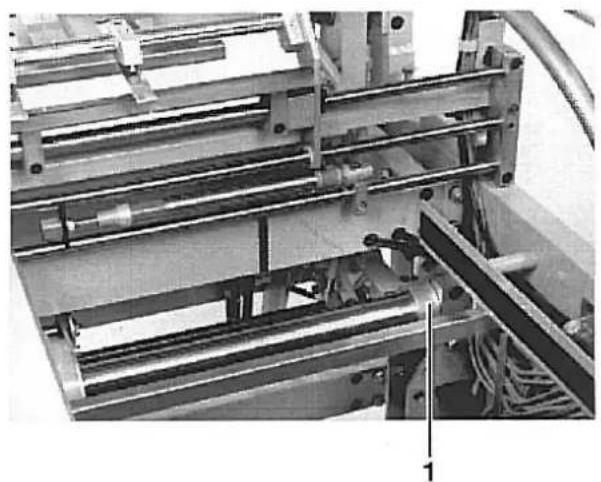
The cylinder 9 pushes the sewing head into the positions (A) and (B). Position (A) is taken for sewing, position (B) for service work on the sewing head.
In position (A) the feed plate 1 of the clamping station should have a clearance of 1 mm to the rear edge 4 of the plate 3.
In position B the feed plate should have a clearance of 5 mm to the material carrier plate 2 of the sewing head.
Caution Risk of Injury!
Before adjusting turn off main switch.
- Loosen limiter blocks 6, 7, 8 and 9.
— Push the sewing head back to about 1 mm from the feed plate 1. - Set the limiter blocks 6 and 7 on the support pipe and screw-tight:
- Set the screw 5 on the limiter switch with a bit of a gap
- Push the sewing head 5 mm to the back until the sewing head can be tilted up without hindrance.
- Set the limiter blocks 8 and 9 onto the support pipe and screw tight.
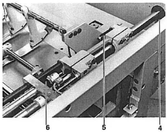
2.2 Left and Right End Positions of the Sewing Head
natural_image
Industrial machine with mechanical components and wiring (no visible text or symbols)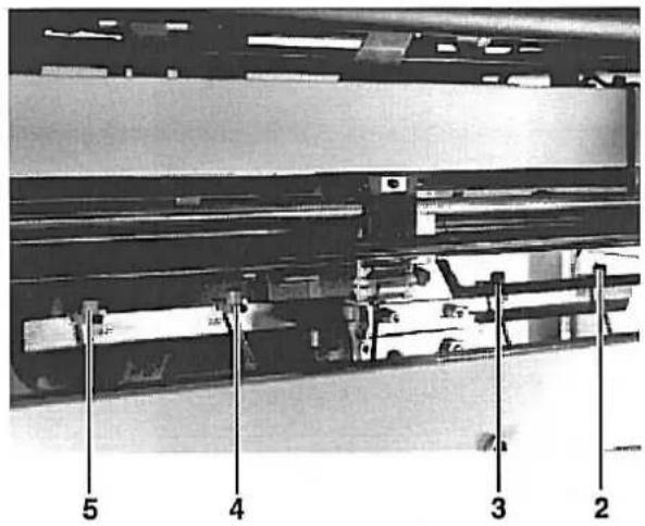
In order to use the full sewing length of the unit the sewing head carriage must run as close as possible onto the left and right stop ring 1.
Caution Risk of Injury!
Do not reach into the movement area of the sewing head.
- Select testing program P58
- Push switches 3 (b18) and 4 (b20) somewhat closer together
- Run the sewing head into the right or left end position.
- Gradually slide the switches 3 (b18) and 4 (b20) to the outside until the carriage runs lightly onto the stop ring 1 in each end position.
- Set the distance between switches 4 and 5 as well as 2 and 3 at 110 mm. (measured center/center)
2.3 Clamping Station
2.3.1 Horizontal and Vertical Alignment of the Clamping Station/ Clearance to the Sewing Head
Horizontal Alignment:
The feed plate 1 of the clamping station must lie parallel to and a bit higher than the material carrier plate 2 along its whole length.
Vertical Alignment:
If the sewing head is in the sewing position there should be a clearance of 1 mm between the feed plate 1 and the edge 3 of the needle plate along the whole length.

Caution Risk of Injury!
Before adjusting turn off main switch.
Horizontal Alignment:
- Loosen screws 5 and 6 on the left and right mounting angles.
- Slide the clamp in the slots so that there is an equidistant gap between the material carrier plate 2 and the feed plate 1 along the full length.
- Tighten screws 5 and 6 again.
- Push the sewing head into the right and left end positions and check the gap along the whole length.
Vertical Alignment:
- Loosen screws 4 on the left and right mounting angles.
- Slide the angles so that the feed plate 1 has a clearance of 1 mm to the edge 3 of the needle plate.
- Push the sewing head into the right and left end positions and check the clearance along the full length.
natural_image
Industrial machine with metal brackets and a DORKOPP AG label, no readable text or symbols beyond branding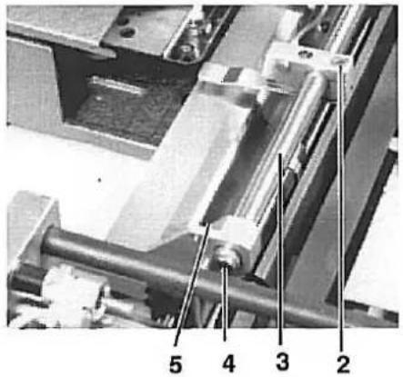
The design of the guide pipe 3 of the clamping station is such that it is used for blowing out the material in the stacker at the same time. For this there are holes at regular intervals on the underside. The end is closed with a plug 4.
With the sewing unit switched on the material clamps should have a clearance of 5 - 6 mm to the feed plate and lie centered to the recesses 1 of the transfer station.
Caution Risk of Injury!
Before adjusting turn off main switch.
Checking the Blower Pipe
- Select program 64
- Select S22 and tap key b132 to turn on the blower. With the blowerbturned on check the direction of the air flow.
Aligning the Blower Pipe
- Loosen attachment screw 5 on the left and right mountings.
- Turn the guide pipe in the holding clamps so that the air flow is directed into the stacker.
Aligning the Material Clamps
- Cut off the compressed air at the pressure regulator
- Insert the transfer station
- Loosen screws 2 on the holding clamps
- Set the material clamps centered to the recesses 1 on the transfer station.
- Set a height clearance of 5-6 mm to the feed plate of the clamping station.
natural_image
Mechanical assembly diagram showing layered components and labeled parts (no readable text or symbols)The clamping station is in its base position at the start of each buttonhole seam. This base position results when the clearance between the mounting 5 and edge 7 of the clamping station is 165 mm.
During the sewing procedure the clamping station is coupled with the sewing station and they conduct a synchronized movement.
After the sewing procedure the clamping station is pressed into its base position again by the piston rods 1 and 4.
Caution Risk of Injury!
Before adjusting turn off main switch.
- Shut off the compressed air at the pressure regulator
- Push the clamping station into its base position by hand and set fast.
- Loosen the clamping screws 6 on both central positioning cylinders.
— Pull the piston rods 1 and 4 completely out and press the absorbers 2 and 3 together with them up to the stop rings. - Adjust the left piston (seen from the front) so that the clearance between the mounting 5 and the edge 7 of the clamping station is 165 mm.
— Tighten the clamping screws 6 on the cylinders.

natural_image
Mechanical assembly diagram showing a multi-stage assembly with labeled components (no readable text or symbols)
In order that the clamping station not be pushed into the base position with a jerk, the stopper 1 for the base position is equipped with two shock absorbers.
In conjunction with the throttles 2 they make a smooth slide of the clamping station into its base position possible.
Set the cap nuts of the shock absorbers so that sufficient dampening results.
If the dampening is too great this can result in the clamping station cannot be securely pushed into its base position.
Caution Risk of Injury!
Before adjusting turn off main switch.
line
| Zeit | Druck | |------|-------| | 0 | ↑ | | >1 | → |- Screw the cap nut of the shock absorber out as far as possible. The dampening effect does not occur until relatively late. (See illustration left)
- Set throttle 2 so that the cylinders run out quickly but not with a jerk. Both cylinders should run out as evenly as possible.
After setting the absorbers check the base position of the clamping station as per chapter 2.3.3. Unequal buttonhole intervals could result. - Let switch 5 for the central position switch as narrowly as possible. To this loosen screws 3 and 4 and adjust the switch.
2.4 Transfer Station
2.4.1 Horizontal and Vertical Alignment of the Transfer Station
The feed plate 1 of the transfer station should have the same height clearance to the feed plate 2 of the clamping station along its full length. If the transfer station is inserted by hand, the feed plate 1 should lay on about 5 mm in front of the edge 3 of the clamping station feed plate.
Caution Risk of Injury!
Before adjusting turn off main switch.
Horizontal Alignment
- Shut off the compressed air at the pressure regulator.
- Remove switch 5.
- Loosen the screws behind switch 5, screws 4 and 10.
- Loosen the corresponding screws on the right spar.
- with screws 6 on the left and right spars set the required height of the feed plate.
- Tighten screws 4 and 5 as well as the screws on the right spar.
- Tilt traverse 9 so that it is parallel to traverse 8.
- Tighten screw 10.
- Insert the transfer station and check that the feed plate runs above, slightly scraping, 5 mm in front of edge 3.
Vertical Alignment
- Insert the transfer station so far by hand that the edge of the plate 1 of the transfer station and the edge of the plate 3 of the clamping station overlap.
- Loosen the four mounting screws 7 on the guide block
- Make the transfer station overlap with plate 3 by twisting
- Retighten the screws 7 with high torque.
2.4.2 Guide Blocks of the Transfer Station
The guide block of the transfer station is slotted and equipped with special bearings. The bearings must be easy to move but run on the guide pipe without a gap.
Caution Risk of Injury!
Before adjusting turn off main switch.
- Loosen screws 4 and 5.
- Set the slotted part with screws 1 and 2 so that the block slides easily over the guide pipe but without a gap.
- Retighten screws 4 and 5.
- Tighten the lock nuts on screws 1 and 2.
Counter Screws 3 and 5 for the Limiter Switch
The guide block is of aluminium. Since the switch 7 does not react to aluminium a metal screw must always be present for faultless switching.
Do not remove screws 3 and 5.
Dampening Screw on the Height Spindle
- Set the dampening screw 8 so that the slot of the screw is turned to the top.
natural_image
Mechanical assembly diagram showing components labeled 4, 5, and 6 (no readable text or symbols beyond labels)Forward and Rear End Positions of the Transfer Station
The forward end position of the transfer station is dependent on the buttonhole clearance to the material edge.
Limiting occurs via spindle 6.
In the rear position the guide carriage is pushed onto the stop ring 4. The absorber 5 brakes the stop.
Setting the Holding Clamps.
The guide pipe 2 of the transfer station is so designed that it simultaneously serves as an air feed for raising and lowering the material clamps.
Caution Risk of Injury!
Before adjusting turn off main switch.
- Shut off compressed air at the pressure regulator.
- Loosen the screws 1 on the holding clamps.
- Set the holding clamps so that the holes on the guide pipe 2 and the holding clamps are congruent.
- Loosen screws 3 and set the height of the holding clamps to the feed plate at 7 mm.
2.5 Setting the Material Stopper.

natural_image
Mechanical assembly diagram showing a linear motor with labeled parts (1 and 2), no readable text or symbols beyond labels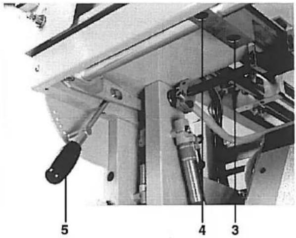
The raised material stopper 1 should have a clearance of 1 mm to the pulled back transfer station. The height is adjusted with lever 5 depending on the material thickness.
Caution Risk of Injury!
Turn off main switch.
- Push the transfer station into its feed position.
- Loosen screws 3 on the left and right mountings.
- Lift the material stopper and set a clearance of 1 mm parallel to the feed plate 2.
- Tighten screws 3 again.
- Lower the material stopper.
- Loosen screws 4 on the left and right mountings.
- Set the height of the material stopper so that the feed plate of the transfer station can move unhindered above it when being run in.
- Tighten screws 4 again.
2.6 Stacker
2.6.1 Setting of the Clamping Lever and Clamping Pipe to the Stacked Goods Holder
When the clamping lever 1 and clamping pipe 3 lay onto the stacked goods holder 2 there should be a clearance of about 20 mm between the two.
Caution Risk of Injury!
Before adjusting turn off main switch.
- Shut off compressed air at the pressure regulator.
- Loosen screws 5 left and right on the clamping pipe.
- Set the clamping pipe 3 so that it lies centered on the stacked goods holder 2.
- Tighten screws 5.
- Loosen screws 4.
- Place a 20 mm wide metal piece 6 (Drawing) between clamping lever 1 and clamping pipe 3.
- Push clamping lever and pipe together.
- Tighten screws 4.

natural_image
Mechanical assembly diagram showing a mechanical component with labeled parts 5 and 6 (no readable text or symbols beyond labels)When the remover 2 moves under the clamping lever 1 there should be a clearance of about 30 mm between them.
Caution Risk of Injury!
Before adjusting turn off main switch.
- Shut off compressed air at the pressure regulator.
- Loosen screws 3 left and right on the remover.
- Set the remover so that it lies centered in the recess 4 when at rest.
- Tighten screws 3.
- Loosen screw 5.
- Slide the cams on the shaft so that with extended cylinder 6 the clamping lever 1 has a clearance of about 30mm to the remover when both are at the same height. (Drawing)
When, with fully run-out piston rod 2, the remover 1 has reached its maximum extension then the cam 3 should operate switch 5 and thereby activate the return movement of the remover.

Caution Risk of Injury!
Before adjusting turn off main switch.
— Pull the remover into the forward position.
- Set the cam 3 so that it operates switch 4.
- Place the remover back in the base position.
- Set the cam 4 so that switch 6 is operated.
- Check of the remover.
(See Control Program Description.)