1/5 EX 200A ESC - Fjernstyret legetøj SkyRC - Gratis brugsanvisning og manual
Find enhedens vejledning gratis 1/5 EX 200A ESC SkyRC i PDF-format.

Brugerspørgsmål om 1/5 EX 200A ESC SkyRC
0 spørgsmål om dette apparat. Besvar dem du kender, eller stil dit eget.
Stil et nyt spørgsmål om dette apparat
Download vejledningen til din Fjernstyret legetøj i PDF-format gratis! Find din vejledning 1/5 EX 200A ESC - SkyRC og tag din elektroniske enhed tilbage i hånden. På denne side er alle dokumenter nødvendige for brugen af din enhed offentliggjort. 1/5 EX 200A ESC af mærket SkyRC.
BRUGSANVISNING 1/5 EX 200A ESC SkyRC
INSTRUCTION MANUAL
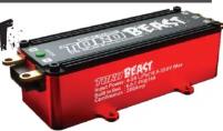
BUILT IN BEC TORO BEAST US SCALE BRUSHLESS ESC 200A
INTRODUCTION
Thank you for purchasing TORO BEAST 1/5 200A ESC from SKYRC TECHNOLOGY CO.,LTD. Please read the Instruction Manual thoroughly before you use the product. These operating instructions are designed to ensure that you quickly become familiar with its features and functions and make full use of this product.
FEATURES
● Built-in high power BEC. Output voltage is selectable between 6.0V and 7.4V. Maximum output current is up to 15A
• Support LiPo batteries up to 8S.
- Data Logging: The controller can measure and record parameters such as your battery volts, amp draw, motor rpm, and controller temperature. This is a great way to make sure that the rest of your setup is performing within its limits.
- Red copper connector is used internally of the ESC. It can decrease the internal resistance at high current situation.
- Heat transfer: The internal resistance can be reduced by laminated copper stack control technology so that the dynamic thermal equilibrium can be got. In this case, the metal heat sinks can works effectively.
- Safety features: low voltage protection, motor and ESC overheat protection and signal lost protection.
- It can be programmed by Program Box(SK-300046), PC via SKYLINK(SK-600013) or smart phone via Wi-Fi Module(SK-600075).
The firmware can be updated by connecting the ESC with PC or smart phone.
SAFETY NOTE
- It is not a toy and suitable for users older than 14 years old.
- Never allow water, moisture, oil or other foreign materials to get inside ESC, motor, or on the PC Boards. It may damage the ESC completely.
- Never disassemble the ESC and modify the components on the PC Boards.
- Suggest using the original wires and connectors which are packed in the box.
- Never solder one part for more than 5 seconds as some components will get damaged by high temperature.
- Never run the ESC w/o load at full throttle and it may damage the bearings and other moving parts.
- Please make sure the location where to fix the ESC has good airflow ventilating so that the heat could dissipate quickly.
- The heat could dissipate quickly
- To avoid short circuit, please keep the ESC connectors far away from other metal parts.
- Never connect the battery in polarity in reverse.
- Please remove the pinion gear before performing calibration and programming functions with this system. Please keep your hands, hair, cloth, clear from the gear train and wheels of an armed high performance
- Before you switch on the ESC, please make sure all the cables are well soldered with the connectors (It is easy to get loose when running). What's more, make sure the cables not touch the moving parts.
- Electronic motor timing will increase the temperatures of ESC and brushless motor. Use extreme caution when setting up and testing your application to avoid overloading and overheating.
- To avoid signal interference, please always turn on the transmitter first THEN turn on the speed control. Do the opposite when powering it off
- Never use faulty accessories, e.g. motor which may damage the ESC. Always insulate exposed wiring with heat shrink tubing or electrical tape to prevent short circuits, which can damage ESC too.
- Always disconnect the battery pack from the speed control when not in use to avoid short circuits and possible fire hazard. When the ESC is switched off, there is still small current and it may cause over discharge of the battery after some time.
• The ESC can support 6-8 cells LiPo battery.
Note: We will not be responsible for any damage caused by non-compliance with above instruction.
PREPARATION
1) Plan Speed Control Placement
Choose a location for the speed control that is protected from debris. To prevent radio interference, place the speed control as far away from the radio receiver as possible and keep the power wires as short as possible. Select a location that has good airflow
ventilating. If the ESC gets air flow, it will run cooler; and that means it will be more efficient.
Mount Speed Control in Vehicle
[Non-Text]
Note: You could also refer to Instruction Manual for TORO Conversion Kit Hardware(SK-600003) for more information to fix the ESC.
Cut the ESC's BLUE, YELLOW & ORANGE silicone motor power wires to the desired length and strip about 3.2mm-6.35mm (1/8"-1/4") of insulation from the end of each wire.
*Pre-tin"the wire by heating the end and applying solder until it is thoroughly covered.
CAUTION: By very careful not to splash yourself with hot solder.
Place the ESC's BLUE Phase 'A' motor wire onto motor's 'A' solder tab and solder. Use soldering iron to apply heat to exposed wire; begin adding solder to tip of soldering iron and wire. Add just enough solder to form a clean and continuous joint from the plated area of the solder tab up onto the wire. Solder the ESC's YELLOW Phase 'B' motor wire to the motor's 'B' solder tab and Solder the ESC's ORANGE Phase 'C' motor wire to motor's 'C' solder tab.
Soldering
For a brushless non-sensor system, there is no polarity on the motor side of the controller. Simply solder the three wires to your motor. If the car runs backwards with forward throttle, simply swap any two of the motor wires and it will reverse the direction of the car.
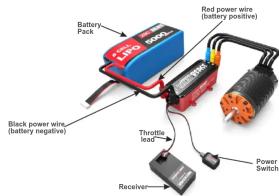
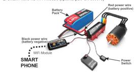
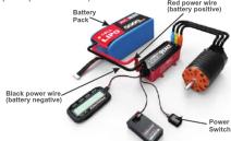
CONNECTION
1) Connect Throttle lead to ESC and other end to the Receiver (Throttle Channel, Ch2) 2) Solder the motor and the ESC. 3) Connect ESC to battery pack.
ESC CALIBRATION
Calibration is necessary for the first use of the ESC, or whenever used with a new/different transmitter. Individual transmitter's signals for full throttle, full brake and neutral vary. You must calibrate your ESC so that it will operate more effectively with your transmitter.
How to calibrate the ESC?
- ESC switch OFF
- Connect the ESC to the battery and the motor.
- Turn on the transmitter.
- Press and hold the ESC switch for few seconds, the motor will ring long beep once. After that, the red LED will blink the motor will ring like beep-beep-beep... in a row which indicates it is time to set the neutral position, full throttle and full brake one by one. You could release the ESC switch now.
- Keep the throttle trigger in neutral position, press the ESC switch once, the green LED will blink once then extinguish and the motor will ring beep once which indicates the neutral position has been set.
- Hold full throttle and press the ESC switch once, the green LED will blink twice then extinguish and the motor will ring twice like beep-beep which indicates the full throttle has been set.
- Move the throttle trigger to full brake and hold full brake, press the ESC switch once, the green LED will blink three times then extinguish and the motor will ring three times like beep-beep-beep which indicates the full bra has been set.
- After the calibration is finished, keep the throttle in neutral position, the red LED is blinking, the ESC and the motor is ready to work.
4/83/82/81/8
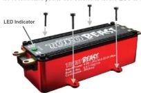
ESC ON/OFF AND LED INDICATOR
- ESC ON/OFF: When the ESC is OFF, press the switch once, the motor will ring beep once and the red LED will blink, then the ESC is ready to work. When the ESC is on, press the switch once, the LED will extinguish and the ESC is OFF or push the throttle trigger to the maximum brake, hold for 8 seconds and the ESC is OFF.
| Note 1: After running at full load, the ESC will be very hot. |
| Note 2: When the motor is running, the ESC can't be powered off by pressing the switch; when the motor stops working, the ESC can be powered off. In an emergency, please disconnect the battery to power off the ESC. |
- Explanation of LED Indicator
| The throttle trigger is in neutral position | Red LED is blinking |
| The motor is running while the throttle trigger doesn't reach to the highest throttle/brake position | Green LED is blinking |
| The throttle trigger is at the highest throttle/brake position. | Green LED stays ON |
ESC PROGRAMMING
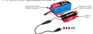
The ESC can be programmed by program box, PC (connected with SKYLINK) or smart phone via Wi-Fi module.
1. PC via SKYLINK (optional part SK-600013)
2. Smart Phone via Wi-Fi Module (optional part SK-600075)
- Program Box (optional part SK-300046)
Programmable Items and Description
| Section | Program Item | Description | |||
| General Setting | Running Mode | Forward/Brake | Forward/Brake/Reverse | Forward/Reverse | |
| Motor Direction | Normal | Reverse | |||
| Reverse Speed | 25-100% (in 1% increment) | ||||
| Voltage Cutoff® | 9.6-42V (in 0.1V increment) | ||||
| BEC Voltage | 6V 7.4V | ||||
| ESC Overheat Protection | 85^ /185^ | 105^ /221^ | 125^ L^ /257^ | Disable | |
| Throttle Control | Punch Rate Switch Point | 1-99%(in 1% increment) | |||
| 1st Stage Punch Rate | 1-30 | ||||
| 2nd Stage Punch Rate | 1-30 | ||||
| TH Input Curve | Line | Custom | |||
| Throttle Dead Band | 10-150us | ||||
| Throttle Status | |||||
| Brake Control | Drag Brake | 0-100%(in 1% increment) | |||
| Brake Strength | 0-100% | ||||
| Initial Brake | —Drag Brake | 0-50% | |||
| Brake Rate Switch Point | 1-99%(in 1% increment) | ||||
| 1st Stage Brake Rate | 1-20 | ||||
| 2nd Stage Brake Rate | 1-20 | ||||
| Brake Input Curve | Line | Custom | |||
| Data Storage | Mode | Single | Cycle | |||
| Start and Stop Control | Start storage once entering in main program | Press control storage entering in main program | ||||
| Choose data types to save | Voltage | Current | Throttle | Current RPM | ESC Temperature | |
| Data Saving Time increment | 0.1S-10S | |||||
* If you set the cut-off voltage manually, please note the adjustable voltage is TOTAL cut-off voltage of the battery pack.
Profiles Preset
The users could preset and store 10 sets of profiles in the ESC. These data could be called out for application at any time without any special program setting. The user could also reset the profile according to his request.
Profile One Setting Value (Default Value)
| Section | Program Item | Description |
| General Setting | Running Mode | Forward/Brake |
| Motor Direction | Normal | |
| Reverse Speed | 25% | |
| Voltage Cutoff | 25.6V | |
| BEC Voltage | 6V | |
| ESC Overheat Protection | 105°C/221°F | |
| Throttle Control | Punch Rate Switch Point | 50% |
| 1st Stage Punch Rate | 5 | |
| 2nd Stage Punch Rate | 5 | |
| TH Input Curve | Line | |
| Throttle Dead Band | 0.080ms | |
| Throttle Status | ||
| Brake Control | Drag Brake | 10% |
| Brake Strength | 75% | |
| Initial Brake | =Drag Brake | |
| Brake Rate Switch Point | 50% | |
| 1st Stage Brake Rate | 10 | |
| 2nd Stage Brake Rate | 16 | |
| Brake Input Curve | Line |
7/86/85/8
SPECIFICATION
| Constant/Burst Current | 200A/800A |
| Motor Compatible | Brushless Sensorless ESC |
| Car Compatible | 1/5 Off Road, On Road |
| Motor Limits | KV ≤ 1100 , 4 Poles |
| Resistance | 0.0002ohm |
| Battery Cell Count | 4-8S LiPo |
| BEC Output | 6.0V/7.4V @ 15A |
| Size | 111x44x37mm (LxWxH) |
| Weight | 359g (without wire) |
WARRANTY AND SERVICE
THE TORO BEAST 1/5 200A ESC is guaranteed to be free from defects in materials or workmanship for a period of 90 DAYS from the original date of purchase (verified by dated, itemized sales receipt). Warranty does not cover incorrect installation, components worn by use, damage to case or exposed circuit boards, cross-connection of battery/motor power wiring and solid solder holes. Voltage application improves performance in commercial FEC, damage resulting from the first headhead or other recruiting motor, damage from incorrect installation of FET servo or receiver battery pack, tampering with internal electronics, allowing water, moisture, or any other foreign material to enter ESC or get onto the PC board, incorrect installation/wiring of input plug plastic, allowing exposed wiring or solder tabs to short-circuit, or any damage caused by a crash, flooding or natural disaster. The device has been used to operate its own circuit board and/or other related electronics, no liability may be assumed nor will be accepted for any damage resulting from the use of this product. Every SKYRC speed control & motor is thoroughly tested & cycled before leaving our facility and is, therefore, considered operational. By the act of connecting/operating speed control, user accepts all resulting liability. In no case shall our liability exceed the products original cost. We reserve the right to modify warranty for the use of this product. For example, if you have a good price of about one of the products of age without the strict supervision of an adult. Use of this product in an uncontrolled manner may result in physical damage or injuries take extra care when operating any remote control.
For any repair or replace service, please contact your dealer in the first instance, who is responsible for processing guarantee claims.


Manufactured by
SKYRC TECHNOLOGY CO., LTD. www.skyrc.com
www.skyfc.com
, Ltd. All Rights Reserved.
8/8