
CQ-FX75 - Bilradio PANASONIC - Gratis brugsanvisning og manual
Find enhedens vejledning gratis CQ-FX75 PANASONIC i PDF-format.


Brugerspørgsmål om CQ-FX75 PANASONIC
0 spørgsmål om dette apparat. Besvar dem du kender, eller stil dit eget.
Stil et nyt spørgsmål om dette apparat
Download vejledningen til din Bilradio i PDF-format gratis! Find din vejledning CQ-FX75 - PANASONIC og tag din elektroniske enhed tilbage i hånden. På denne side er alle dokumenter nødvendige for brugen af din enhed offentliggjort. CQ-FX75 af mærket PANASONIC.
BRUGSANVISNING CQ-FX75 PANASONIC
Operating Instructions 操作說明書
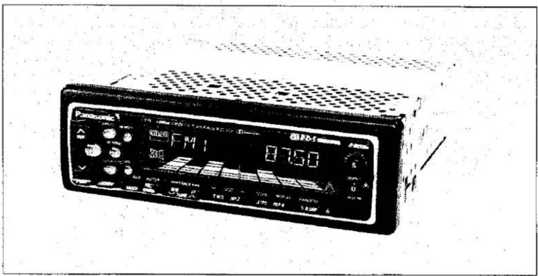
Full-Flap Face High-Power Cassette Player/RDS Receiver 全活門式高功率卡式磁帶放音機/收音機資料系統接收機
CQ-FX75EW
Panasonic®
松下电器
Before operating this set, please read these instructions completely. 操作本裝置之前,請熟讀這些說明。
Contents
Page
Precautions (ISO connector) 3
Precautions 5
Power and Sound Controls 6
Radio Basics 10
RDS (Radio Data System) Reception 13
Cassette Tape Player Basics 21
CD Changer Basics 24
Remote Control Basics 27
Page
Anti-Theft System 28
Installation 31
Electrical Connection 34
Speaker Connections 35
Fuse 36
Maintenance 36
Specifications 36
目錄
頁
注意事項 (ISO連接器) 4
注意事項 5
電源與音量控制 37
收音機基本操作 41
RDS(收音機資料系統)的收聽 44
卡式磁帶放音機基本操作 52
鐳射唱片換片器的基本操作 55
遥控器的基本操作 58
頁
防盜系統 59
安装 62
電器連接 65
揚聲器連接 66
保險絲 67
維修 67
規格 67
Precautions (ISO connector)
- Wiring for the power connector conforms to the arrangement of standard ISO connectors.
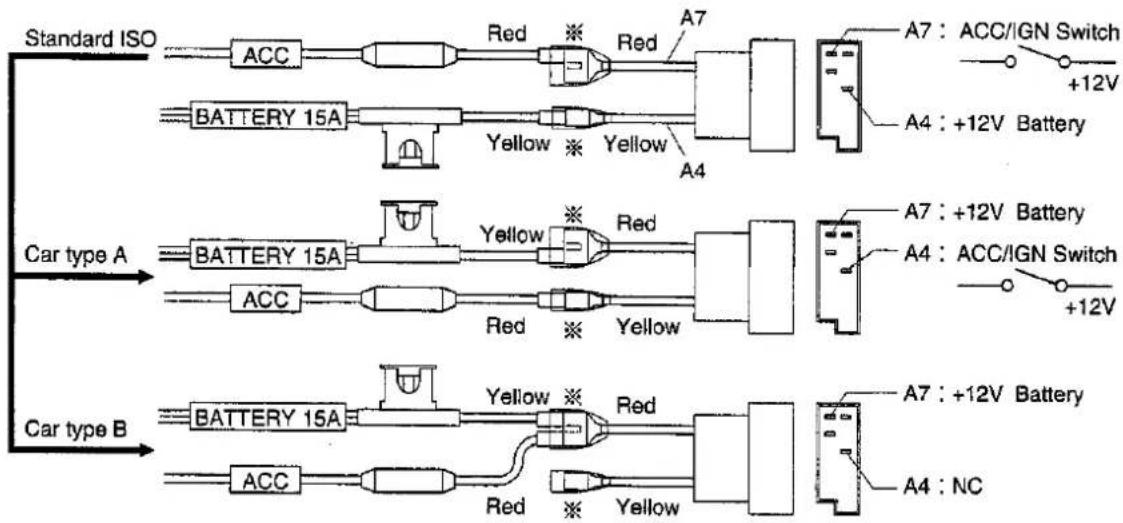
- In case of some car types, the arrangement of connector may differ from the standard ISO as shown in Table 1, even though ISO connectors are adopted.
Table 1
| Fig.1 Pin No. | A4 | A7 |
| Car for standard ISO | Battery(permanent 12 V supply) | "IGN" or "ACC"(switched 12 V supply) |
| In case of Car type A | "IGN" or "ACC"(switched 12 V supply) | Battery(permanent 12 V supply) |
| In case of Car type B | No Connection | Battery(permanent 12 V supply) |
• Make sure the ISO connector arrangement in your car side is as same as the standard ISO.
- In case of arrangement for Car type A or B, change connections of the red/yellow leads at the reconnectable joint (※) as shown in Fig. 1.
Fig. 1
flowchart
graph TD
    A["Standard ISO"] --> B["ACC"]
    B --> C["Red"]
    C --> D["A7"]
    D --> E["A7: ACC/IGN Switch"]
    E --> F["+12V"]
    A --> G["BATTERY 15A"]
    G --> H["Yellow"]
    H --> I["A4"]
    I --> J["A4: +12V Battery"]
    J --> K["A4: ACC/IGN Switch"]
    K --> L["+12V"]

    M["Car type A"] --> N["BATTERY 15A"]
    N --> O["Yellow"]
    O --> P["A7"]
    P --> Q["A7: +12V Battery"]
    Q --> R["A4"]
    R --> S["A4: ACC/IGN Switch"]
    S --> T["+12V"]

    U["Car type B"] --> V["BATTERY 15A"]
    V --> W["Yellow"]
    W --> X["A7"]
    X --> Y["A7: +12V Battery"]
    Y --> Z["A4: NC"]
    U --> AA["ACC"]
    AA --> AB["Red"]
    AB --> AC["A7"]
    AC --> AD["A4: NC"]
- After fix the connections, the part (※) should be insulated with electrical tape to keep away from unit damage.
Panasonic welcomes you to their constantly growing family of electronic products owners.
We endeavor to give you the advantages of precise electronic and mechanical engineering, manufactured with carefully selected components, and assembled by people who are proud of the reputation their work has built for our company. We know this product will bring you many hours of enjoyment, and after you discover the quality, value and reliability we have built into it, you too will be proud to be a member of our family.
Precautions
Volume Level
For your driving safety, keep the volume level low enough to be aware of road and traffic conditions.
Car Washing
To avoid electrical shorts which may cause fire, or other damage, do not expose this equipment (including the speakers and tape) to water or excessive moisture.
Car Ventilation
If your car is parked for several hours in direct sunlight, the temperature inside the car may become very high. It is advisable to drive the car and give the interior a chance to cool down before switching the unit on.
Power Supply
This equipment is designed to be used in a car having 12-Volt negative ground battery system.
Tape Mechanism
Keep magnets, screwdrivers and other metallic objects away from the tape mechanism and tape head.
Service
This unit is made of precision parts. Do not attempt to disassemble or adjust any parts. For repair, please consult your nearest authorized Panasonic Service Center.
About Preset Memory
The preset memory is cleared to return to the original factory setting when the power connector or battery is disconnected.
Panasonic 歡迎您來到不斷增加的電子產品擁有者的家族之中。我們力圖為您提供精密的電子與機械工程的方便性,使用經過認真選擇的零件進行生產,並由對他們的工作已為我公司樹立信譽而感到自豪的人們進行組裝。我們知道這個產品將為您帶來更多享受的時光,當您發現我們的產品所擁有的質量、價值和可靠性之後,您會為自己成為我們家族的一員而感到自豪。
注意事項
音量
為了安全駕駛,請盡量保持低音量,以便注意交通和路面狀況。
洗車時
為了避免電氣短路而引起火災或其它危害,請勿使本設備(包括揚聲器與磁帶)沾水或受潮。
汽車通風
如果您的汽車在直射陽光下停車幾個小時之後,汽車內的溫度會升很高。
在打開本機之前,最好開動汽車,降低車內溫度。
供電
本設備的設計是用於備有12伏負極接地電池系統的汽車中。
磁帶機構
切勿將磁鐵,螺絲刀和其它金屬物靠近磁帶機構和磁頭。
維修
本機由精密部件組成。請勿自行嘗試拆卸或調節任何部件。如要維修,請到您附近的公認的Panasonic維修中心進行詢問。
關於預置記憶
當斷開電源連接器或電瓶時,預置記憶會被消除並回復到出廠時的設定。
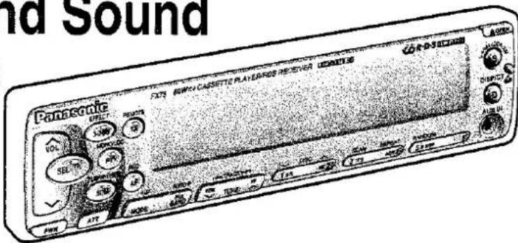
Power and Sound Controls
Power
If the car is not already running, turn the key in the ignition until the accessory indicator lights.
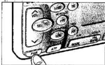
Press PWR to switch on the power.
Press and hold PWR again to switch off the power.
Note: When power is switched on for the first time, demonstration display appears. To release this display, press S (S-ANALYZER/DIM).

Volume
Press "VOL∧" or "∨VOL" to increase or decrease volume.

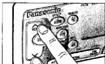
Press "VOL" or "∨VOL" for more than a half second to sequentially change numeric levels on the display.
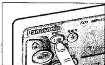
3•DSB (3-Dimensional Surround and Super Bass) and Loud Switching
① Press 3·DSB to switch on or off 3·DSB and Loud as follows.

flowchart
graph LR
    A["3-DSB OFF\nLOUD OFF"] --> B["3-DSB ON\nLOUD OFF"]
    B --> C["3-DSB OFF\nLOUD ON"]
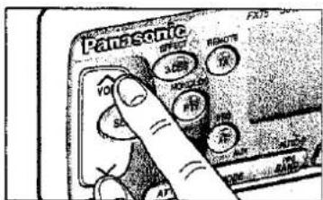
② Press and hold 3•DSB for more than 2 seconds when 3•DSB is ON, a degree of effect can be selected. (except for the case when you listen to a broadcast with virtual stereo effect.)
Press ∧VOL∨ to select one of the 10 degrees (0 through 9).
3·DSB System
It is a new sound system combining 3-dimensional sound from two front speakers with rear channel super bass when you receive stereo broadcast.
3•DSB also gives you a sound with virtual stereo effect from 4ch speakers when you receive AM monaural broadcast or FM broadcast in the monaural mode.
The 3•DSB employs Spatializer® ICs of Desper Products, Inc.
Note: This unit is equipped with anti-volume-blast circuit which serves as an automatic volume level adjuster so that you will not be deafened with sudden loud volume.
This system operates as below. When PWR is first pressed to switch on, the volume level is low. After that, the volume level gradually returns to the level when the switch is turned off.
Anti-volume-blast circuit is not effective when volume level is lower than position 20 at the display.
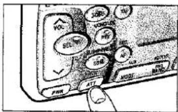
Attenuator
- Press ATT to decrease volume to about 1/10 of the previous level.

- Press ATT again to cancel.
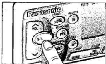
Changing Audio Modes
Press SEL to switch the audio mode in the following order.

flowchart
graph LR
    A["Normal Mode"] --> B["VOL"]
    B --> C["BAS"]
    C --> D["TRE"]
    D --> E["BAL"]
    E --> F["FAD"]
    G["SUB"] --> H["↑"]
    H --> I["↓"]
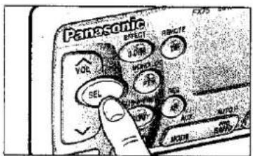
Bass and Treble
Press SEL to select the BASS (TREBLE) mode. Press "VOL" or "VOL" to increase or decrease the bass (treble) response.

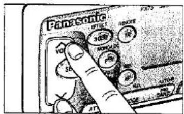
Balance
Press SEL to select the BALANCE mode. Press "VOL^" or "∨VOL" to shift the sound volume to the right or left speakers.

Fader
Press SEL to select the FADER mode. Press "VOL∧" or "∨VOL" to shift the sound volume to the front or rear speakers.

Note: When an audio mode (BAS/TRE/BAL/FAD) is selected but no operation is made within 5 seconds (2 seconds at VOL mode), the display will return to the normal operation mode. In such a case, press SEL again to select the control mode.
Power and Sound Controls continued
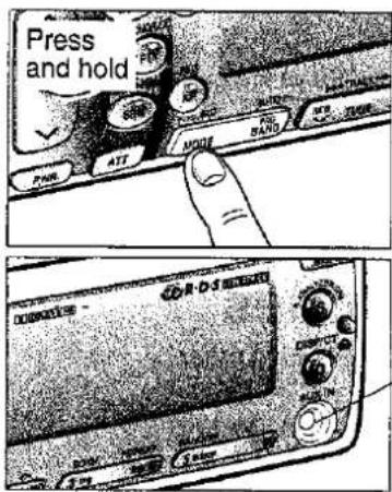
Selecting Auxiliary Source
① Press and hold MODE (AUX) for more than 2 seconds to select AUX Input mode.
AUX IN
② Connect the auxiliary equipment (any other appropriate equipment) to the AUX Jack.
AUX Jack
Canceling AUX Input mode
Press MODE (AUX) to resume the previous mode.
Sound Design Memory
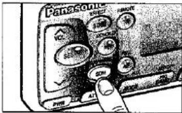
Sound Design Memory Mode Selection
A desired sound setting (except for VOL and ATT) can be memorized and recalled.
Press SDM to select the sound design memory mode.
SOUNR
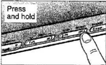
Sound Design Memory Input
- To preset a desired sound setting, press and hold the corresponding preset memory button (1 to 4) until the display blinks in sound design memory mode.
SOUND
- The preset memory buttons 5 and 6 are not valid for memory write.
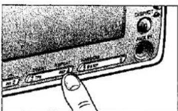
Sound Design Memory Call
- When a desired preset memory button is pressed in sound design memory mode, the corresponding sound setting is called out.
SOUND 4
The called preset number is displayed.
- The preset memory button 5 is recommended for setting.
- The preset memory button 6 is used to release all sound settings.
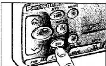
Canceling of Sound Design Memory Mode
Press MODE or SDM to change to the normal mode.
Note: When the sound design memory mode is selected but no operation is made within 5 seconds, the mode will return to the normal mode.
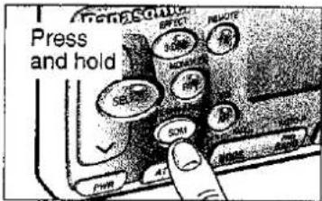
Sub-woofer Cutoff Frequency Switching
Press and hold SDM (SUB · W · FREQ) for more than 2 seconds to switch the Sub Woofer Cutoff Frequency Switching mode in the following order.
SUB WOOFER ON 80 Hz → SUB WOOFER ON 120 Hz

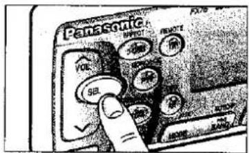
Sub-Woofer Volume
- Press SEL to select the Sub-Woofer Volume mode. Press "VOL" or "V/VOL" to increase or decrease the Sub-Woofer Volume.
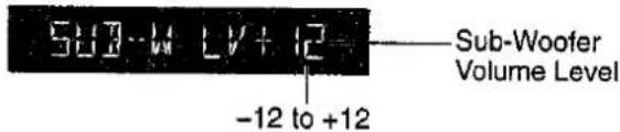
- Press "VOL" to mute the Sub-Woofer output at SUB 1 mode. (SUB-W LV-12)
Display Controls
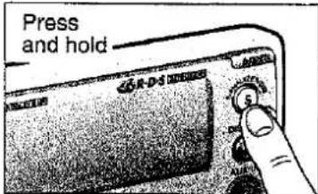
Dimmer Switching
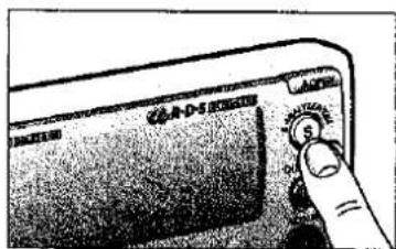
Press and hold S (S · ANALYZER/DIM) for more than 2 seconds to change the brightness of the LCD from one level to another in a cycle of 3 levels as follows:

flowchart
graph LR
    A["Dimmer 1 (Bright)"] --> B["Dimmer 2 (Medium)"]
    B --> C["Dimmer 3 (Dark)"]
natural_image
Illustration of a hand pressing down on a device with a rotary knob (no text or symbols visible)Spectrum Analyzer Display Switching
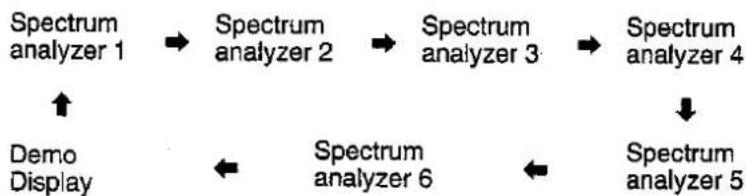
Press S (S · ANALYZER/DIM) to change the spectrum analyzer display from one spectrum analyzer to another in a cycle of 6 kinds plus demonstration mode.
flowchart
graph TD
    A["Spectrum analyzer 1"] --> B["Spectrum analyzer 2"]
    B --> C["Spectrum analyzer 3"]
    C --> D["Spectrum analyzer 4"]
    D --> E["Spectrum analyzer 5"]
    E --> F["Spectrum analyzer 6"]
    F --> G["Demo Display"]
Radio Basics
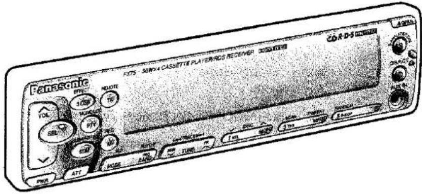
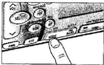
To change to Tuner Mode
Press MODE to switch the operation mode in the following order. ① In case of local control

Press and hold MODE (AUX) for more than 2 seconds to select AUX Input mode.
② In case of remote control

FM1 8750
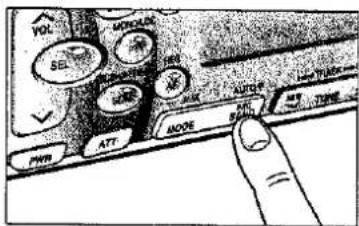
Selecting a Band
Press BAND to select the bands in the following order. "ST" indicator lights if the station is broadcasting in stereo.

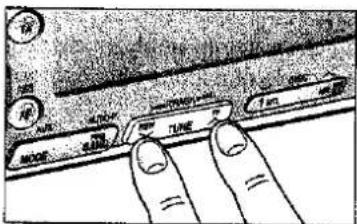
Manual Tuning
Press "∨TUNE" or "∧TUNE" to move to a lower or higher frequency.
FM1 8750
Press and hold "VTUNE" or "TUNE" to move to a lower or higher frequency rapidly.
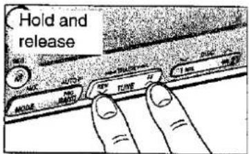
Seek Tuning
Press and hold "√TUNE" or "∧TUNE" for more than a half second, then release. The radio automatically stops on the next station.
Preset Station Setting
Up to 24 stations can be preset in the station memory as follows;
| FM1 | FM2 | FM3 | AM(LW/MW) |
| 6 stations | 6 stations | 6 stations | 6 stations |
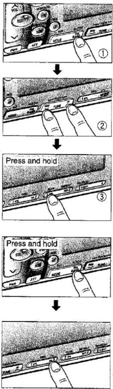
flowchart
graph TD
    A["Start"] --> B["Press and hold"]
    B --> C["End"]
    style A fill:#f9f,stroke:#333
    style B fill:#ccf,stroke:#333
    style C fill:#cfc,stroke:#333
Manual Station Preset
① Press BAND to select a desired band.
② Use manual or seek tuning to find a station that you want to program into memory.
③ Press and hold one of the station selector buttons 1 through 6 for more than 2 seconds until the display blinks.
Repeat the process to set other stations for the FM1 to AM bands.
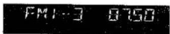
Preset Channel Indicator
Note: You can change the memory setting by repeating the above procedure.
Tuning in a Preset Station
Press any of the buttons 1 through 6 to tune in the station preset by the above steps ① to ③.
Caution: For safety reasons, do not attempt to program while driving.
Auto Station Preset
Select a band, press and hold BAND (AUTO · P) for more than 2 seconds.
- The 6 strongest available stations will be automatically set in memory on preset buttons 1 through 6.
- Once set, the preset stations are sequentially scanned for 5 seconds each.
- Press the appropriate preset button for the station you want to hear.
Radio Basics continued
MONO/LOCAL Selection
- Much Interference is reduced during a weak FM stereo broadcasts when MONO is ON. (Only for FM mode)
- Searching stops automatically at a strong wave station only when LOCAL is ON.
Press PTY (MONO/LOC) to switch the mode in the following order.
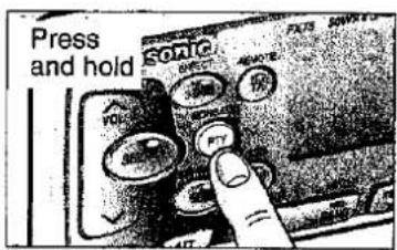
① During FM broadcasts
Press and hold PTY (MONO/LOC) to switch the mode in the following order. Release your finger at the desired mode.

flowchart
graph LR
    A["MONO OFF\nLOCAL OFF"] --> B["MONO ON\nLOCAL OFF"]
    B --> C["MONO ON\nLOCAL ON"]
    C --> D["MONO OFF\nLOCAL ON"]
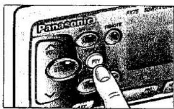
② During AM broadcasts
Press PTY (MONO/LOC) on or off the LOC mode as follows.
LOCAL OFF ↔ LOCAL ON
RDS (Radio Data System) Reception
Many FM stations are broadcasting added data compatible with RDS. This radio set offers convenient functions using such data.
AF (Alternative Frequency)
When receiving condition becomes poor, an RDS station with the same program will be automatically selected.
EON (Enhanced Other Networks)
When EON data is received, the EON indicator lights and the TA and AF functions are expanded.
TA: Traffic information from not only the station now tuned in to but also other stations of the same network can be received.
AF: The frequency list of the RDS stations preset by received EON data is updated.
PS (Program Service Name)
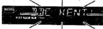
When an RDS station is received, the RDS indicator lights and automatically displays the name of that station instead of the frequency. When D (DISP/CT) is pressed during PS display, the frequency is displayed for 3 seconds, then PS display returns.
PI (Program Identification)
If a preset RDS station is poor in receiving condition when it is selected, the automatic seek (PI Seek) starts to seek the same program and tune in to it.
PTY (Program Type)
Program type Identification signal
Example : News, rock, classical music
TA (Traffic Announcement)
When an FM station that periodically provides the latest traffic information is received, the TP indicator lights. If TA ON is set, FM traffic information automatically interrupts your listening to a tape, CD changer or AUX source until it ends, then you will listen again to whatever you have been listening to.
Best Station Research
If a preset RDS station is in poor condition of reception when you try to tune in to it, the best frequency is selected from the AF list of that station.
REG (Region)
The AF, Best Station Research, PI Seek functions will be as follows:
REG ON : The frequency changes only with the same regional program. This function is mainly used while driving in the same area, for example, in a city.
REG OFF: The frequency changes even with a different regional program if the station is in the same network. The broadcast may be different depending on the case. This function is mainly used when driving far from one region to another.
WHAT PROVIDES EON CAPABILITIES
EON lets the radio set take advantage of RDS information much more than before. It constantly updates the AF list of all presets, including the station currently tuned in to. So, even if you change preset far from home, you will be able to receive the same station at an alternative frequency, or another station serving the same program if any. EON also keeps track of locally available TP stations for quick reception.
Note: When you're in "AF ON" mode, auto preset memory only works for RDS station. When in "TA on" mode, it only works for TP stations. To make auto preset for ordinary stations, cancel AF mode and switch to TA off in advance.
RDS (Radio Data System) Reception continued A. Basic Operation in RDS Reception (PS, AF, CT, PI)
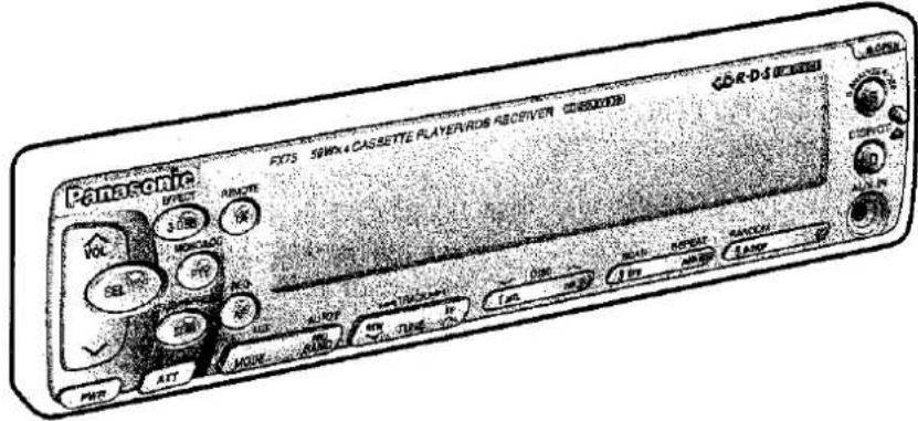
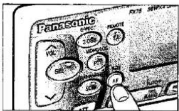
RDS Reception
Press AF when receiving a station in the FM1, FM2 or FM3 band.
- The operating mode changes to AF ON or AF OFF, respectively.

- Select AF ON if you wish to use the AF network of an RDS station. Best station research is activated at the same time.
- Select AF OFF if the AF network of an RDS station is not necessary.
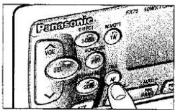
To Change AF Mode
Press AF to change AF ON and activate Best Station Research at the same time. (3 seconds maximum)
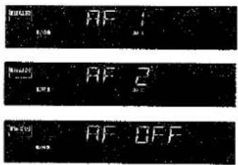
Notes:
- Default mode is AF1.
- AF1 has a low level of AF operating sensitivity in urban areas. Therefore, AF dose not frequently operate even of sensitivity is temporarily lowered between skyscrapers, for examples.
- AF2 is for suburban areas with a higher level of sensitivity than AF1.
For Seek Tuning, RDS Station Preset, Tuning in a RDS preset station, and Auto RDS Station Preset, please refer to Radio Basics (page 10 to 12).
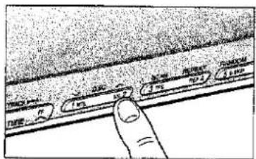
RDS seek tuning (PI seek)
The PI seek function may be used if an RDS station selected from the memory is poor in receiving condition. Press the preset button again for the station now tuned in to.
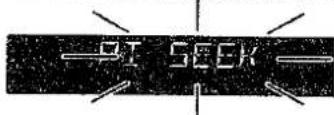
PI Seek: If Best Station Research fails in selecting the best station, the PI seek function operates to automatically tune in to the same program.
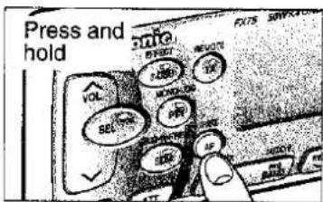
Region (REG) Switching
Press and hold AF(REG) for more than 2 seconds in AF mode to alternately select REG ON and REG OFF.

Note:
If you wish to stay with the same program, keep REG ON. If you keep REG OFF, there is a higher possibility of returning in to an AF station in better receiving condition.
The relationship of the PI seek function with REG ON and REG OFF is as described above.
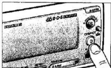
Changing Display
Press D(DISP/CT) to change the display.
(Frequency display continues for only 3 seconds, returning to PS display after that.)
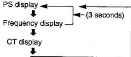
flowchart
graph TD
    A["PS display"] --> B["Frequency display"]
    B --> C["CT display"]
    C --> D["(3 seconds)"]
Clock Time (CT) System
The CT (24-hour) system may not properly operate in areas where RDS CT service is not available. Once CT service is received, the CT system keeps operating. "NO CT" is displayed in areas where no CT service is available.

Clock Display
Press D (DISP/CT) to indicate the clock display.
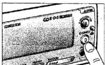
CQ-FX75EW
RDS (Radio Data System) Reception continued
Initial Time Setting
Press BAND to change to AM mode.
① Press D(DISP/CT) "AM NO CT" is displayed.
② Press and hold D(DISP/CT) again for more than 2 seconds "hours" blinks indicating the time setting mode is activated.
③ To set hours, press "√TUNE" or "∧TUNE".
④ Press D(DISP/CT) again for minutes setting.
⑤ To set minutes, press "√TUNE" or "∧TUNE".
Hold "√TUNE" or "∧TUNE" change numbers rapidly.
⑥ When set the time, press D(DISP/CT).
Notes:
- If CT display is kept on, it remains on even if PWR and ACC are tuned off and back on again.
- In other mode, press D (DISP/CT) to get RDS CT-service.
B. TP Reception
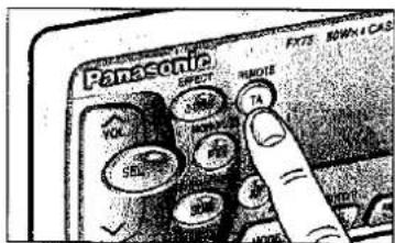
Select traffic information (TA on) mode
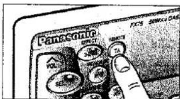
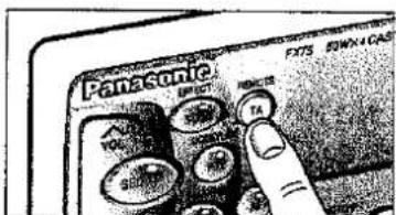
Press TA to switch ON and keep it there when you wish to listen to traffic information. Press TA to switch OFF when no traffic information is needed.
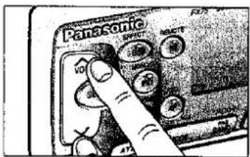
Volume Setting (Only for TAPE/CD-C/AUX TA on mode)
Adjust the volume as desired using "VOL∧" or "∨VOL" while receiving traffic announcement. (TA)
After volume for traffic announcement (TA) is set, the difference between normal volume and TA volume is automatically stored in the memory (up to 5 levels) so that next traffic information will be received at the preceding TA volume which may be higher or lower than normal volume.
Normal volume can be changed up to 5 levels upward or downward.
If an adjusted level of volume is over 40 or less than 0, any further change will not be made.
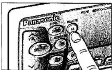
When receiving a station other than TP station (including EON stations)
A traffic information station is automatically searched for and the radio automatically stops the next available TP station. EON Capabilities:
EON lets the radio take advantage of much more RDS information than before. It constantly updates the AF lists for all switch presets far from home, you will receive an alternative frequency for the same station, or another station carrying the same program, when such exists. EON also keeps track of locally available TP station.

TP Seek Tuning
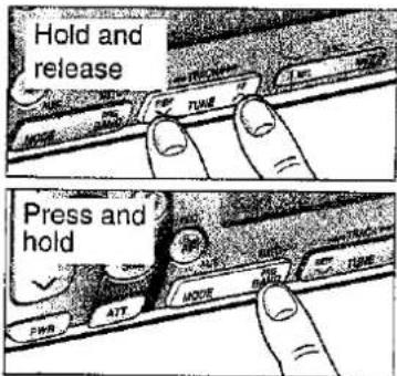
Press "VTUNE" or "TUNE" for more than a half second, then release. The radio automatically stops on the next available TP station.
Auto TP Station Preset
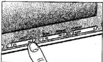
Press and hold BAND (AUTO · P) for more than 2 seconds. The six strongest available TP stations are automatically set in memory on the preset button 1 through 6.
Once set, the preset stations are sequentially scanned for 5 seconds each.
Tuning in a TP station preset
Press any of the preset buttons 1 through 6 that you want to hear. And then Best Station Research function is activated to automatically select the strongest available frequency for the TP station (through the built-in frequency) lists, if reception is weak.
Muting TA on
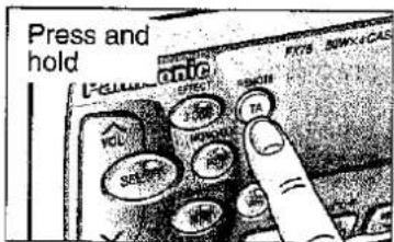
Press and hold TA for more than 2 seconds to light "TA on".
Then Traffic Announcement (TA) function is activated to operate, allowing you to listen to only Traffic Program whenever it is available.
Muting TA on canceling (Muting TA on → TA on)
Press TA again.
Press "VOL∧" to increase the volume level.
TP Auto Search
If receiving conditions are poor when TA is on during muting and if there is no other alternative frequency in the same network, a traffic announcement station in good receiving condition is automatically searched for.
Tape/CD · C/AUX TA on
Press TA during tape, CD changer, AUX mode.
TA on mode is selected while listening to the source in that mode, wait for Traffic Announcement to being.

Switching to TA off Mode
Select either one of the following steps.
- Press TA when TA is ON.
- Press and hold TA for more than 2 seconds when Muting TA is ON.
- Press TA when tape/CD-C/AUX TA is ON.
RDS (Radio Data System) Reception continued C. PTY Reception
(There are some areas where PTY service may not be available.)
Switching to PTY mode
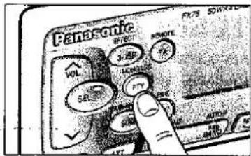
Press PTY to select PTY display mode, and the PTY of the broadcast now received is displayed.
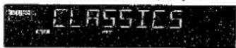
"NO PTY" is show if there is no corresponding program type.

Changing PTY Display Language
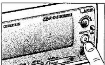
Pressing D(DISP/CT) each time in PTY mode to alternate the language between English and Swedish.

Program Type Selection
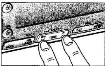
Press "∨TUNE" or "∧TUNE" to select the program type in sequence as follows.
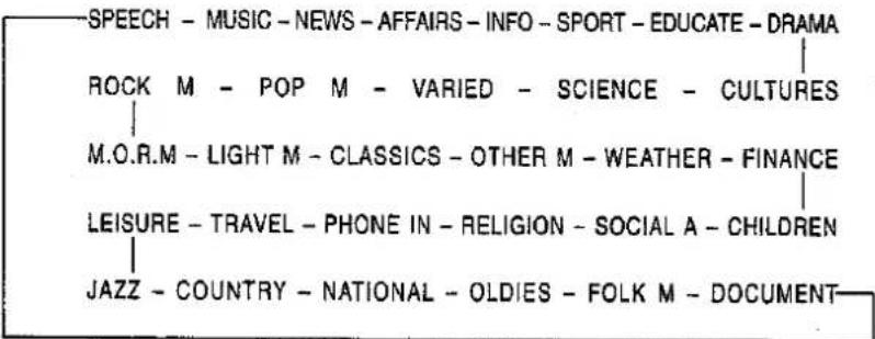
When the desired selection has been made, press BAND. Then automatic seek will start to tune into the station broadcasting the selected program type.
Note :
Seek tuning does not operate as long as "NO PTY" is displayed.
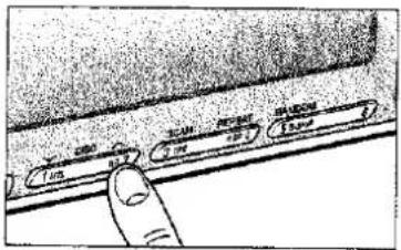
TABLE of PTY CODE and Program Type
Press any of the preset button 1 through 6 that you want to desire the program type. Those buttons are already stored program types as below. (Initial setting)
| Preset NO. | 1 | 2 | 3 | 4 | 5 | 6 |
| Program Type | NEWS | SPEECH | SPORTS | POP. MUSIC | CLASSICS | MUSIC |
| Display | NEWS | SPEECH 2 | SPORT 3 | POP M 4 | CLASSICS 5 | MUSIC 6 |
| NEWS | AFFAIRSINFOEDUCATEDRAMACULTURESSCIENCEVARIEDWEATHERFINANCECHILDRENSOCIAL ARELIGIONPHONE INTRAVELLEISUREDOCUMENT | SPORT | POP M | CLASSICS | ROCK MM.O.R.MLIGHT MOther MJAZZCOUNTRYNATIONALOLDIESFOLK M |
Program Type Preset
Press and hold one of the buttons 1 through 6 for more than 2 seconds to preset the desired program type selection in that button.
Tuning in a PTY Preset Station
Press any of the preset buttons 1 through 6 that you want to hear.
RDS (Radio Data System) Reception continued
Searching for PTY
① Select the desired station from among those preset in the preset number buttons 1 through 6. Then, the preset PTY and that preset number are displayed for 5 seconds.

② While the desired type from 6 presets is displayed, take either of the following two steps.
A) Press the same preset button again.
B) Press BAND.
If the desired PTY station is available, it is directly received. If it is not, "NO PTY" blinks and the radio returns to the station that was received before the search.

Press the same button again to cancel.
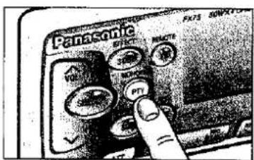
Canceling of PTY Mode
Press PTY to cancel.
The set returns to the state existing before PTY mode while the receiving frequency remains unchanged.
Emergency Announcement Reception
(Some areas are not covered by emergency announcement service.) If an emergency announcement is broadcast during tape/CD changer/AUX mode, the radio is automatically selected to receive the emergency announcement. "ALARM" blinks.
Cassette Tape Player Basics
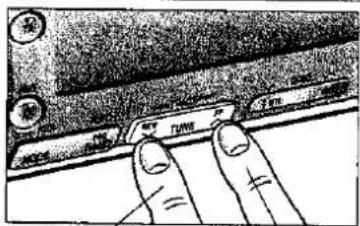
REWIND
FAST FORWARD
Loading a Cassette
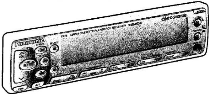
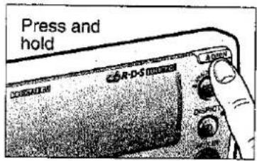
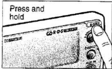
① Press and hold ▲ (OPEN) to open the front panel.
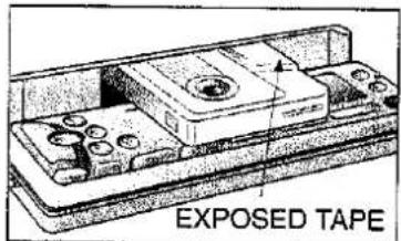
② Insert the cassette with the exposed tape side facing to the right and the front panel close automatically. Each time press ▲ (OPEN) to change the slope of the front panel in 3 levels.
Note:
- If the front panel is open with power OFF, the PWR button only is valid.
- If the front panel is open with power ON, cassette insertion and ▲ (OPEN) button only are valid.
TAPE PLAY
PROGRAM INDICATOR
Rewind and Fast Forward
Press either "◀◀ TRACK" to rewind or "TRACK ▶▶" to fast forward the tape.
TAPE FF
- If you rewind the tape fully, it will play same program side again.
- If you fast forward to the end, play will resume from the beginning of the other side of the tape.
To stop rewind or fast forward, press PRG (BAND).
Changing Sides
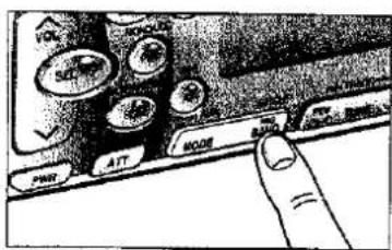
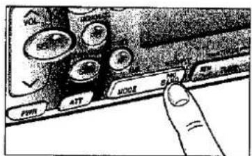
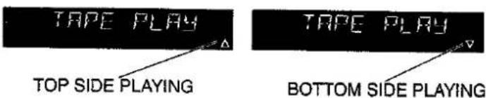
Press PRG (BAND) to switch to the program on the other side of the tape.
CQ-FX75EW
Cassette Tape Player Basics continued
Ejecting the Tape
Press and hold ▲ (OPEN) to open the front panel, and the cassette will eject for removal. After removing the tape, press ▲ (OPEN) again to close it and the previous mode of operation will be resumed.
Notes:
- If power is switched off before ▲ (OPEN) is pressed, the cassette will not eject. Switch on the power again and press and hold ▲ (OPEN) to eject the cassette.
- The cassette tape should always be removed from the cassette slot when not in use.
natural_image
Close-up of a finger pressing a button on a device panel (no visible text or symbols)Blank Skip
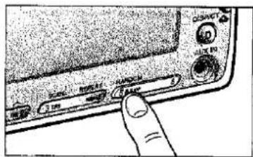
- Press 5 (B · SKIP) to skip long unrecorded portions on the tape.
- Press 5 (B · SKIP) again to cancel.
Notes:
- "B · SKIP" indicator lights. However, the blank skip operation will not work if REPEAT is on. The repeat function has priority over that of the blank skip function.
- Also the blank skip operation will not work when the unrecorded portions of the tape is less than 15 seconds.
Repeat Play
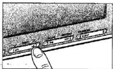
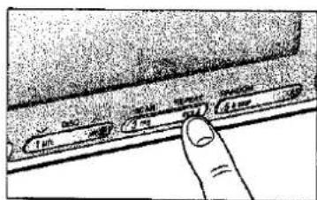
- Press 4 (REP) to repeat the same music you are now listening to.
- Press 4 (REP) again to cancel.
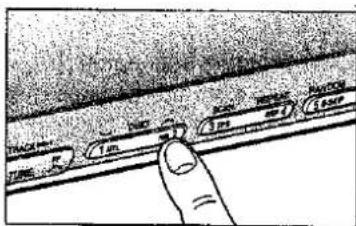
Dolby Noise Reduction
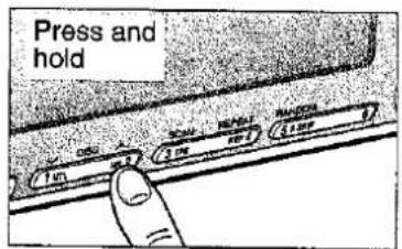
- Press 2 (NR) once to set the Dolby B NR mode. Set the Dolby B NR mode when playback a tape recorded with Dolby B Noise Reduction.
- To cancel the Dolby NR mode, press the button again.
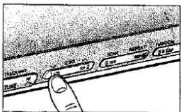
Metal Tape Mode
- Press 1 (MTL) when playing metal or chromium dioxide (CrO2) tapes.
- Press 1 (MTL) again to cancel.
Note: Playing non-metal tapes in MTL mode causes high frequency imbalance, which affects tone quality.
↓
or
TPS Operation (Tape Program Search)
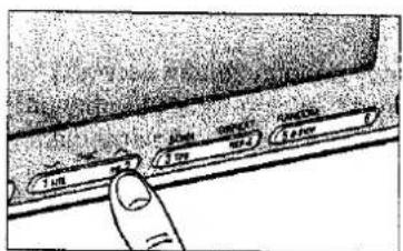
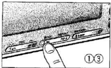
① Press 3(TPS) to activate the tape program search mode.
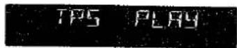
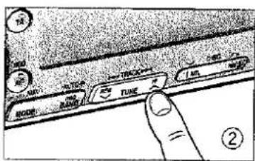
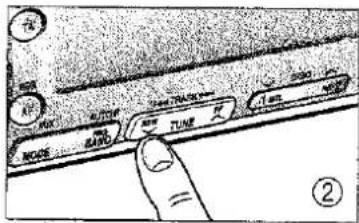
② From the current selection, decide which program you want to select. Now, press "FF(∧TUNE)" several times forward (up to 9 programs) or press "REW(∨TUNE)" several times backward (up to 8) to select the corresponding program number.
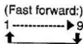
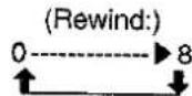
EX1. To select the current program again press 3 (TPS), and press "√TUNE" once.
EX2. To select the 1st program backward of the current selection, press 3 (TPS) once, and press "V TUNE" two times.
EX3. To select the next program, press 3 (TPS) and press "∧TUNE" once.
EX4. To select the 3rd program forward of the current selection, press 3 (TPS) once, and press “^TUNE” three times.
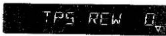

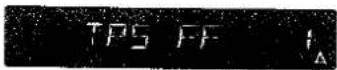
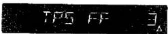
③ Press 3 (TPS) again to cancel.
Note:
The TPS mode may not work correctly in the following cases. This, however, does not mean that the unit is defective.
- There is an interval less than 4 seconds or having a high level of noise or hum between programs.
● There is particularly low-level passage during the program.
Note: To maintain your cassette player in top condition, avoid using tapes that are longer than 90 minutes (C-90).
"For Inserting a Cassette Tape"
If you insert into the unit a cassette with a loose tape caused by forcing it into cassette with a finger or the like, the cassette may not be properly reproduced. In such a case, eject the cassette, make the tape tight, then insert it back into the deck.
CD Changer Basics
Note:
CD changer functions are applicable to units with optional CD changer unit. (sold separately)
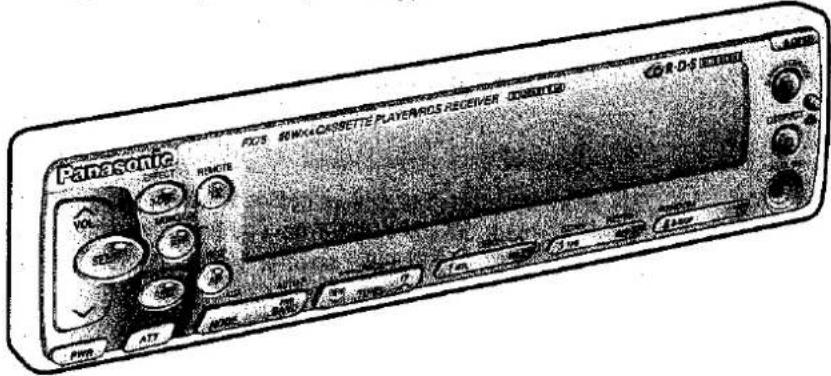
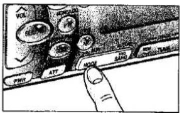
To start the CD Changer
While CD changer is connected, press MODE to change into the CD changer mode and playback starts automatically.
1-0: 10'35
natural_image
Close-up of a finger pressing down on a surface with two small objects (no text or symbols visible)Selecting a Disc
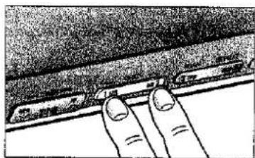
Press "√DISC" or "DISC∧" to select discs in descending or ascending order.
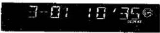
3·01 10'35¢
Then, the selected disc will start to play from the first track.
Selecting a Track
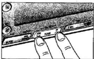
- Press "TRACK ►►" once to go to the next track.
- Press "◀◀ TRACK" once to play from the beginning of the current track. Press twice to play the previous track.
- Press repeatedly to skip the desired number of tracks.
Searching a Track
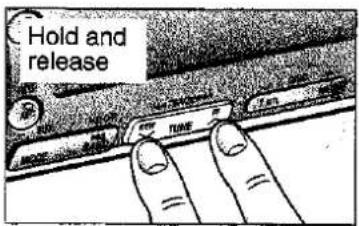
- Press and hold "TRACK ▶" or "◀ TRACK" for more than a half second to activate fast forward or reverse through a track.
- Release "TRACK ►►" or "◄◄ TRACK" to resume the normal CD play.
natural_image
Close-up of a finger pressing down on a surface with two buttons (no text or symbols visible)Repeating a Track
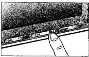
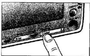
- Press 4 (REPEAT) to repeat the current selection.
- Press 4 (REPEAT) again to cancel
natural_image
Close-up of a finger pressing down on a device panel (no visible text or symbols)Random Selection
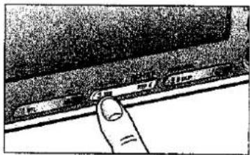
- Press 5 (RANDOM). A random selection of music is played from all available tracks.

- Press 5 (RANDOM) again to cancel.
Note:
The "∨DISC" or "DISC∧" is operated, has priority over that of Random play mode. The Random mode will stop and the disc select function will operate once the "∨DISC" or "DISC∧" is pressed.
natural_image
Close-up of a finger pressing down on a surface with a small object on the edge (no visible text or symbols)Scanning Tracks
- Press 3 (SCAN). The display blinks and the first 10 seconds of each track on the discs play in sequence.
- Press 3 (SCAN) again to cancel.
Scanning Discs
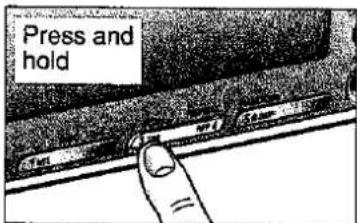
- Press and hold 3 (SCAN) for more than 2 seconds. The 1st track of all the discs in the magazine is played for 10 seconds each.
- Press and hold 3 (SCAN) again for more than 2 seconds to cancel.
natural_image
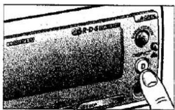
Close-up of a hand pressing down on a device with a screen and control knob (no visible text or symbols)Changing the Display
Press D(DISP/CT) to switch the display in sequence as follows.
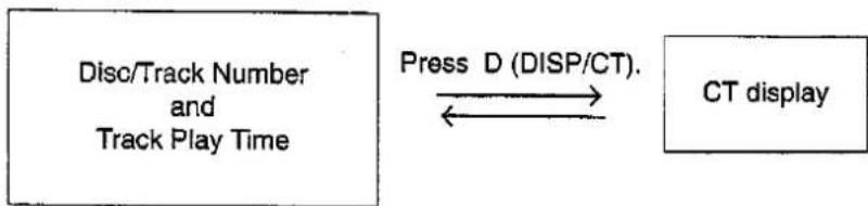
flowchart
graph LR
    A["Disc/Track Number and Track Play Time"] --> B["Press D (DISP/CT)."]
    B --> C["CT display"]
CD Changer Basics continued
Error Display Messages
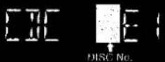 | Displays when the compact disc is dirty or upside down. Selects the next available compact disc. |
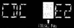 | Displays when compact disc is scratched. Selects next available compact disc. |
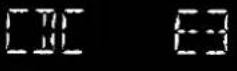 | Displays when the unit stops operating for some reason. Press RESET on the CD Changer (optional). |
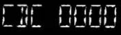 | Displays when there is no disc in the magazine. |
Remote Control Basics
Battery Replacement:
1. Remove the battery holder.
Pull the holder by the Position B while pushing Position A in the direction indicated by the arrow.
2. Replace the battery.
Set a new battery properly with (+)side up as illustrated.
3. Insert the battery holder.
Push in the holder to the original position.
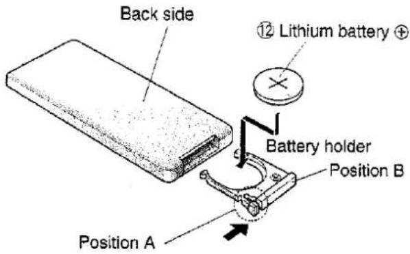
Note on Batteries:
Old batteries must immediately be removed and disposed.
Battery Information:
- Designated Battery: Panasonic Lithium Battery (CR2025)
- Battery Life: 6 months with normal use (in normal room temperature)
Caution:
Improper use of batteries may cause overheating, explosion or ignition, resulting in jury or fire. Battery leakage may cause damage to the unit.
- Do not disassemble or short the batteries. Do not throw the batteries into the fire.
- To avoid the risk of accident, keep the batteries out of reach of children.
Names of Main Controls:
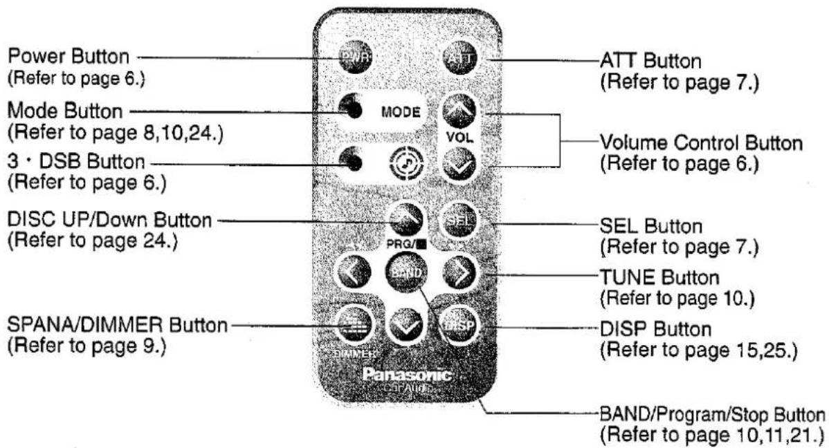
CQ-FX75EW
Anti-Theft System
This unit is equipped with a removable face plate. By removing this face plate, the radio becomes totally inoperable. The security indicator will blink.
To Remove the Removable Face Plate
① Switch off the power.
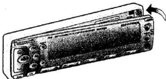
② Press the release button (▲). The removable face plate will be released.
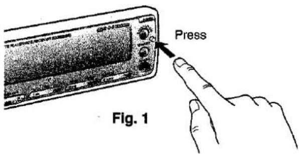
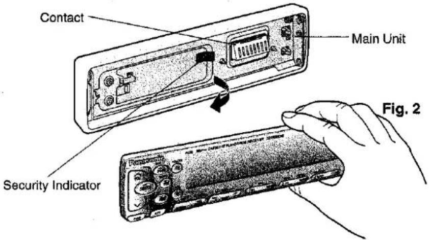
③ Remove the removable face plate by pulling on the right side of the unit. Place the removable face plate in a supplied case.
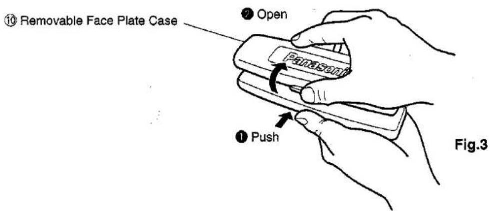
④ As shown in Fig.3, gently push the lower side of the case and open its cover. Keep the removable face plate in the case. Then, you can bring the plate safely.
To install the Removable Face Plate
① Slide the left side of the removable face plate in place.
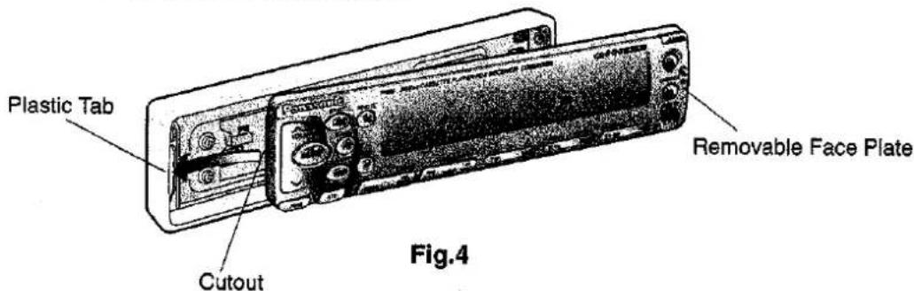
② Press the right end of removable face plate until "click" is heard.
natural_image
Illustration of a Panasonic electronic device with ports and an arrow indicating rotation (no text or symbols on the device itself)Fig.5
Caution:
- Before removing the removable face plate, make sure the power is off.
- This removable face plate is not water-proof. Do not expose it to water or excessive moisture.
- Do not remove the removable face plate, while driving your car.
- Do not place the removable face plate on the dashboard or nearby areas where the temperature rises to high levels.
- Do not touch the contacts on the removable face plate or on the main unit, since this may result in poor electrical contacts.
- If dirt or other foreign substances get on the contacts, wipe them with a clean, dry cloth.
- When installing or removing the removable face plate, keep the front panel closed. The removable face plate cannot be installed or removed when the front panel is open. Its forcible mounting or removal will cause trouble.
Anti-Theft System continued
Warning Alarm
Caution
This car radio is equipped with an integrated Warning Alarm in order to make robbery more difficult. But it has to be secured that the installation will be properly done so that the Warning Alarm may work in a perfect way. Concerning the installation the following points have to be observed:
- The supplied mounting collar has to be firmly fixed with the mounting tabs to the dashboard.
- The radio has to be put into the mounting collar in that way that it exactly ends with the collar.
- Please make sure that the technical features (impedance and power) of the speakers installed correspond to the specifications of this car radio (see technical specifications).
Only when these three points are observed during the installation, the correct function of the "Warning Alarm" will be secured.
If the main unit is not correctly wired and installed, the system may accidentally sound the alarm.
Warning Alarm and Security Indicator
The security indicator blinks when the removable face plate is removed from the unit. Furthermore, the alarm will set off for 1 minute then reset when an attempt is made to remove the unit from the mounting collar.
Activate Warning Alarm and Security Indicator
- Press and hold SEL for more than 4 seconds when the power is ON. "ALRM ON" is displayed, and the security indicator and Warning Alarm turn ON.
Note: The ALARM mode is inactivated when it is shipped. - To check whether the unit is set in the ALARM ON mode, make sure that the security indicator blinks when the removable face plate is removed.
Display
| ALRM ON |
| ↑↓ |
| ALRM OFF |
Security Indicator
Warning Alarm
Panel Removal Alarm
Blinks
ON
ON
(Press and hold SEL for more than 4 seconds.)
OFF
OFF
OFF
Caution:
-
Warning Alarm system may not operate if the exclusive supplied mounting collar is not used. This mounting collar will set off the alarm when the unit is being removed.
If the main unit is not correctly wired and installed, the system may accidentally sound the alarm. -
When removing or installing the unit, make sure that it is in the ALARM OFF mode.
-
When the Warning Alarm is activated by mistake, or when you want to remove the unit, the Warning Alarm and the security indicator functions can be canceled by the following steps of procedure.
• Install the removable face plate.
- Disconnect the power connector.
Panel Removal Alarm
This alarm sounds to warn you not to forget to remove the panel before leaving your car. This function is activated when the security alarm is ON.
Installation
Preparation
- Before installation check the radio operation with antenna and speakers.
- Disconnect the cable from the negative (−) battery terminal (see caution below).
- The unit should be installed in a horizontal position with the front end up at a convenient angle, but not more than 30°.
Caution:
For installation to cars with trip or navigational computers, all electronic memory settings previously registered in the computer will be lost when the battery terminal is disconnected. For this type of car, battery could not be disconnected. Therefore, extra care should be taken to prevent short circuitting.
In-dash Installation
Installation Opening
In-dash installation can be done if the car's dashboard has an opening for this unit as shown in Fig.
- The car's dashboard should have a thickness of 4.5mm - 6mm in order to make the installation of the unit.
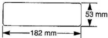
Fig. 1
Installation Precautions
This equipment, if possible, should be installed by a professional installer.
In case of difficulty, please consult your nearest authorized Panasonic Service Center.
- This system is to be used only in a 12-volt, DC battery system (car) with negative ground.
- Follow the electrical connection on page 34 carefully. Failure to do so may result in damage to the unit.
- Connect the power lead after other connections are made.
- Be sure to connect the YELLOW lead to the positive terminal (+) of the battery or fuse block (BAT) terminal.
- Insulate all exposed wires to prevent short circuitting.
Supplied Hardwares
| No. | Item | Diagram | Q'ty |
| 1 | Mounting Collar | 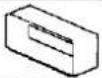 | 1 |
| 2 | Plain Washer (5 mmφ) | 2 | |
| 3 | Spring Washer (5 mmφ) | 2 | |
| 4 | Hex. Nut (5 mmφ) | 2 | |
| 5 | Rear Support Strap | 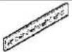 | 1 |
| 6 | Hex. Bolt(5 mmφ x 25 mm) |  | 1 |
| 7 | Toothed Lock Washer(5 mmφ) | 1 |
| No. | Item | Diagram | Q'ty |
| 8 | Mounting Bolt (5 mmφ) |  | 1 |
| 9 | Power Connector |  | 1 |
| 10 | Removable Face Plate Case |  | 1 |
| 11 | Remote Control Unit | [3706] | 1 |
| 12 | Lithium Battery (CR2025) |  | 1 |
| 13 | Dismounting Plate | [4278] | 1 |
| 14 | Trim Plate | [X482] | 1 |
| 15 | ISO Antenna Adaptor |  | 1 |
Installation continued
Installation Procedures
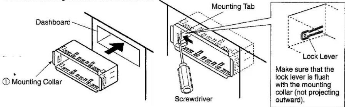
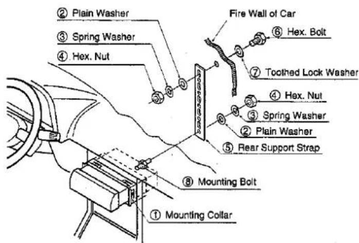
1. Secure the Mounting Collar ①.
Insert Mounting Collar ① into the car's dashboard, and bend mounting tabs out with a screwdriver.
2. Secure the rear of the unit.
a) Check the electrical connection by referring to this operating instructions.
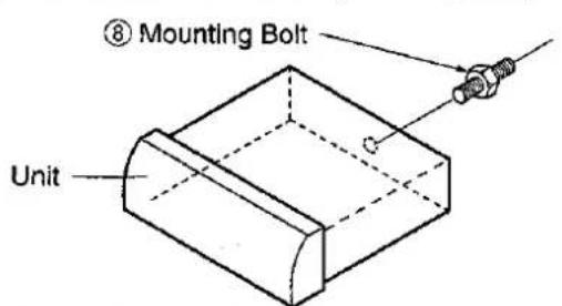
b) Connect the Mounting Bolt ⑧, using a suitable wrench.
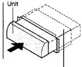
c) Insert the unit into Mounting Collar ① and push it in until "click" is heard.
d) Secure the rear of the unit to the car by either of the two recommended methods.
■ Using the Rear Support Strap ⑤
Affix one end of the Rear Support Strap ⑤ to the rear of the unit, and the other end to the Fire Wall of Car, or some other metallic area.
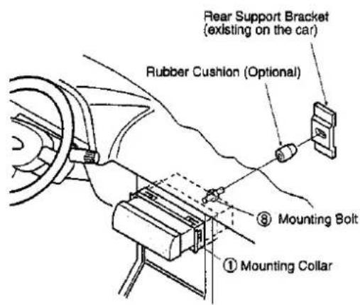
■ Using the Rubber Cushion (Optional)
(If there is an existing Rear Support Bracket on the Fire Wall of Car.)
Cover Mounting Bolt ⑧ on the rear of the unit with Rubber Cushion (Optional), and mount it into the existing Rear Support Bracket.
-
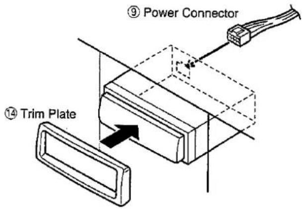
a) Plug the Power Connector ⑨. b) Install the Trim Plate ⑭.
-
After installation reconnect the negative (-) battery terminal.
To Remove the Unit
a) Remove the trim plate with a screwdriver as shown in the figure.
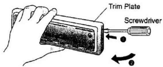
b) Pull out the unit while pushing the lock lever using Dismounting Plate ⑬. c) Remove the unit pulling with both hands.
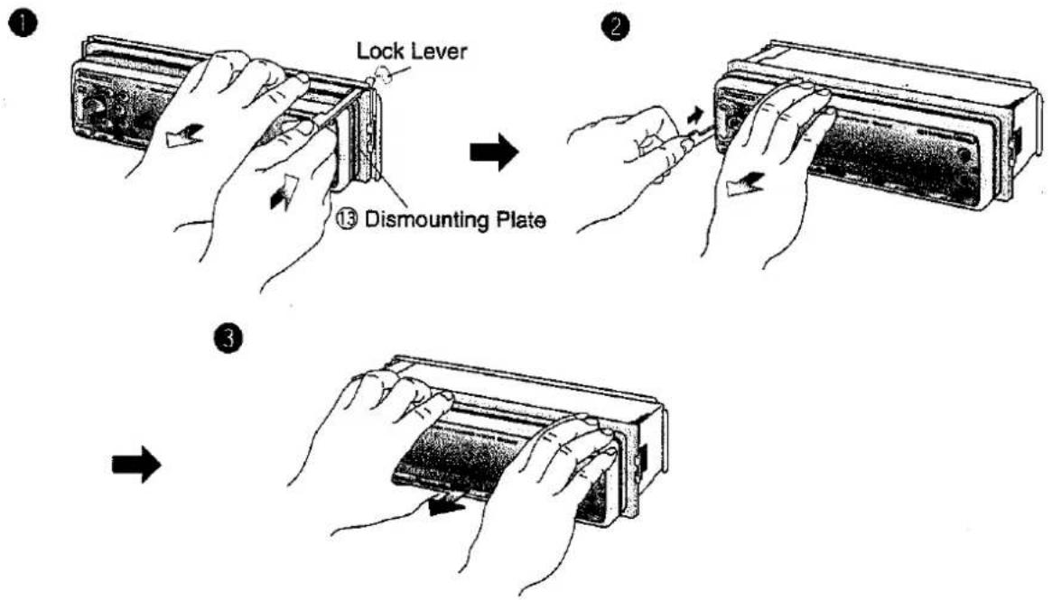
Note: Do not lose the Dismounting Plate. It will be needed to remove the unit from the car's dashboard.
Electrical Connection
Caution:
- Confirm the note on page 3, and make connections to the connectors on car side.
- To prevent damage to the unit, be sure to follow the connection diagram below.
- Remove the covering of the leads about 5 mm long from their end before connecting. (the cords except for ISO connector's cords)
- Do not insert the power connector into the unit until the wiring is completed.
- Be sure to insulate any exposed wires from a possible short-circuit from the car chassis. Bundle all cables and keep cable terminals free from touching any metal parts.
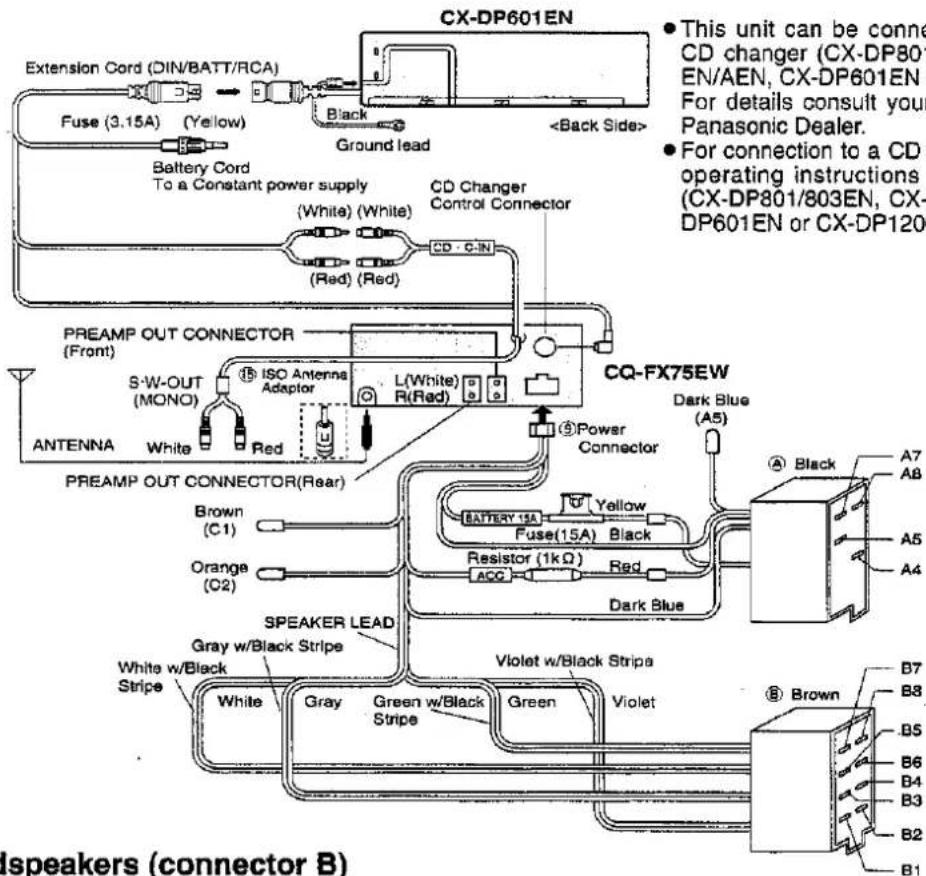
Loudspeakers (connector B)
| Left + | Left - | Right + | Right - | |
| Front | B5 (White) | B6 (White w/Black Stripe) | B3 (Gray) | B4 (Gray w/Black Stripe) |
| Rear | B7 (Green) | B8 (Green w/Black Stripe) | B1 (Violet) | B2 (Violet w/Black Stripe) |
A4
BATTERY LEAD (To Battery of Car) (Yellow)
Connect to the "BAT" terminal on the fuse block of the car. The power should be supplied continuously to the yellow leads regardless of the on/off position of the ignition key.
A5
MOTOR ANTENNA RELAY CONTROL LEAD (Dark Blue)
(To Motor Antenna) (Max. 500mA)
This lead is not intended for use with switch actuated power antenna.
AMP-RELAY CONTROL POWER LEAD
This lead is for connection to Panasonic power amplifier.
A7
POWER LEAD (Red)
Connect to the "radio" power line of the car or to the "IGN" or "ACC" terminal of the fuse block.
A8
GROUND LEAD (Black)
Connect to a well grounded metallic part of your car.
C1
Not Used
C2
TELEPHONE MUTE LEAD (Orange)
(To car telephone mute line)
TELEPHONE MUTE
The telephone mute lead, if connected to the car telephone mute line, will activate the muting circuit and the sound from the speakers cannot be heard while the telephone conversation is in progress.
Note: This telephone mute lead is for connection only to the radio mute line. Be sure to ascertain this because it will not work with other type of output system.
Speaker Connections
Caution:
- Use ungrounded speakers only.
- The speakers to be used with this unit should be able to handle more than 40W of audio power. If an optional amplifier is used, the speakers should be able to handle the maximum output power of the amplifier. Use of speakers with small input ratings can cause damage to the speakers.
- The speaker impedance should be 4 - 8 ohms. If the impedance is too large or too small, it affects the output and may cause damage to the speakers or this unit.
- Do not use 3-wire type speaker system having a common earth lead. Never connect the speaker cord to the body of the car. This unit uses the BTCL circuit, so each speaker should be connected separately using parallel vinyl insulated cords.
- The speaker cords and the power amplifier unit should be kept away (about 30cm apart) from the antenna and antenna extension cord.
- Follow the connection diagram below carefully. Failure to do so may cause damage to both unit and speakers.
- Unit will be damaged if speakers (Front, Rear) are not connected properly.

- Do not connect more than one speaker to one set of speaker leads.

Fuse
Be sure to use a fuse of the specified rating (15A) when replacing a blown fuse. Fuses with higher capacity ratings, use of any substitute, or connection without a fuse may result in a fire hazard or damage to the unit. If the replacement fuse fails, consult your nearest authorized Panasonic Service Center.
Maintenance
To clean the exterior of this unit, use a soft cloth to wipe the surface. Do not use benzine thinner or any other type of solvents.
Specifications
| General | |
| Power Supply | : DC 12V (11V - 16V), Test Voltage 14.4V, Negative Ground |
| Tone Controls | : Bass; ± 12dB at 100HzTreble; ± 12dB at 10kHz |
| Current Consumption | : Less than 2.5A (Tape mode, 0.5W 4-Speaker) |
| Maximum Power Output | : 40W x 4 (at 4Ω) |
| Power Output | : 20W x 4 (DIN45 324, at 4Ω) |
| Speaker Impedance | : 4 - 8Ω |
| Dimensions (Main unit) | : 178(W) x 50(H) x 150(D) mm |
| Weight (Main unit) | : 1.6 kg |
| FM Stereo Radio | |
| Frequency Range | : 87.5 - 108MHz |
| Usable Sensitivity | : 6dB/μV(S/N 30dB) |
| Stereo Separation | : 35 dB(at 1kHz) |
| MW Radio | |
| Frequency Range | : 531 - 1,602kHz |
| Usable Sensitivity | : 28dB/μV (S/N 20dB) |
| LW Radio | |
| Frequency Range | : 153 - 279kHz |
| Usable Sensitivity | : 32dB/μV (S/N 20dB) |
| Cassette Player | |
| Reproduction System | : 4-track, 2-program stereo |
| Tape Speed | : 4.76cm/sec. |
| FF/REW Time | : Less than 110 sec. (C-60) |
| Frequency Response | : 30 - 17,000Hz (Normal)30 - 18,000Hz (Metal) |
| Wow and Flutter | : 0.12% (WRMS) |
| Signal to Noise Ratio | : 52dB (Dolby B NR on; 62dB) |
Note:
Specifications and the design are subject to possible modification without notice due to improvements.
Certain audio features of this product manufactured under a license from Desper Products, Inc., Spatializer® and the circle-in-square device are trademarks owned by Desper Products, Inc.
Dolby noise reduction manufactured under license from Dolby Laboratories Licensing Corporation. "DOLBY" and the double-D symbol are trademarks of Dolby Laboratories Licensing Corporation.
- Operating Instructions 操作說明書
- Contents
- 目錄
- Precautions (ISO connector)
- Precautions
- Volume Level
- Car Washing
- Car Ventilation
- Power Supply
- Tape Mechanism
- Service
- About Preset Memory
- 注意事項
- 音量
- 洗車時
- 汽車通風
- 供電
- 磁帶機構
- 維修
- 關於預置記憶
- Power and Sound Controls
- Power
- Volume
- 3•DSB (3-Dimensional Surround and Super Bass) and Loud Switching
- 3·DSB System
- Attenuator
- Changing Audio Modes
- Bass and Treble
- Balance
- Fader
- Power and Sound Controls continued
- Selecting Auxiliary Source
- AUX IN
- Sound Design Memory
- Sound Design Memory Mode Selection
- SOUNR
- Sound Design Memory Input
- SOUND
- Sound Design Memory Call
- SOUND 4
- Canceling of Sound Design Memory Mode
- Sub-woofer Cutoff Frequency Switching
- Sub-Woofer Volume
- Display Controls
- Dimmer Switching
- Spectrum Analyzer Display Switching
- Radio Basics
- To change to Tuner Mode
- Selecting a Band
- Manual Tuning
- Seek Tuning
- Preset Station Setting
- Manual Station Preset
- Tuning in a Preset Station
- Auto Station Preset
- Radio Basics continued
- MONO/LOCAL Selection
- ① During FM broadcasts
- ② During AM broadcasts
- RDS (Radio Data System) Reception
- AF (Alternative Frequency)
- EON (Enhanced Other Networks)
- PS (Program Service Name)
- PI (Program Identification)
- PTY (Program Type)
- TA (Traffic Announcement)
- Best Station Research
- REG (Region)
- WHAT PROVIDES EON CAPABILITIES
- RDS (Radio Data System) Reception continued A. Basic Operation in RDS Reception (PS, AF, CT, PI)
- RDS Reception
- To Change AF Mode
- Notes:
- RDS seek tuning (PI seek)
- Region (REG) Switching
- Note:
- Changing Display
- Clock Time (CT) System
- Clock Display
- RDS (Radio Data System) Reception continued
- Initial Time Setting
- TP Reception
- Select traffic information (TA on) mode
- Volume Setting (Only for TAPE/CD-C/AUX TA on mode)
- When receiving a station other than TP station (including EON stations)
- TP Seek Tuning
- Auto TP Station Preset
- Tuning in a TP station preset
- Muting TA on
- Muting TA on canceling (Muting TA on → TA on)
- TP Auto Search
- Tape/CD · C/AUX TA on
- Switching to TA off Mode
- RDS (Radio Data System) Reception continued C. PTY Reception
- Switching to PTY mode
- Changing PTY Display Language
- Program Type Selection
- Note :
- TABLE of PTY CODE and Program Type
- Program Type Preset
- Tuning in a PTY Preset Station
- Searching for PTY
- Canceling of PTY Mode
- Emergency Announcement Reception
- Cassette Tape Player Basics
- Loading a Cassette
- Rewind and Fast Forward
- Changing Sides
- Cassette Tape Player Basics continued
- Ejecting the Tape
- Blank Skip
- Repeat Play
- Dolby Noise Reduction
- Metal Tape Mode
- TPS Operation (Tape Program Search)
- "For Inserting a Cassette Tape"
- CD Changer Basics
- To start the CD Changer
- Selecting a Disc
- Selecting a Track
- Searching a Track
- Repeating a Track
- Random Selection
- Scanning Tracks
- Scanning Discs
- Changing the Display
- CD Changer Basics continued
- Error Display Messages
- Remote Control Basics
- Battery Replacement:
- Remove the battery holder.
- Replace the battery.
- Insert the battery holder.
- Note on Batteries:
- Caution:
- Names of Main Controls:
- Anti-Theft System
- To Remove the Removable Face Plate
- To install the Removable Face Plate
- Anti-Theft System continued
- Warning Alarm
- Caution
- Warning Alarm and Security Indicator
- Activate Warning Alarm and Security Indicator
- Panel Removal Alarm
- Installation
- Preparation
- In-dash Installation
- Installation Opening
- Installation Precautions
- Installation continued
- Installation Procedures
- Secure the Mounting Collar ①.
- Secure the rear of the unit.
- ■ Using the Rear Support Strap ⑤
- ■ Using the Rubber Cushion (Optional)
- To Remove the Unit
- Electrical Connection
- A4
- BATTERY LEAD (To Battery of Car) (Yellow)
- A5
- MOTOR ANTENNA RELAY CONTROL LEAD (Dark Blue)
- AMP-RELAY CONTROL POWER LEAD
- A7
- POWER LEAD (Red)
- A8
- GROUND LEAD (Black)
- C1
- Not Used
- C2
- TELEPHONE MUTE LEAD (Orange)
- Speaker Connections
- Fuse
- Maintenance
- Specifications
Mærke : PANASONIC
Model : CQ-FX75
Kategori : Bilradio