Standard Control - Termostat Magnum - Gratis brugsanvisning og manual
Find enhedens vejledning gratis Standard Control Magnum i PDF-format.

Brugerspørgsmål om Standard Control Magnum
0 spørgsmål om dette apparat. Besvar dem du kender, eller stil dit eget.
Stil et nyt spørgsmål om dette apparat
Download vejledningen til din Termostat i PDF-format gratis! Find din vejledning Standard Control - Magnum og tag din elektroniske enhed tilbage i hånden. På denne side er alle dokumenter nødvendige for brugen af din enhed offentliggjort. Standard Control af mærket Magnum.
BRUGSANVISNING Standard Control Magnum
MAGNUM ^ keeps you warm
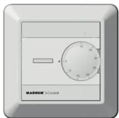
MAGNUM Standard Control
On/Off Thermostat
Installation manual
PLEASE READ THIS MANUAL CAREFULLY BEFORE INSTALLATION, AND STORE WITH OTHER WARRANTEE FORMS.
The MAGNUM Standard Control is an electronic thermostat with four functions: Room sensor, floor sensor, power regulator and room sensor with max./min. limiter. This thermostat can also be set up for setback temperature.
1. Startup
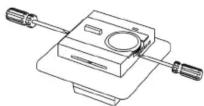
Remove the adjustment wheel with a screwdriver. The front cover can be removed by pushing in the locking clips on each side of the thermostat (as shown in fig.2). Be careful when doing this in order not to damage the thermostat. When the thermostat has been connected to the power source, push the on/off button. Never dismantle the thermostat when the power is switched on.
2. Sensor choice
When choosing a sensor type, the thermostat should not be connected to a power source.
- Floor sensor (standard)
Jumper placement: Covering the two pins on the left. Application: The temperature is regulated by the floor sensor.
- Room sensor
Jumper placement: Covering the two pins in the right Application: The temperature is regulated by the room sensor.
• Room sensor with limiter
Jumper placement: Covering the two pins on the right + the floor sensor connected
Application: The temperature is regulated by the room sensor, but the floor sensor overrides the room sensor if the floor temperature exceeds the maximum limit temperature. The limiter can be regulated between 20^ C and 30^ C. For parquet flooring, a maximum of 27^ C is recommended by most flooring manufacturers. Please follow the recommendations provided by your manufacturer.
- Power regulator
Jumper placement: Covering the two center pins
Application: The effect regulator has a 30 min cycle. The desired on/off interval can be set from 0 to 10, where each level increases the on-time by 3 minutes.
Example: When the thermostat is set to level 3, the heating element is switched on for 9 minutes, then off for 21 minutes in the 30 minute cycle. If the thermostat is set to level 6, the heating element is switched on for 18 minutes, then off for 12 minutes.


3. Connecting the thermostat
The thermostat must be connected to the power source according to the connection diagram. All heating systems must be equipped with a residual current disrupter with 30mA. Max load for the thermostat is 16A/3600W at 230V. If the load is higher, the thermostat must be connected to a contactor. The thermostat does not have galvanic insulation between high and low current. The sensor must therefore be considered as live (230V) and needs to be installed in accordance with the rules for high current installations and national installation requirements.
Caution: When reattaching the thermostat cover, make sure the ventilation on the top and bottom of the thermostat is not covered up.
4. Setback temperature
The Multireg thermostat does not have a built-in setback temperature option, but by connecting an external timer to the S and L clamps, the temperature can be lowered by 3^ C at desired times.
5. Calibrating the temperature
When connecting the floor heating system for the first time, the temperature should be set at a maximum of 15^ C to 20^ C. The thermostat should be calibrated after 2-3 days. Pull out the adjustment wheel carefully (without turning it) until it comes loose. Use a thermometer to check the actual temperature, and push the adjustment wheel back onto the thermometer in accordance with the measured temperature. If the floor heating has been switched off during the summer, this procedure should be repeated when it is switched back on.
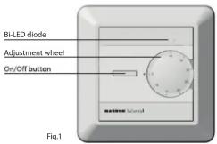
6. Bi-LED diode
- Green light when the thermostat is in a standby mode.
- Constant red light when the relay is engaged and the power is on.
- Blinking red light when there is a sensor malfunction or the floor sensor is disconnected.
7. Technical data
Voltage 230 VAC AC ± 15% 50 Hz
Max. load 3600W (resistive load)
Max. current 16 Amp
Power consumption 0,5W
IP-class IP 21
Power regulator Time cycle: 0-30 min
Min/Max inst. temp. -20^ - +60^
Min/Max oper. temp. 0° - 50°C
Temperature intervals Floor sensor: 5°C - 40°C
Room sensor 5°C - 40°C
Hysteresis 0.5°C
Sensor values 0°C 29,1 Kohm
10°C 18,6 Kohm
15°C 15,1 Kohm
20°C 12.2 Kohm
25°C 10.0 Kohm
Switch 2-pole switch
Colors White RAL 9010 (5430333)
White RAL 9003 (5430444)
Floor sensor Length 3 meters. The cable can be extended 10 meters by using a proper installation cable.
Torque: Max. 2Nm
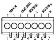
Clamp 1+ 2Sensor - Floor sensor
Clamp 3: Pilot wire (connected to L for
setback temperature)
Clamp 4: Heating L
Clamp 5: L
Clamp 6: Heating N
Clamp 7: N