
CVB 88320 - Dørtelefon GEV - Gratis brugsanvisning og manual
Find enhedens vejledning gratis CVB 88320 GEV i PDF-format.

Brugerspørgsmål om CVB 88320 GEV
0 spørgsmål om dette apparat. Besvar dem du kender, eller stil dit eget.
Stil et nyt spørgsmål om dette apparat
Download vejledningen til din Dørtelefon i PDF-format gratis! Find din vejledning CVB 88320 - GEV og tag din elektroniske enhed tilbage i hånden. På denne side er alle dokumenter nødvendige for brugen af din enhed offentliggjort. CVB 88320 af mærket GEV.
BRUGSANVISNING CVB 88320 GEV
GEV

Gutkes GmbH
Rehkamp 13
30853 Langenhagen
Germany
www.gev.de
service@gev.de
Hotline: +49 (0)180/59 58 555
Max. 14 Ct./Min aus dem deutschen Festnetz.
Mobil max. 42 Ct./Min.
International calls may vary.

03/2014 UW
A
B
1
2
C
1
2
4
3
5
D
E
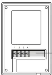
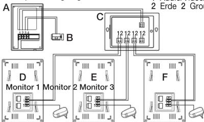
Schaltplan/Wiring diagram
1 Audio/Video/Strom 1 Audio/Video/Power
2 Erde 2 Ground wire
flowchart
graph TD
    A["Monitor 1"] --> B["2 Erde 2 Group"]
    B --> C["Group Connection"]
    C --> D["Monitor 2"]
    D --> E["2 Monitor 3"]
    E --> F["Group Connection"]
    F --> G["Monitor 3"]
    G --> H["2 Erde 2 Group"]
    H --> I["Group Connection"]
    I --> J["Monitor 3"]
    J --> K["2 Erde 2 Group"]
Distributor CVB 88528
A Außeneinheit/Outdoor unit
B Türöffner/Electric lock
C Verteiler/Distributor
D Zusätzliche Inneneinheit/
Add. indoor unit
E Zusätzliche Inneneinheit/Add, indoor unit
F Zusätzliche Inneneinheit/
Add. indoor unit
3
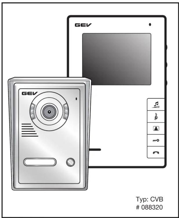
1-Familienhaus Video-Türsprechanlage CVB 88320
(2-Draht-Technik)
Lieferumfang
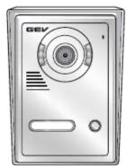
1 Außeneinheit mit Regenschutzgehäuse
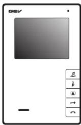
1 Inneneinheit
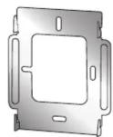
- Wandhalterungen für Inneneinheit
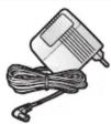
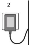
1 Netzteil
- Außeneinheit
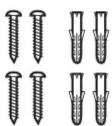
1 Abschließlich Schrauben
- Viernoliges Adanterkabel
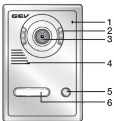
Tastenbelegung/Bedienungselemente
Außeneinheit (Abb. A)
1 Mikrofon
-
Infrarotleuchte
-
Infarotioscento
- Kamero
3 Kamera 4
4 Lautsprecher
5 Klingelknopf
6 Namensschild
7 Anschlussklemmen
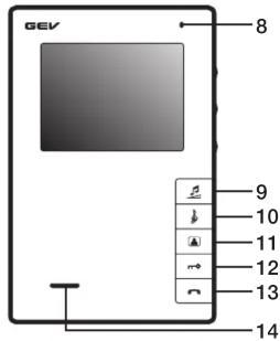
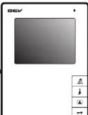
Inneneinheit (Monitor) (Abb. A)
8 Mikrofon
-
Lautstärkeregler
-
Klingeltonwähltaste
11 Überwachungsfunktion an/aus
- Türöffpertaste
12 Turonmertaste 13 Seeschlaste
13 Sprechtaste
14 Lautsprecher
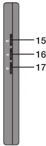
15 Helligkeitsregler
16 Kontrastregler
- Sprechlautstärke
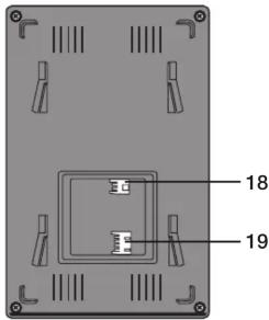
Anschlusselemente
18 Spannungsanschluss für externes Netzteil
19 Leitungsanschluss
Leistungsmerkmale
1-Familienhaus Video-Türsprechanlage mit 16 polyphonen Klingeltönen und 102 mm Bildschirmdiagonale. Spritzwassergeschütze Außeneinheit mit Regenschutzgehäuse und automatischer Lautstärkekontrolle, Türöffner- und Kameraüberwachungsfunktion mit Infrarotlicht. Manuell einstellbare Gesprächslautstärke, Klingellaustärke, Helligkeit und Kontrast.
Sicherheitshinweise
Bei Schäden, die durch Nichtbeachtung dieser Bedienungsanleitung verursacht werden erwartet.
werden, erlischt der Garantieanspruch! Für Folgeschäden übernehmen wir keine Haftung! Bei Sach- oder Personenschäden, die durch unsachgemäße Handhabung oder Nichtbeachtung der Sicherheitshinweise verursacht werden, übernehmen wir keine Haftung. In solchen Fällen erlischt jeder Gewährleistungs- und Garantieanspruch. Aus Sicherheits- und Zulassungsgründen ist das eigenmächtige Umbauen und/oder Verändern des Gerätes nicht gestattet.
Montage
Wenn Sie sich bei Montage, Anschluss und Installation nicht sicher sind, bzw. Zweifel über die Funktionsweise bestehen, so nehmen Sie die Montage /Installation nicht selber vor, sondern wenden sich an eine entsprechende Fachkraft.
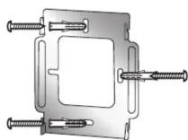
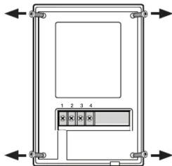
Installation der Inneneinheit (Monitor)
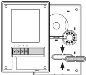
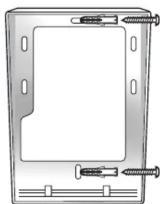
Befestigen Sie die Wandhalterung mit den drei mitgelieferten Schrauben an die von Ihnen vorgesehene Stelle (Abb. B1). Stellen sie sicher, dass bevor Sie die Innenstation in die nun montierte Wandhalterung einhängen, alle Kabelverbindungen bereits verdrahtet sind. Stecken Sie dann das Kabel des Netzteils in den Monitor und dann dass Netzteil in die Steckdose (Abb. B2).
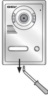
Installation der Außeneinheit
Beschriftung des Namensschilds
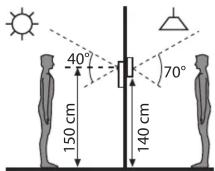
Entfernen des Regenschutzgehäuses: Hierzu lösen Sie zunächst die Schraube an der Unterseite (Abb. C1). Anschließend lösen Sie die vier Schrauben auf der nun freiliegenden Rückseite der Kameraeinheit (Abb. C2). Jetzt können Sie die Deckplatte abheben. Sie haben jetzt die Möglichkeit das Namensschild zu entnehmen und zu beschriften (Abb. C3). Hierzu lösen Sie die Rückseite des Namensschilds mit einem geeigneten Schraubendreher vorsichtig ab. Anschließend wieder einrasten. Schrauben Sie das Gerät wieder zusammen. Wir empfehlen eine Montagehöhe für die Außeneinheit von ca. 140 cm bis 170 cm, diese kann aber je nach Ihren eigenen Gegebenheiten variieren (Abb. C4). Achten Sie darauf, dass Sie das Gerät nicht unmittelbar der Witterung aussetzen (z. B. direktem Regen). Vermeiden Sie eine Platzierung in direktem Sonnenlicht. Stellen Sie vor der endgültigen Montage sicher, dass die Innen- und die Außeneinheit korrekt verdrahtet wurden und funktionsfähig sind. Beachten Sie die max. Entfernungsangaben zwischen den einzelnen Elementen (siehe Abschnitt „Anschluss“). Um die Außeneinheit an die Wand zu installieren, schrauben Sie zunächst das Regenschutzgehäuse wie in Abb. C5 an die Wand. Bevor Sie die Wandmontage abschließen, schließen Sie zunächst die Kabel an der Außeneinheit entsprechend des Schaltplans (Abb. D) an (bzw. siehe Abschnitt „Anschluss“). Nun hängen Sie das Kameramodul in das Regenschutzgehäuse und befestigen Sie das Gerät wieder mit der Schraube auf der Unterseite.
Anschluss
Im Lieferumfang der Video-Türsprechanlage CVB 88320 befindet sich eine zweipolige Adapterleitung, die Sie mit Ihrer vorhandenen Installationsleitung (nicht im Lieferumfang) verbinden. Für Entfernungen zwischen Innen- und Außeneinheit bis 50 m verwenden Sie 2 x 0,5 mm² Kabel. Verbinden Sie die Adapterleitung mit dem Monitor (Abb. A18).
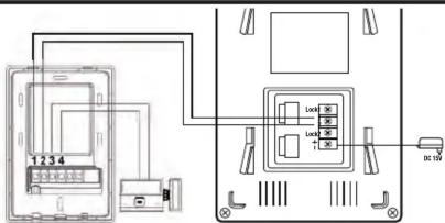
Anschluss der Außeneinheit (Abb. D)
Verbinden Sie die Klemmen der Außeneinheit 1 und 2 mit den korrespondierenden Leitungen 1 und 2 der Inneneinheit (siehe Schaltplan Abb. D). Verbinden der Außeneinheit mit einem Türöffner (nicht im Lieferumfang) (Abb. D). Verbinden Sie hierzu die Klemmen 3 und 4 der Außeneinheit mit dem Türöffner. Schließen Sie zur Spannungsversorgung den Monitor an das dafür vorgesehene Ende des Netzteils an die mit „+“ und „-“ gekennzeichneten Klemmen Falls Sie einen Türöffner benötigen, empfehlen wir Ihnen aus unserem Sortiment Best.-Nr.: 007680/007642 (110 mm) oder 007697/007666 (250 mm).
Inbetriebnahme/Bedienung
Durch Druck auf den Klingelknopf (Abb. A5) wird an den Inneneinheiten ein akustisches Signal ausgelöst und der Monitor schaltet sich ein. Sie können mit dem Gast sprechen, indem Sie kurz auf die Sprechtaste (Abb. A13) drücken. Die Gesprächsdauer beträgt ca. 120 Sek. Sie können das Gespräch jederzeit durch nochmaligen Druck der Sprechtaste beenden. Ohne Benutzeraktivität wechselt das Panel nach ca. 40 Sek. automatisch in den Stand-By Modus. Drücken Sie die Türöffnertaste (Abb. A12) um die Tür zu öffnen. Mit Druck auf die Monitortaste (Abb. A11) können Sie jederzeit den von der Kamera erfassten Bereich überwachen. Nach ca. 40 Sek. schaltet sich das System wieder in den Stand-By Modus. Sie können die Helligkeit (Abb. A15) und den Kontrast (Abb. A16) des Bildschirms anpassen, in dem Sie an den Drehreglern justieren. Zwischen den insgesamt 16 polyphonischen Klingeltönen wählen Sie durch Druck auf Melodietaste (Abb. A10). Gleiches gilt für die Lautstärkeregeling (Abb. A9). Bestätigen Sie Ihre Eingaben jeweils mit einem Druck auf die Sprechtaste (Abb. A13).
Erweiterungsmöglichkeiten
Sie können in diesem System bis zu max. 3 Inneneinheiten betreiben (Best.-Nr.: 088481). Für den Anschluss von 2 oder 3 Inneneinheiten ist ein Distributor notwendig (Best.-Nr.: 088528) (Abb. F).
Häufige Fehlerursachen
| Problem | Mögliche Ursache |
| Monitor ohne Funktion | Strom richtig angeschlossen?Stecker eingesteckt? |
| Monitor zeigt Funktion, aber kein Bild | Ist das Kabel zwischen Kamera und Monitor korrekt angeschlossen?Polarität der angeschlossenen Kabel zwischen Kamera und Monitor prüfen |
| Das Bild ist zu hell oder zu dunkel | Helligkeit anpassen (siehe Anleitung) |
| Klingelsignal zu laut/leise | Lautstärke anpassen |
Technische Daten CVB 88320
| Inneneinheit (88481) | Spezifikationen |
| Betriebsspannung | DC 15 V ^m |
| Leistungsaufnahme | Betrieb max. 10 W |
| Stand-By | < 0,1 W |
| Monitor | TFT-LED 102 mm Bildschirmdiagonale |
| Auflösung | 320 x 240 Pixel |
| Betriebstemperatur | -5 °C bis 40 °C |
| Montageart | Aufputz |
| Abmessungen | ca. B 125 x H 190 x T 26 mm |
Außeneinheit (8832001) Spezifikationen
| Kamera | CCD Sensor > 420 TV Zeilen |
| Betriebstemperatur | -20 °C bis +50 °C |
| Montageart | Aufputz |
| Türöffner | max. 12 V/ 1,0 A |
| Abmessungen | ca. B 95 x H 142 x T 38 mm |
Netzteil
Eingangsspannung
Ausgangsspannung
Nennstrom
Spezifikationen
230 V \~, 50 Hz
DC 15 V=
1.2 A
Max. Entfernung zwischen Innen- und Ausseneinheit bis 50 m ø 2 x 0,5 mm ^2 .
Technische und optische Änderungen ohne Ankündigung vorbehalten.
1 Apartment Video Door Entry System CVB 88320
(2-Wire installation)
In this Set
1 Rain cover
1 Indoor unit
1 Wall mount bracket for internal unit
1 External power supplies
1 Outdoor unit
Screws
1 Four-pole adapter cable
Key assignment/Controls
Outdoor unit (Fig. A)
1 Microphone
2 Infrared light
-
Camera
-
Speaker
5 Doorbell buttons
6 Doorbelb bat 6 Nomenplates
6 Nameplates
/ Terminal
Indoor Unit (Monitor) (Fig. A)
8 Microphone
9 Volume adjustment
10 Ringtone selection button
-
Monitoring function on/off
-
Door opener button
12 Door opener button 13 Tolly button
13 Talk button
14 Speaker
15 Brightness button
16 Contrast contro
17 Speaker volume
Connection elements
18 Connection terminal for external power supply
19 Wire connector
Features
2-Family house video door intercom with 16 polyphonic ringtones and 102 mm diagonal screen size. Splashproof outdoor unit with rain cover and automatic loudness control, door opener and camera monitoring function with infrared light. Manually adjustable call, ringer, brightness and contrast volume.
Safety instructions
Under no circumstances does the warranty cover damage resulting from failure to observe these instructions. Nor do we accept liability for any indirect damage. Similarly, we can accept no liability for any material damage or bodily injury caused by mishandling or failure to observe the safety instructions. In these cases, no warranty claim may be made. In addition, for safety and compliance reasons, you are not authorised to dismantle or alter the device in any way.
Installation
If in any doubt, rather than mounting, connecting or installing the equipment yourself, contact a qualified technician.
Installation of the indoor unit (Monitor)
Attach the wall mount bracket with the three provided screws to your intended site (Fig. B1). Make sure that all cable connections are already wired before
installing the indoor unit in the now mounted wall bracket. Then plug the cable of the power supply into the monitor and then the AC adapter into the wall outlet (Fig. B2).
Installation of the outdoor unit
Lettering of the nameplate
Remove the rain cover: First loosen the screw on the bottom side (Fig. C1). Then loosen the four screws on the now exposed backside of the camera unit (Fig. C2). Now you can lift the cover. You now have the ability to remove the nameplate and to label it (Fig. C3). Loosen carefully the rear of the nameplate with an appropriate screwdriver. Then snap back into place. Screw the device back together. We recommend a mounting height of the outdoor unit of about 140 cm to 170 cm but this can vary depending on your own circumstances (Fig. C4). Make sure that you do not expose the unit directly to the weather (e.g. direct rain). Avoid placing it in direct sunlight. Before the final assembly, ensure that the indoor and the outdoor unit are wired correctly and are operational. Please also note the maximum distance between the individual elements (see point „Connection“).
To install the outdoor unit on the wall, first screw the rain cover as shown in Fig. C5 onto the wall. Before finishing the wall mounting, connect the cables to the outdoor unit according to the wiring diagram (or see section „Connection“). Now hook the camera module in the rain cover and attach the device with the screw on the bottom.
Connection
Included with the video door entry kit CVB 88320 is a two-pin adapter cable that you need to connect with your existing installation cable (not supplied). For distances between indoor and outdoor unit up to 50 m use at least 2 x 0, 5 mm ^2 cable. Connect the adapter cable to the monitor (Fig. A18).
Connecting the outdoor unit (Fig. D). Connect the terminals of the outdoor unit 1 and 2 with the corresponding lines 1 and 2 of the indoor unit (see wiring diagram). Connect the outdoor unit with a door opener (not supplied) (Fig. D). Connect terminals 3 and 4 of the outdoor unit with the door opener. Connect the power supply to the monitor's designated end of the power supply with the „+” and “-” marked terminals. If you need a door opener, we recommend from our range Order no. 007680/007642 (110 mm) or 007697/007666 (250 mm).
Activation/Operation
By pressing the call button (Fig. A5), an acoustic signal is triggered at the indoor units and the monitors turn on. You can speak with the guest by briefly pressing on the talk button (Fig. A13). The talking time is approximately 120 seconds. You can end the conversation at any time by pressing again the talk button. Without user activity the panel automatically switches to stand-by mode after about 40 seconds. Press the door opener button (Fig. A12) in order to open the door. By pressing the monitoring function (Fig. A11) you can monitor at any time the area covered by the camera. After about 40 seconds the system switches back in stand-by mode. You can adjust the brightness (Fig. A15) and contrast (Fig. A16) of the screen, by adjusting the control dial. Between the 16 polyphonic ringtones you select by
pressing the ringtone selection button (Fig. A10). The same applies for the volume control (Fig. A9). Confirm your entries each with a press of the talk button (Fig. A13).
Expansion options
You can operate in this system up to 3 indoor units (order no.: 088481). Furthermore you need a distributor (order no.: 088528) (Fig. F).
Other Notes
Do not install the indoor units where they are exposed to high temperatures and humidity or in the vicinity of TV sets. Do not touch the sensor
buttons with wet hands. To clean the monitor or the camera, do not use cleaning agents. Simply use a damp cloth. Do not install the camera and the indoor unit in occurrence of direct light. Do not install near electronic devices (TV, Computer, telephones), as this may lead to disturbances of the system.
Recycling instructions
This device may not be disposed of with unsorted household waste. Owners of old devices are required by law to dispose of this device correctly. Contact your town council for further information.
Troubleshooting
Problem Check point
| No power(no picture on monitor) | • Is the power supply connected correctly? |
| Power is on, but no picture on the monitor | • Is the cable firmly connected between the monitor and the camera?• Is the polarity of wires correct between the outdoor camera unit and indoor monitor unit? |
The picture is too dark or white • Adjust brightness control
Chime sound is too low • Adjust the volume control
Technical information CVB 88320
| Indoor unit (88481) | Specifications |
| Supply voltage | DC 15 V ^** |
| Rated power | operation max 10 W |
| Stand-by | < 0.1 W |
| Monitor | TFT-LED 102 mm diagonal screen size |
| Resolution | 320 x 240 pixels |
| Operating temperature | -5 °C to 40 °C |
| Mounting method | surface mounted |
| Dimensions | approx. W 125 x H 190 x D 26 mm |
Power Supply (for each indoor monitor)
| Input voltage 230 V~, 50 Hz | |
| Output voltage | DC 15 Vm |
| Rated current | 1.2 A |
Outdoor Unit (8832001)
| Camera | CCD sensor > 420 TV lines |
| Operating temperature | -20 °C to +50 °C |
| Mounting method | surface mounted |
| Door opener | max. 12 V/1.0 A |
| Dimensions | approx. W 85 x H 142 x D 38 mm |
Specifications
Technical and design features may be subject to change without notice.