
Flex System x240 - Server IBM - Gratis brugsanvisning og manual
Find enhedens vejledning gratis Flex System x240 IBM i PDF-format.


Brugerspørgsmål om Flex System x240 IBM
0 spørgsmål om dette apparat. Besvar dem du kender, eller stil dit eget.
Stil et nyt spørgsmål om dette apparat
Download vejledningen til din Server i PDF-format gratis! Find din vejledning Flex System x240 - IBM og tag din elektroniske enhed tilbage i hånden. På denne side er alle dokumenter nødvendige for brugen af din enhed offentliggjort. Flex System x240 af mærket IBM.
BRUGSANVISNING Flex System x240 IBM
IBM®

Redbooks
IBM Flex System x240 Compute Node (E5-2600)
IBM Redbooks Product Guide
The IBM Flex System™ x240 Compute Node is a high-performance server that offers outstanding performance for virtualization with new levels of CPU performance and memory capacity, and flexible configuration options. The x240 Compute Node is an efficient server designed to run a broad range of workloads, armed with advanced management capabilities allowing you to manage your physical and virtual IT resources from a single-pane of glass.
Suggested use: database, virtualization, enterprise applications, collaboration/email, streaming media, web, HPC, Microsoft RemoteFX, and cloud applications.
Note: This Product Guide describes the models of the x240 Compute Node with Intel Xeon E5-2600 processors. For models with the Intel Xeon E5-2600 v2 processors, see http://www.redbooks.ibm.com/abstracts/tips1090.html?Open
Figure 1 shows the IBM Flex System x240 Compute Node.

natural_image
Front view of a white server rack unit with ventilation grilles and drive bays (no visible text or labels)Key features
The IBM Flex System x240 Compute Node is a high-availability, scalable compute node optimized to support the next-generation microprocessor technology and is ideally suited for medium and large businesses. This section describes the key features of the server.
Scalability and performance
The x240 offers numerous features to boost performance, improve scalability, and reduce costs:
- The Intel Xeon Processor E5-2600 product family improves productivity by offering superior system performance with up to 8-core processors and up to 3.3 GHz core speeds depending on the CPU's number of cores, up to 20 MB of L3 cache, and QPI interconnect links of up to 8 GT/s.
- The Intel Xeon Processor E5-2600 provides up to 80% performance boost over the previous generation, the Intel Xeon Processor 5600 (Westmere EP).
- Up to two processors, 16 cores, and 32 threads maximize the concurrent execution of multi-threaded applications.
- Intelligent and adaptive system performance with Intel Turbo Boost Technology 2.0 allows CPU cores to run at maximum speeds during peak workloads by temporarily going beyond processor TDP.
- Intel Hyper-Threading Technology boosts performance for multi-threaded applications by enabling simultaneous multi-threading within each processor core, up to two threads per core.
- Intel Virtualization Technology integrates hardware-level virtualization hooks that allow operating system vendors to better utilize the hardware for virtualization workloads.
- Intel Advanced Vector Extensions (AVT) significantly improve floating point performance for compute-intensive technical and scientific applications compared with Intel Xeon 5600 series processors.
- Up to 24 DDR3 ECC memory RDIMMs provide speeds up to 1600 MHz and a memory capacity of up to 384 GB. Load-reduced DIMMs (LRDIMMs) are supported with a maximum capacity of 768 GB.
- The theoretical maximum memory bandwidth of the Intel Xeon processor E5 family is 51.6 GBps, which is 60% more than in the previous generation of Intel Xeon processors.
- The use of solid-state drives (SSDs) instead of or along with traditional spinning drives (HDDs) can significantly improve I/O performance. An SSD can support up to 100 times more I/O operations per second (IOPS) than a typical HDD.
Availability and serviceability
The x240 provides many features to simplify serviceability and increase system uptime:
- Chipkill, memory mirroring and memory rank sparing for redundancy in the event of a non-correctable memory failure.
- Tool-less cover removal provides easy access to upgrades and serviceable parts, such as CPU, memory, and adapter cards.
- Hot-swap drives supporting integrated RAID 1 redundancy for data protection and greater system uptime.
- A light path diagnostics panel and individual light path LEDs to quickly lead the technician to failed (or failing) components. This simplifies servicing, speeds up problem resolution, and helps improve system availability.
- Predictive Failure Analysis (PFA), which detects when system components (such as processors, memory, and hard disk drives) operate outside of standard thresholds and generates pro-active alerts in advance of possible failure, therefore increasing uptime.
- Solid-state drives (SSDs), which offer significantly better reliability than traditional mechanical HDDs for greater uptime.
- Built-in Integrated Management Module II (IMM2) continuously monitors system parameters, triggers alerts, and performs recovering actions in case of failures to minimize downtime.
- Built-in diagnostics using Dynamic Systems Analysis (DSA) Preboot speeds up troubleshooting tasks to reduce service time.
- Three-year customer replaceable unit and onsite limited warranty, next business day 9x5. Optional service upgrades are available.
Manageability and security
Powerful systems management features simplify local and remote management of the x240:
- The x240 includes an Integrated Management Module II (IMM2) to monitor server availability and perform remote management.
- Integrated industry-standard Unified Extensible Firmware Interface (UEFI) enables improved setup, configuration, and updates, and simplifies error handling.
- Integrated Trusted Platform Module (TDM) 1.2 support enabling advanced countergraphic functionality
Energy efficiency
The x240 offers the following energy-efficiency features to save energy, reduce operational costs, increase energy availability, and contribute to the green environment:
- Component-sharing design of the IBM Flex System chassis provides ultimate power and cooling savings.
- The Intel Xeon processor E5-2600 product family offers significantly better performance over the previous generation while fitting into the same thermal design power (TDP) limits.
- Intel Intelligent Power Capability powers individual processor elements on and off as needed, to reduce power draw.
- Low-voltage Intel Xeon processors draw less energy to satisfy demands of power and thermally constrained data centers and telecommunication environments.
- Low-voltage 1.35 V DDR3 memory RDIMMs consume 15% less energy than 1.5 V DDR3 RDIMMs.
- Solid state drives (SSDs) consume as much as 80% less power than traditional spinning 2.5-inch HDDs.
- The x240 uses hexagonal ventilation holes, a part of IBM Calibrated Vectored Cooling™ technology. Hexagonal holes can be grouped more densely than round holes, providing more efficient airflow through the system.
Locations of key components and connectors
Figure 2 shows the front of the server.

Figure 3 shows the locations of key components inside the server.

Figure 3. Inside view of the IBM Flex System x240 Compute Node
Standard specifications
The following table lists the standard specifications.
Table 1. Standard specifications (part 1)
| Components | Specification |
| Models | 8737-x1x and 8737-x2x (x-config)8737-15X and 7863-10X (e-config) |
| Form factor | Standard-width compute node. |
Table 1. Standard specifications (part 2)
| Components | Specification |
| Memory protection | ECC, Chipkill (for x4-based memory DIMMs), memory mirroring, and memory rank sparing. |
| Disk drive bays | Two 2.5" hot-swap SAS/SATA drive bays supporting SAS, SATA, and SSD drives. Optional support for up to eight 1.8" SSDs. Up to 12 additional 2.5-inch drive bays with the optional Storage Expansion Node. |
| Maximum internal storage | With two 2.5" hot-swap drives: Up to 2 TB with 1 TB 2.5" NL SAS HDDs, or up to 2.4 TB with 1.2 TB 2.5" SAS HDDs, or up to 2 TB with 1 TB 2.5" SATA HDDs, or up to 3.2 TB with 1.6 TB 2.5" SATA SSDs. An intermix of SAS and SATA HDDs and SSDs is supported. Alternatively, with 1.8" SSDs and ServeRAID M5115 RAID adapter, up to 4 TB with eight 512 GB 1.8" SSDs. Additional storage available with an attached Flex System Storage Expansion Node. |
| RAID support | RAID 0 and 1 with integrated LSI SAS2004 controller. Optional ServeRAID M5115 RAID controller with RAID 0, 1, 10, 5, 50 support and 1 GB cache. Supports up to eight 1.8" SSD with expansion kits. Optional flash-backup for cache, RAID 6/60, SSD performance enabler. |
| Network interfaces | x2x models: Two 10 Gb Ethernet ports with Embedded 10Gb Virtual Fabric Ethernet LAN-on-motherboard (LOM) controller; Emulex BE3 based.x1x models: None standard; optional 1Gb or 10Gb Ethernet adapters. |
| PCI Expansion slots | Two I/O connectors for adapters. PCI Express 3.0 x16 interface. Includes an Expansion Connector (PCIe 3.0 x16) to connect an expansion node such as the PCIe Expansion Node. PCIe Expansion Node supports two full-height PCIe adapters, two low-profile PCIe adapters and two Flex System I/O adapters. |
| Ports | USB ports: One external. Two internal for embedded hypervisor with optional USB Enablement Kit. Console breakout cable port providing local KVM and serial ports (cable standard with chassis; additional cables optional). |
| Systems management | UEFI, IBM Integrated Management Module 2 (IMM2) with Renesas SH7757 controller, Predictive Failure Analysis, light path diagnostics panel, automatic server restart, remote presence. Support for IBM Flex System Manager, IBM Systems Director and Active Energy Manager, IBM ServerGuide. |
| Security features | Power-on password, administrator's password, Trusted Platform Module 1.2. |
| Video | Matrox G200eR2 video core with 16 MB video memory integrated into the IMM2. Maximum resolution is 1600x1200 at 75 Hz with 16 M colors. |
Standard models
Note: This Product Guide describes the models of the x240 Compute Node with Intel Xeon E5-2600 processors. For models with the Intel Xeon E5-2600 v2 processors, see http://www.redbooks.ibm.com/abstracts/tips1090.html?Open
Table 2. Standard models
| Model | Intel Xeon Processor (2 maximum)* | Memory (max 708 GB) | Disk adapter | Disk beys† | Disk | 10 GbE Embedded Virtual Fabric‡ | I/O slot (used/max) |
| 8737-A1x | 1x E5-2630L 6C 2.0GHz 15MB 1333MHz 60W | 2x 4 GB | LSI SAS2004 | 2x 2.5-inch hot-swap | Open | No | 0 / 2 |
| 8737-D2x | 1x E5-2609 4C 2.40GHz 10MB 1066MHz 80W | 2x 4 GB | LSI SAS2004 | 2x 2.5-inch hot-swap | Open | Standard | 1 / 2‡ |
| 8737-F2x | 1x E5-2620 6C 2.0GHz 15MB 1333MHz 95W | 2x 4 GB | LSI SAS2004 | 2x 2.5-inch hot-swap | Open | Standard | 1 / 2‡ |
| 8737-G2x | 1x E5-2630 6C 2.3GHz 15MB 1333MHz 95W | 2x 4 GB | LSI SAS2004 | 2x 2.5-inch hot-swap | Open | Standard | 1 / 2‡ |
| 8737-H1x | 1x E5-2640 6C 2.5GHz 15MB 1333MHz 95W | 2x 4 GB | LSI SAS2004 | 2x 2.5-inch hot-swap | Open | No | 0 / 2 |
| 8737-H2x | 1x E5-2640 6C 2.5GHz 15MB 1333MHz 95W | 2x 4 GB | LSI SAS2004 | 2x 2.5-inch hot-swap | Open | Standard | 1 / 2‡ |
| 8737-J1x | 1x E5-2670 8C 2.6GHz 20MB 1600MHz 115W | 2x 4 GB | LSI SAS2004 | 2x 2.5-inch hot-swap | Open | No | 0 / 2 |
| 8737-L2x | 1x E5-2660 8C 2.2GHz 20MB 1600MHz 95W | 2x 4 GB | LSI SAS2004 | 2x 2.5-inch hot-swap | Open | Standard | 1 / 2‡ |
| 8737-M1x | 1x E5-2680 8C 2.7GHz 20MB 1600MHz 130W | 2x 4 GB | LSI SAS2004 | 2x 2.5-inch hot-swap | Open | No | 0 / 2 |
| 8737-M2x | 1x E5-2680 8C 2.7GHz 20MB 1600MHz 130W | 2x 4 GB | LSI SAS2004 | 2x 2.5-inch hot-swap | Open | Standard | 1 / 2‡ |
| 8737-N2x | 1x E5-2643 4C 3.3GHz 10MB 1600MHz 130W | 2x 4 GB | LSI SAS2004 | 2x 2.5-inch hot-swap | Open | Standard | 1 / 2‡ |
| 8737-Q2x | 1x E5-2667 6C 2.9GHz 15MB 1600MHz 130W | 2x 4 GB | LSI SAS2004 | 2x 2.5-inch hot-swap | Open | Standard | 1 / 2‡ |
Windows Storage Server 2012 is available via the IBM Reseller Option Kit (ROK) program using part number 00Y6302. Model HBx does not include drives giving you maximum flexibility when it comes to selecting drives, either SAS or SATA disk drives or high-performance solid-state drives.
Chassis support
The x240 is supported in the IBM Flex System Enterprise Chassis.
Up to 14 x240 Compute Nodes can be installed in the chassis, however, the actual number that can be installed in a chassis depends on these factors:
The TDP power rating for the processors that are installed in the x240
The number of power supplies installed in the chassis
The capacity of the power supplies installed (2100 W or 2500 W)
The chassis power redundancy policy used (N+1 or N+N)
The following table provides guidelines about what number of x240 Compute Nodes can be installed. For more guidance, use the Power Configurator, found at the following website: http://ibm.com/systems/bladecenter/resources/powerconfig.html
In the table:
Green = No restriction to the number of x240 Compute Nodes that are installable
Yellow = Some bays must be left empty in the chassis
Table 3. Maximum number of x240 Compute Nodes installable based on power supplies installed and power redundancy policy used
2100 W power supplies installed 2500 W power supplies installed
| x240 TDP rating | N+1, N=56 powersupplies | N+1, N=45 powersupplies | N+1, N=35 powersupplies | N+N, N=36 powersupplies | N+1, N=56 powersupplies | N+1, N=45 powersupplies | N+1, N=34 powersupplies | N+N, N=36 powersupplies |
| 60 W 14 14 | 14 14 14 14 | 14 14 14 14 | ||||||
| 70 W 14 14 | 13 14 14 14 | 14 14 14 | ||||||
| 80 W 14 14 | 13 13 14 14 | 14 14 14 | ||||||
| 95 W 14 14 | 12 12 14 14 | 14 14 14 | ||||||
| 115 W 14 | 14 11 12 14 | 14 14 14 | ||||||
| 130 W 14 | 14 11 11 14 | 14 13 14 | ||||||
| 135 W 14 | 14 10 11 14 | 14 13 14 |
Processor options
The x240 supports the processor options listed in the following table. The server supports one or two processors. The table also shows which server models have each processor standard. If no corresponding where used model for a particular processor is listed, then this processor is available only through Configure to Order (CTO).
Table 4. Processor options
| Part number | Feature code** | Intel Xeon processor description | Models where used |
| 81Y5 180 | A1CQ / A1D1 | Intel Xeon E5-2603 4C 1.8GHz 10MB 1066MHz 80W | - |
| 81Y5 182 | A1CS / A1D3 | Intel Xeon E5-2609 4C 2.40GHz 10MB 1066MHz 80W | D2x |
| 81Y5 183 | A1CT / A1D4 | Intel Xeon E5-2620 6C 2.0GHz 15MB 1333MHz 95W | F2x |
| 81Y5 184 | A1CU / A1D5 | Intel Xeon E5-2630 6C 2.3GHz 15MB 1333MHz 95W | G2x |
| 81Y5 206 | A1ER / A1DD | Intel Xeon E5-2630L 6C 2.0GHz 15MB 1333MHz 60W | A1x |
| 49Y8 125 | A2EP / A2EQ | Intel Xeon E5-2637 2C 3.0GHz 5MB 1600MHz 80W | - |
| 81Y5 185 | A1CV / A1D6 | Intel Xeon E5-2640 6C 2.5GHz 15MB 1333MHz 95W | H1x, H2x, HBx |
| 81Y5 190 | A1CY / A1DA | Intel Xeon E5-2643 4C 3.3GHz 10MB 1600MHz 130W | N2x |
| 95Y4 670 | A31A / A31C | Intel Xeon E5-2648L 8C 1.8GHz 20MB 1600MHz 70W | - |
| 81Y5 186 | A1CW / A1D7 | Intel Xeon E5-2650 8C 2.0GHz 20MB 1600MHz 95W | - |
| 81Y5 179 | A1ES / A1DE | Intel Xeon E5-2650L 8C 1.8GHz 20MB 1600MHz 70W | - |
| 95Y4 675 | A319 / A31B | Intel Xeon E5-2658 8C 2.1GHz 20MB 1600MHz 95W | - |
| 81Y5 187 | A1CX / A1D8 | Intel Xeon E5-2660 8C 2.2GHz 20MB 1600MHz 95W | L2x |
| 49Y8 144 | A2ET / A2EU | Intel Xeon E5-2665 8C 2.4GHz 20MB 1600MHz 115W | - |
| 81Y5 189 | A1CZ / A1DB | Intel Xeon E5-2667 6C 2.9GHz 15MB 1600MHz 130W | Q2x |
| 81Y9 418 | A1SX / A1SY | Intel Xeon E5-2670 8C 2.6GHz 20MB 1600MHz 115W | J1x |
| 81Y5 188 | A1BB / A1D9 | Intel Xeon E5-2680 8C 2.7GHz 20MB 1600MHz 130W | M1x, M2x |
Memory options
IBM DDR3 memory is compatibility tested and tuned for optimal performance and throughput. IBM memory specifications are integrated into the light path diagnostics for immediate system performance feedback and optimum system uptime. From a service and support standpoint, IBM memory automatically assumes the IBM system warranty, and IBM provides service and support worldwide.
The following table lists memory options available for the x240 server. DIMMs can be installed one at a time, but for performance reasons, install them in sets of four (one for each of the four memory channels).
Table 5. Memory options for the x240
| Part number | Feature code | Description | Models where used |
| Registered DIMM (RDIMM) modules - 1066 MHz and 1333 MHz | |||
| 49Y 1405 | 8940 | 2GB (1x2GB, 1Rx8, 1.35V) PC3L-10600 CL9 ECC DDR3 1333MHz LP RDIMM | - |
| 49Y 1406 | 8941 | 4GB (1x4GB, 1Rx4, 1.35V) PC3L-10600 CL9 ECC DDR3 1333MHz LP RDIMM | H1x, H2x, G2x, F2x, D2x, A1x |
| 49Y 1407 | 8942 | 4GB (1x4GB, 2Rx8, 1.35V) PC3L-10600 CL9 ECC DDR3 1333MHz LP RDIMM | - |
| 49Y 1397 | 8923 | 8GB (1x8GB, 2Rx4, 1.35V) PC3L-10600 CL9 ECC DDR3 1333MHz LP RDIMM | HBx |
| 49Y 1563 | A1QT | 16GB (1x16GB, 2Rx4, 1.35V) PC3L-10600 CL9 ECC DDR3 1333MHz LP RDIMM | - |
| 49Y 1400 | 8939 | 16GB (1x16GB, 4Rx4, 1.35V) PC3L-8500 CL7 ECC DDR3 1066MHz LP RDIMM | - |
| Registered DIMM (RDIMM) modules - 1600 MHz | |||
| 49Y 1559 | A28Z | 4GB (1x4GB, 1Rx4, 1.5V) PC3-12800 CL11 ECC DDR3 1600MHz LP RDIMM | R2x, Q2x, N2x, M2x, M1x, L2x, J1x |
| 90Y 3178 | A24L | 4GB (1x4GB, 2Rx8, 1.5V) PC3-12800 CL11 ECC DDR3 1600MHz LP RDIMM | - |
| 90Y 3109 | A292 | 8GB (1x8GB, 2Rx4, 1.5V) PC3-12800 CL11 ECC DDR3 1600MHz LP RDIMM | - |
| 0004968 | A2U5 | 16GB (1x16GB, 2Rx4, 1.5V) PC3-12800 CL11 ECC DDR3 1600MHz LP RDIMM | - |
| Unbuffered DIMM (UDIMM) modules | |||
| 49Y 1403 | A0QS | 2GB (1x2GB, 1Rx8, 1.35V) PC3L-10600 CL9 ECC DDR3 1333MHz LP UDIMM | - |
| 49Y 1404 | 8648 | 4GB (1x4GB, 2Rx8, 1.35V) PC3L-10600 CL9 ECC DDR3 1333MHz LP UDIMM | - |
• The maximum number of ranks supported per channel is eight.
- The maximum quantity of DIMMs that can be installed in the server depends on the number of CPUs, DIMM rank, and operating voltage, as shown in the "Max. qty supported" row in the following table. The shaded cells indicate that the DIMM type supports the maximum number of DIMMs (24 for the x240)
- All DIMMs in all CPU memory channels operate at the same speed, which is determined as the lowest value of:
• Memory speed supported by specific CPU
- Lowest maximum operating speed for the selected memory configuration that depends on rated speed, as shown under the "Max. operating speed" section in the following table. The shaded cells indicate that the speed indicated is the maximum that the DIMM allows.
The following tables (Part 1 and Part 2) shows the maximum memory speeds that are achievable based on the installed DIMMs and the number of DIMMs per channel. The tables also show maximum memory capacity at any speed supported by the DIMM and maximum memory capacity at rated DIMM speed. In the tables, cells highlighted with a grey background indicate when the specific combination of DIMM voltage and number of DIMMs per channel still allows the DIMMs to operate at rated speed.
Table 6. Maximum memory speeds (Part 1 - UDIMMs, LRDIMMs and Quad rank RDIMMs)
| Specification | UDIMMs | LRDIMMs | RDIMMs | |||
| Rank | Dual rank | Quad rank | Quad rank | |||
| Part numbers | 49Y1404 (4 GB) | 49Y1567 (16 GB)90Y3105 (32 GB) | 49Y1400 (16 GB) | |||
| Rated speed | 1333 MHz | 1333 MHz | 1066 MHz | |||
| Rated voltage | 1.35 V | 1.35 V | 1.35 V | |||
| Operating voltage | 1.35 V | 1.5 V | 1.35 V | 1.5 V | 1.35 V | 1.5 V |
| Maximum quantity* | 16 | 16 | 24 | 24 | 8 | 16 |
| Largest DIMM | 4 GB | 4 GB | 32 GB | 32 GB | 16 GB | 16 GB |
| Max memory capacity | 64 GB | 64 GB | 768 GB | 768 GB | 128 GB | 256 GB |
| Max memory at rated speed | 64 GB | 64 GB | N/A | 512 GB | N/A | 128 GB |
Table 6. Maximum memory speeds (Part 2 - Single and Dual rank RDIMMs)
| Specification | RDIMMs | |||||
| Rank | Single rank | Dual rank | ||||
| Part numbers | 49Y1405 (2GB)49Y1406 (4GB) | 49Y1559(4GB) | 49Y1407 (4GB)49Y1397 (8GB)49Y1563 (16GB) | 90Y3178 (4GB)90Y3109 (8GB)00D4968(16GB) | ||
| Rated speed | 1333 MHz | 1600 MHz | 1333 MHz | 1600 MHz | ||
| Rated voltage | 1.35 V | 1.5 V | 1.35 V | 1.5 V | ||
| Operating voltage | 1.35 V | 1.5 V | 1.5 V | 1.35 V | 1.5 V | 1.5 V |
| Max quantity* | 16 | 24 | 24 | 16 | 24 | 24 |
| Largest DIMM | 4 GB | 4 GB | 4 GB | 16 GB | 16 GB | 16 GB |
| Max memory capacity | 64 GB | 96 GB | 96 GB | 256 GB | 384 GB | 384 GB |
| Max memory at rated speed | N/A | 64 GB | 64 GB | N/A | 256 GB | 256 GB |
| Maximum operating speed (MHz) | ||||||
| 1 DIMM per channel | 1333 MHz | 1333 MHz | 1600 MHz | 1333 MHz | 1333 MHz | 1600 MHz |
| 2 DIMMs per channel | 1333 MHz | 1333 MHz | 1600 MHz | 1333 MHz | 1333 MHz | 1600 MHz |
| 3 DIMMs per channel | NS** | 1066 MHz | 1066 MHz | NS** | 1066 MHz | 1066 MHz |
* The maximum quantity that is supported is shown for two processors installed. When one processor is installed,
the maximum quantity that is supported is half of that shown. ** NS = Not supported at 1.35 V. Will operate at 1.5 V instead
The following memory protection technologies are supported:
ECC
- Chipkill (for x4-based memory DIMMs -- look for "x4" in the DIMM description)
• Memory mirroring
• Memory sparing
Internal storage
The x240 server has two 2.5-inch hot-swap drive bays accessible from the front of the blade server (Figure 2). These bays connect to the integrated LSI SAS2004 6 Gbps SAS/SATA RAID-on-Chip (ROC) controller.
The integrated LSI SAS2004 ROC has the following features:
• Four-port LSI SAS2004 controller with 6 Gbps throughput per port
• PCIe x4 Gen 2 host interface
• Two SAS ports routed internally to the two hot-swap drive bays
• Supports RAID-0, RAID-1 and RAID-1E
The x240 also supports up to eight 1.8-inch drives with the addition of the ServeRAID M5115 controller and additional SSD tray hardware. These are described in the next section.
Supported drives are listed in the Internal drive options section.
ServeRAID M5115 SAS/SATA controller
The x240 supports up to eight 1.8-inch solid-state drives combined with a ServeRAID M5115 SAS/SATA controller (90Y4390). The M5115 attaches to the I/O adapter 1 connector and can be attached even if the Compute Node Fabric Connector is installed (used to route the Embedded 10Gb Virtual Fabric Adapter to bays 1 and 2, as discussed in "I/O expansion options"). The ServeRAID M5115 cannot be installed if an adapter is installed in I/O adapter slot 1.
The ServeRAID M5115 supports combinations of 2.5-inch drives and 1.8-inch solid state drives:
• Up to two 2.5-inch drives only
• Up to four 1.8-inch drives only
• Up to two 2.5-inch drives, plus up to four 1.8-inch solid state drives
• Up to eight 1.8-inch solid state drives
The ServeRAID M5115 SAS/SATA Controller (90Y4390) provides an advanced RAID controller supporting RAID 0, 1, 10, 5, 50, and optional 6 and 60. It includes 1 GB of cache, which can be backed up to Flash when attached to the supercapacitor included with the optional ServeRAID M5100 Series Enablement Kit (90Y4342).
The hardware kits have the following features:
- ServeRAID M5100 Series Enablement Kit for IBM Flex System x240 (90Y4342) enables support for up to two 2.5" HDDs or SSDs in the hol-swap bays in the front of the server. It includes a CacheVault unit, which enables MegaRAID CacheVault flash cache protection. This enablement kit replaces the standard two-bay backplane (which is attached via the planar to an onboard controller) with a new backplane that attaches to an included flexible cable to the M5115 controller. It also includes an air baffle, which also serves as an attachment for the CacheVault unit.
MegaRAID CacheVault flash cache protection uses NAND flash memory powered by a supercapacitor to protect data stored in the controller cache. This module eliminates the need for a lithium-ion battery commonly used to protect DRAM cache memory on PCI RAID controllers. To avoid the possibility of data loss or corruption during a power or server failure, CacheVault technology transfers the contents of the DRAM cache to NAND flash using power from the supercapacitor. After the power is restored to the RAID controller, the saved data is transferred from the NAND flash back to the DRAM cache, which can then be flushed to disk.
Tip: The Enablement Kit is only required if 2.5-inch drives are to be used. If you plan to install four or eight 1.8-inch SSDs only, then this kit is not required.
- ServeRAID M5100 Series IBM Flex System Flash Kit for x240 (90Y4341) enables support for up to four 1.8-inch SSDs. This kit replaces the standard two-bay backplane with a four-bay SSD backplane that attaches to an included flex cable to the M5115 controller. Because only SSDs are supported, a CacheVault unit is not required, and therefore this kit does not have a supercap. The use of this kit limits which 1.8-inch solid state drives can be used in the x240 as listed in Table 11. Use Flash Kit v2 instead.
- ServeRAID M5100 Series IBM Flex System Flash Kit v2 for x240 (47C8808) enables support for up to four 1.8-inch SSDs. This kit replaces the standard two-bay backplane with a four-bay SSD backplane that attaches to an included flex cable to the M5115 controller. Because only SSDs are supported, a CacheVault unit is not required, and therefore this kit does not have a supercap. This v2 kit provides support for the latest high-performance SSDs.
- ServeRAID M5100 Series SSD Expansion Kit for IBM Flex System x240 (90Y4391) enables support for up to four internal 1.8-inch SSDs. This kit includes two air baffles, left and right, which can attach two 1.8-inch SSD attachment locations and Flex cables for attachment to up to four 1.8-inch SSDs.
Note: The SSD Expansion Kit cannot be installed if the USB Enablement Kit, 49Y8119, is already installed as these kits occupy the same location in the server.
The following figure shows how the ServeRAID M5115 and the Enablement Kit are installed in the server to support two 2.5-inch drives with MegaRAID CacheVault flash cache protection (row 1 of the preceding table).

Figure 4. The ServeRAID M5115 and the Enablement Kit installed
The following figure shows how the ServeRAID M5115 and Flash and SSD Expansion Kits are installed in the server to support eight 1.8-inch solid-state drives (row 4 of the preceding table).

The eight SSDs are installed in the following locations:
• Four in the front of the system in place of the two 2.5-inch drive bays
• Two in a tray above one the memory banks for CPU 1
• Two in a tray above one the memory banks for CPU2
The ServeRAID M5115 controller has the following specifications:
• Eight internal 6 Gbps SAS/SATA ports
• PCI Express 3.0 x8 host interface
• 6 Gbps throughput per port
- 800 MHz dual-core IBM PowerPC® processor with LSI SAS2208 6 Gbps RAID on Chip (ROC) controller
- Support for RAID levels 0, 1, 10, 5, 50 standard; support for RAID 6 and 60 with optional upgrade using 90Y4411
- Onboard 1 GB data cache (DDR3 running at 1333 MHz) with optional flash backup (MegaRAID CacheVault technology) as part of the Enablement Kit 90Y4342.
• Support for SAS and SATA HDDs and SSDs
- Support for intermixing SAS and SATA HDDs and SSDs; mixing different types of drives in the same array (drive group) not recommended
• Support for self-encrypting drives (SEDs) with MegaRAID SafeStore
- Optional support for SSD performance acceleration with MegaRAID FastPath and SSD caching with MegaRAID CacheCade Pro 2.0 (90Y4447)
- Support for up to 64 virtual drives, up to 128 drive groups, up to 16 virtual drives per one drive group, and up to 32 physical drives per one drive group
• Support for logical unit number (LUN) sizes up to 64 TB
- Configurable stripe size up to 1 MB
• Compliant with Disk Data Format (DDF) configuration on disk (COD)
• S.M.A.R.T. support
• MegaRAID Storage Manager management software
These features are described as follows:
• RAID 6 Upgrade (90Y4410)
Adds support for RAID 6 and RAID 60. This is a Feature on Demand license.
• Performance Upgrade (90Y4412)
The Performance Upgrade for IBM Flex System (implemented using the LSI MegaRAID FastPath software) provides high-performance I/O acceleration for SSD-based virtual drives by exploiting an extremely low-latency I/O path to increase the maximum I/O per second (IOPS) capability of the controller. This feature boosts the performance of applications with a highly random data storage access pattern, such as transactional databases. Part number 90Y4412 is a Feature on Demand license.
• SSD Caching Enabler for traditional hard drives (90Y4447)
The SSD Caching Enabler for IBM Flex System (implemented using the LSI MegaRAID CacheCade Pro 2.0) is designed to accelerate the performance of hard disk drive (HDD) arrays with only an incremental investment in solid-state drive (SSD) technology. The feature enables the SSDs to be configured as a dedicated cache to help maximize the I/O performance for transaction-intensive applications, such as databases and web serving. The feature tracks data storage access patterns and identifies the most frequently accessed data. The hot data is then automatically stored on the SSDs that are assigned as a dedicated cache pool on the ServeRAID controller. Part number 90Y4447 is a Feature on Demand license. This feature requires at least one SSD drive be installed.
Internal drive options
The 2.5" drive bays support SAS or SATA hard disk drives (HDDs) or SATA solid state drives (SSDs). The following table lists the supported 2.5' drive options.
Table 10.2.5-inch drive options for internal disk storage (Part 1)
| Part number | Feature code | Description | Maximum supported |
| 10K SAS hard disk drives | |||
| 00AD075 | A48S | IBM 1.2TB 10K 6Gbps SAS 2.5" G2HS HDD | 2 |
| 81Y9650 | A282 | IBM 900GB 10K 6Gbps SAS 2.5" SFF HS HDD | 2 |
Table 10.2.5-inch drive options for internal disk storage (Part 2)
| Part number | Feature code | Description | Maximum supported |
| 10K and 15K Self-encrypting drives (SED) | |||
| 00AD085 | A48T | IBM 1.2TB 10K 6Gbps SAS 2.5" G2HS SED | 2 |
| 81Y9662 | A3EG | IBM 900GB 10K 6Gbps SAS 2.5" SFF G2HS SED | 2 |
| 90Y8908 | A3EF | IBM 600GB 10K 6Gbps SAS 2.5" SFF G2HS SED | 2 |
| 90Y8913 | A2XF | IBM 300GB 10K 6Gbps SAS 2.5" SFF G2HS SED | 2 |
| 90Y8944 | A2ZK | IBM 146GB 15K 6Gbps SAS 2.5" SFF G2HS SED | 2 |
| NL SAS | |||
| 81Y9690 | A1P3 | IBM 1TB 7.2K 6Gbps NL SAS 2.5" SFF HS HDD | 2 |
| 90Y8953 | A2XE | IBM 500GB 7.2K 6Gbps NL SAS 2.5" SFF G2HS HDD | 2 |
| 42D0707 | 5409 | IBM 500GB 7200 6Gbps NL SAS 2.5" SFF Slim-HS HDD | 2 |
| NL SATA | |||
| 81Y9722 | A1NX | IBM 250GB 7.2K 6Gbps NL SATA 2.5" SFF HS HDD | 2 |
| 81Y9726 | A1NZ | IBM 500GB 7.2K 6Gbps NL SATA 2.5" SFF HS HDD | 2 |
| 81Y9730 | A1AV | IBM 1TB 7.2K 6Gbps NL SATA 2.5" SFF HS HDD | 2 |
| SAS-SSD Hybrid drive | |||
| 00AD102 | A4G7 | IBM 600GB 10K 6Gbps SAS 2.5" G2HS Hybrid | 2 |
| Solid-state drives - Enterprise | |||
| 41Y8341 | A4FQ | S3700 800GB SATA 2.5" MLC HS Enterprise SSD | 2 |
| 41Y8336 | A4FN | S3700 400GB SATA 2.5" MLC HS Enterprise SSD | 2 |
| 41Y8331 | A4FL | S3700 200GB SATA 2.5" MLC HS Enterprise SSD | 2 |
| 49Y6195 | A4GH | IBM 1.6TB SAS 2.5" MLC HS Enterprise SSD | 2 |
Table 10. 2.5-inch drive options for internal disk storage (Part 3)
| Part number | Feature code | Description | Maximum supported |
| Solid-state drives - Enterprise Value | |||
| 00AJ000 | A4KM | S3500 120GB SATA 2.5" MLC HS Enterprise Value SSD | 2 |
| 00AJ005 | A4KN | S3500 240GB SATA 2.5" MLC HS Enterprise Value SSD | 2 |
| 00AJ010 | A4KP | S3500 480GB SATA 2.5" MLC HS Enterprise Value SSD | 2 |
| 00AJ015 | A4KQ | S3500 800GB SATA 2.5" MLC HS Enterprise Value SSD | 2 |
| 49Y5839 | A3AS | IBM 64GB SATA 2.5" MLC HS Enterprise Value SSD | 2 |
| 49Y5844 | A3AU | IBM 512GB SATA 2.5" MLC HS Enterprise Value SSD | 2 |
| 90Y8643 | A2U3 | IBM 256GB SATA 2.5"MLC HS Enterprise Value SSD | 2 |
| 90Y8648 | A2U4 | IBM 128GB SATA 2.5"MLC HS Enterprise Value SSD | 2 |
The 1.8-inch solid state drives supported are listed in the following table. The use of 1.8-inch requires the ServeRAID M5115 SAS/SATA controller as described in the next section. Most 1.8-inch drives are not supported by Flash Kit 90Y4341. Instead use Flash Kit v2 47C8808 as described in the ServeRAID M5115 section.
Table 11. Supported 1.8-inch solid state drives
| Part number | Feature code | Description | Supports Flash Kit 90Y4341 | Supports Flash Kit v2 47C8808 | Max supp't |
| Enterprise SSDs | |||||
| 43W7726 | 5428 | IBM 50GB SATA 1.8" MLC SSD | Yes | Yes | 8 |
| 43W7746 | 5420 | IBM 200GB SATA 1.8" MLC SSD | Yes | Yes | 8 |
| 49Y6119 | A3AN | IBM 200GB SATA 1.8" MLC Enterprise SSD | No | Yes | 8 |
| 49Y6124 | A3AP | IBM 400GB SATA 1.8" MLC Enterprise SSD | No | Yes | 8 |
| 00W1120 | A3NO | IBM 100GB SATA 1.8" MLC Enterprise SSD | No | Yes | 8 |
IBM Flex System Storage Expansion Node
The x240 supports the attachment of the IBM Flex System Storage Expansion Node. The IBM Flex System Storage Expansion Node provides the ability to attach additional 12 hot-swap 2.5-inch HDDs or SSDs locally to the attached compute node. The Storage Expansion Node provides storage capacity for Network Attach Storage (NAS) workloads, providing flexible storage to match capacity, performance and reliability needs.
Model 8737-HBx includes the Storage Expansion Node as standard as listed in Table 2. All other models support the SEN as an option.
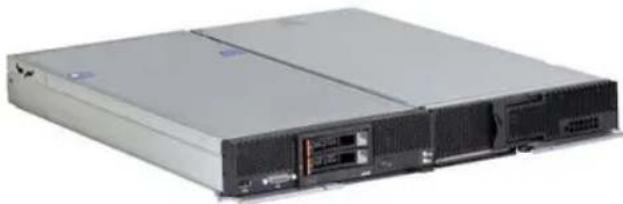
The following figure shows the IBM Flex System Storage Expansion Node attached to a compute node.
natural_image
Front view of a server rack unit with drive bays and ports (no visible text or labels)Figure 6. IBM Flex System Storage Expansion Node (right) attached to a compute node (left)
The ordering information for the Storage Expansion Node is shown in the following table.
Table 12. Ordering part number and feature code
| Part number | Feature code* | Description | Maximum supported |
| 68Y8588 | A3JF | IBM Flex System Storage Expansion Node | 1 |
* The feature is not available to be configured using model 7863-10X in e-config. Use model 8737-15X instead.
The Storage Expansion Node has the following features:
Internal tape drives
The server does not support an internal tape drive. However, it can be attached to external tape drives using Fibre Channel connectivity.
Optical drives
The server does not support an internal optical drive option. However, you can connect an external USB optical drive, such as the IBM and Lenovo part number 73P4515 or 73P4516, or use the remote media feature of the IMMv2 and the Chassis Management Module.
Note: The USB port on the compute nodes supply up to 0.5 A at 5 V. For devices that require more power, an additional power source will be required.
Embedded 10Gb Virtual Fabric Adapter
Some models of the x240 include an Embedded 10Gb Virtual Fabric Adapter (VFA, also known as LAN on Motherboard or LOM) built into the system board. Table 2 lists what models of the x240 include the Embedded 10Gb Virtual Fabric Adapter. Each x240 model that includes the embedded 10Gb VFA also has the Compute Node Fabric Connector installed in I/O connector 1 (and physically screwed onto the system board) to provide connectivity to the Enterprise Chassis midplane. Figure 3 shows the location of the Fabric Connector.
The Fabric Connector enables port 1 on the embedded 10Gb VFA to be routed to I/O module bay 1 and port 2 to be routed to I/O module bay 2. The Fabric Connector can be unscrewed and removed, if required, to allow the installation of an I/O adapter on I/O connector 1.
The Embedded 10Gb VFA is based on the Emulex BladeEngine 3 (BE3), which is a single-chip, dual-port 10 Gigabit Ethernet (10GbE) Ethernet Controller. These are some of the features of the Embedded 10Gb VFA:
• PCI-Express Gen2 x8 host bus interface
• Supports connection to 10 Gb and 1 Gb Flex System Ethernet switches
• Supports multiple virtual NIC (vNIC) functions
• TCP/IP Offload Engine (TOE enabled)
I/O expansion options
The x240 has two I/O expansion connectors for attaching I/O adapter cards. There is a third expansion connector designed to connect an expansion node such as the PCIe Expansion Node. The I/O expansion connectors are a very high-density 216-pin PCIe connector. Installing I/O adapter cards allows the server to connect with switch modules in the IBM Flex System Enterprise Chassis. Each slot has a PCI Express 3.0 x16 host interface and both slots support the same form-factor adapters.
The following figure shows the location of the I/O expansion connectors.

natural_image
Internal view of a server rack with multiple drive bays and memory units (no visible text or labels)Figure 7. Location of the I/O adapter slots in the IBM Flex System x240 Compute Node
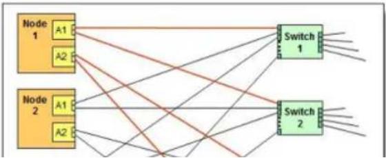
All I/O adapters are the same shape and can be used in any available slot.. A compatible switch or pass-through module must be installed in the corresponding I/O bays in the chassis, as indicated in the following table. Installing two switches means that all ports of the adapter are enabled, which improves performance and network availability.
Table 14. Adapter to I/O bay correspondence
The following figure shows the location of the switch bays in the IBM Flex System Enterprise Chassis.

Figure 8. Location of the switch bays in the IBM Flex System Enterprise Chassis
The following figure shows how two-port adapters are connected to switches installed in the chassis.
flowchart
graph TD
    subgraph Node 1
        A1 --> Switch1
        A2 --> Switch1
    end
    subgraph Node 2
        A1 --> Switch2
        A2 --> Switch2
    end
    A1 --> Switch1
    A2 --> Switch1
    A1 --> Switch2
    A2 --> Switch2
    Switch1 --> Output1
    Switch2 --> Output2
    style Node 1 fill:#FFD700,stroke:#333
    style Node 2 fill:#FFD700,stroke:#333
IBM Flex System PCIe Expansion Node
The x240 supports the attachment of the IBM Flex System PCIe Expansion Node. The IBM Flex System PCIe Expansion Node provides the ability to attach additional PCI Express cards such as High IOPS SSD adapters, fabric mezzanine cards, and next-generation graphics processing units (GPU) to supported IBM Flex System compute nodes. This capability is ideal for many applications that require high performance I/O, special telecommunications network interfaces, or hardware acceleration using a PCI Express card. The PCIe Expansion Node supports up to four PCIe 2.0 adapters and two additional Flex System expansion adapters.
The PCIe Expansion Node is attached to the x240 as shown in the following figure.

Figure 10. PCIe Expansion Node
The ordering information for the PCIe Expansion Node is shown in the following table.
Table 15. Ordering part number and feature code
| Part number | Feature code | Description | Maximum supported |
| 81Y8983 | A1BV* | IBM Flex System PCIe Expansion Node | 1 |
Note: The use of the PCIe Expansion Node requires that the x240 Compute Node have both processors installed.
For more information, see the IBM Redbooks Product Guide on the IBM Flex System PCIe Expansion Node, http://www.redbooks.ibm.com/abstracts/tips0906.html?Open
Network adapters
As described in "Embedded 10Gb Virtual Fabric Adapter," certain models (those with a model number of the form x2x) have a 10Gb Ethernet controller on the system board, and its ports are routed to the midplane and switches installed in the chassis via a Compute Note Fabric Connector that takes the place of an adapter in I/O slot 1.
Models without the Embedded 10Gb Virtual Fabric Adapter (those with a model number of the form x1x) do not include any other Ethernet connections to the Enterprise Chassis midplane as standard. Therefore, for those models, an I/O adapter must be installed in either I/O connector 1 or I/O connector 2 to provide network connectivity between the server and the chassis midplane and ultimately to the network switches.
The following table lists the supported network adapters and upgrades. Adapters can be installed in either slot. However, compatible switches must be installed in the corresponding bays of the chassis. All adapters can also be installed in the PCIe Expansion Node. The "Maximum supported" column indicates the number of adapter than can be installed in the server and in the PCIe Expansion Node (PEN).
Table 16. Network adapters
| Part number | Feature code | Description | Number of ports | Maximum supported (x240° / PEN) |
| 40 Gb Ethernet | ||||
| 90Y3482 | A3HK | IBM Flex System EN6132 2-port 40Gb Ethernet Adapter | 2 | 2 / None |
| 10 Gb Ethernet | ||||
| 88Y5920 | A4K3 | IBM Flex System CN4022 2-port 10Gb Converged Adapter | 2 | 2 / 2 |
| 90Y3554 | A1R1 | IBM Flex System CN4054 10 Gb Virtual Fabric Adapter | 4 | 2 / 2 |
| 90Y3558 | A1R0 | IBM Flex System CN4054 Virtual Fabric Adapter (SW | License | 2 / 2 |
Storage host bus adapters
The following table lists storage HBAs supported by the x240 server, both internally in the compute node and in the PCIe Expansion Node.
Table 17. Storage adapters
| Part number | Feature code | Description | Number of ports | Maximum supported (x240° / PEN) |
| Fibre Channel | ||||
| 88Y6370 | A1BP | IBM Flex System FC5022 2-port 16Gb FC Adapter | 2 | 2 / 2 |
| 95Y2386 | A45R | IBM Flex System FC5052 2-port 16Gb FC Adapter | 2 | 2 / 2 |
| 95Y2391 | A45S | IBM Flex System FC5054 4-port 16Gb FC Adapter | 4 | 2 / 2 |
| 69Y1942 | A1BQ | IBM Flex System FC5172 2-port 16Gb FC Adapter | 2 | 2 / 2 |
| 69Y1938 | A1BM | IBM Flex System FC3172 2-port 8Gb FC Adapter | 2 | 2 / 2 |
| 95Y2375 | A2N5 | IBM Flex System FC3052 2-port 8Gb FC Adapter | 2 | 2 / 2 |
* For x2x models with the Embedded 10Gb Virtual Fabric Adapter standard, the Compute Node Fabric Connector occupies the same space as an I/O adapter in I/O slot 1, so you have to remove the Fabric Connector if you plan to install an adapter in I/O slot 1.
For adapter-to-switch compatibility, see the IBM Flex System Interoperability Guide: http://www.redbooks.ibm.com/fsig
PCIe SSD adapters
The compute node supports the High IOPS SSD adapters listed in the following table.
Note: These adapters are installed in an attached PCIe Expansion Node.
Table 18. SSD adapters
| Part number | Feature | Description | Maximum |
http://www.redbooks.ibm.com/abstracts/tips0937.html
• IBM High IOPS SSD PCIe Adapters
http://www.redbooks.ibm.com/abstracts/tips0729.html
GPU and Crypto adapters
The compute node supports the GPU and Crypto adapters listed in the following table.
Note: These adapters are installed in an attached PCIe Expansion Node.
Table 19. GPU and Crypto adapters
| Part number | Feature code | Description | Maximum supported |
| 94Y5960 | A1R4 | NVIDIA Tesla M2090 (full-height adapter) | 1* |
| 47C2120 | A4F1 | NVIDIA GRID K1 for IBM Flex System PCIe Expansion Node | 1† |
| 47C2121 | A4F2 | NVIDIA GRID K2 for IBM Flex System PCIe Expansion Node | 1† |
| 47C2119 | A4F3 | NVIDIA Tesla K2.0 for IBM Flex System PCIe Expansion Node | 1† |
| 47C2122 | A4F4 | Intel Xeon Phi 5110P for IBM Flex System PCIe Expansion Node | 1† |
| None | 4809** | IBM 4765 Crypto Card (full-height adapter) | 2 |
* When this double-wide adapter is installed in the PCIe Expansion Node, it occupies both full-height slots. The low-profile slots and Flex System I/O expansion slots can still be used.
† If installed, only this adapter is supported in the system. No other PCIe adapters may be installed.
** Orderable as separate MTM 4765-001 feature 4809. Available via AAS (e-config) only.
Power supplies
Server power is derived from the power supplies installed in the chassis. There are no server options regarding power supplies.
Integrated virtualization
Installing two preloaded keys will prevent ESXi from booting as described in http://kb.vmware.com/kb/1035107. Having two keys installed provides a backup boot device, both devices are listed in the boot menu, which allows you to boot from either device or to set one as a backup in case the first one gets corrupted.
Note: The x240 USB Enablement Kit and USB memory keys are not supported if the SSD Expansion Kit (90Y4391) is already installed, because these kits occupy the same location in the server.
Table 20. Virtualization options
| Part number | Feature code | Description | Maximum supported |
| 49Y8119 | A3A3 | x240 USB Enablement Kit | 1 |
| 41Y8298 | A2G0 | IBM Blank USB Memory Key for VMware ESXi Downloads | 2 |
| 41Y8300 | A2VC | IBM USB Memory Key for VMware ESXi 5.0 | 1 |
| 41Y8307 | A383 | IBM USB Memory Key for VMware ESXi 5.0 Update 1 | 1 |
| 41Y8311 | A2R3 | IBM USB Memory Key for VMware ESXi 5.1 | 1 |
| 41Y8382 | A4WZ | IBM USB Memory Key for VMware ESXi 5.1 Update 1 | 1 |
| 41Y8385 | A584 | IBM USB Memory Key for VMware ESXi 5.5 | 1 |
Light path diagnostics
For quick problem determination when located physically at the server, the x240 offers a three-step guided path:
- The Fault LED on the front panel
- The light path diagnostics panel, shown in the following figure.
- LEDs next to key components on the system board
The x240 light path diagnostics panel is visible when you remove the server from the chassis. The panel is located on the top right-hand side of the compute node, as shown in the following figure.

natural_image
Close-up of a computer RAM module with visible pins and connectors (no readable text or symbols)Figure 11. Location of x240 light path diagnostics panel
To illuminate the light path diagnostics LEDs, power off the compute node, slide it out of the chassis, and press the power button. The power button doubles as the light path diagnostics remind button when the server is removed from the chassis.
The magnitudes of the LEDs in the light with disconnection panel are listed in the following table:
Remote management
The server contains an IBM Integrated Management Module II (IMM2), which interfaces with the advanced management module in the chassis. The combination of these provides advanced service-processor control, monitoring, and an alerting function. If an environmental condition exceeds a threshold or if a system component fails, LEDs on the system board are lit to help you diagnose the problem, the error is recorded in the event log, and you are alerted to the problem. A virtual presence capability comes standard for remote server management.
Remote server management is provided through industry-standard interfaces:
• Intelligent Platform Management Interface (IPMI) Version 2.0
• Simple Network Management Protocol (SNMP) Version 3
• Common Information Model (CIM)
- Web browser
The server also supports virtual media and remote control features, which provide the following functions:
- Remotely viewing video with graphics resolutions up to 1600x1200 at 75 Hz with up to 23 bits per pixel, regardless of the system state
• Remotely accessing the server using the keyboard and mouse from a remote client - Mapping the CD or DVD drive, diskette drive, and USB flash drive on a remote client, and mapping ISO and diskette image files as virtual drives that are available for use by the server
- Uploading a diskette image to the IMM2 memory and mapping it to the server as a virtual drive
• Capturing blue-screen errors
Supported operating systems
The server supports the following operating systems:
• Microsoft Windows Server 2008 HPC Edition
• Microsoft Windows Server 2008 R2
• Microsoft Windows Server 2008, Datacenter x64 Edition
• Microsoft Windows Server 2008, Enterprise x64 Edition
• Microsoft Windows Server 2008, Standard x64 Edition
• Microsoft Windows Server 2008, Web x64 Edition
• Microsoft Windows Server 2012
Physical specifications
Dimensions and weight (approximate):
• Height: 56 mm (2.2 in)
• Depth: 492 mm (19.4 in)
• Width: 217 mm (8.6 in)
• Maximum weight: 7.1 kg (15.6 lb)
Shipping dimensions and weight (approximate):
• Height: 197 mm (7.8 in)
• Depth: 603 mm (23.7 in)
• Width: 430 mm (16.9 in)
• Weight: 8 kg (17.6 lb)
Supported environment
The IBM Flex System x240 compute node complies with ASHRAE Class A3 specifications.
This is the supported operating environment:
Power on:
• Temperature: 5 - 40 °C (41 - 104 °F)
• Humidity, non-condensing: -12 °C dew point (10.4 °F) and 8 - 85% relative humidity
• Maximum dew point: 24 °C (75 °F)
• Maximum altitude: 3048 m (10,000 ft)
• Maximum rate of temperature change: 5 °C/hr (41 °F/hr)
Power off:
• Temperature: 5 - 45 °C (41 - 113 °F)
• Relative humidity: 8 - 85%
• Maximum dew point: 27 °C (80.6 °F)
Storage (non-operating):
Warranty options
The IBM Flex System x240 Compute Node has a three-year on-site warranty with 9x5 next-business-day terms. IBM offers the warranty service upgrades through IBM ServicePac, discussed in this section. The IBM ServicePac is a series of prepackaged warranty maintenance upgrades and post-warranty maintenance agreements with a well-defined scope of services, including service hours, response time, term of service, and service agreement terms and conditions.
IBM ServicePac offerings are country-specific. That is, each country might have its own service types, service levels, response times, and terms and conditions. Not all covered types of ServicePac might be available in a particular country. For more information about IBM ServicePac offerings available in your country, see the IBM ServicePac Product Selector at https://www-304.ibm.com/sales/gss/download/spst/servicepac.
The following table explains warranty service definitions in more detail.
Table 22. Warranty service definitions
| Term | Description |
| IBM on-site repair (IOR) | A service technician will come to the server's location for equipment repair. |
| 24x7x2 hour | A service technician is scheduled to arrive at your customer's location within two hours after remote problem determination is completed. We provide 24-hour service, every day, including IBM holidays. |
| 24x7x4 hour | A service technician is scheduled to arrive at your customer's location within four hours after remote problem determination is completed. We provide 24-hour service, every day, including IBM holidays. |
| 9x5x4 hour | A service technician is scheduled to arrive at your customer's location within four business hours after remote problem determination is completed. We provide service from 8:00 a.m. to 5:00 p.m. in the customer's local time zone, Monday through Friday, excluding IBM holidays. If after 1:00 p.m. it is determined that on-site service is required, the customer can expect the service technician to arrive the morning of the following business day. For noncritical service requests, a service technician will arrive by the end of the following business day. |
| 9x5 next business day | A service technician is scheduled to arrive at your customer's location on the business day after we receive your call, following remote problem determination. We provide service from 8:00 a.m. to 5:00 p.m. in the customer's local time zone, Monday through Friday, excluding IBM holidays. |
Regulatory compliance
The server conforms to the following standards:
• ASHRAE Class A3
• FCC - Verified to comply with Part 15 of the FCC Rules Class A
• Canada ICES-004, issue 3 Class A
• UL/IEC 60950-1
• CSA C22.2 No. 60950-1
NOM-019
• Argentina IEC 60950-1
• Japan VCCI, Class A
• IEC 60950-1 (CB Certificate and CB Test Report)
• China CCC (GB4943); (GB9254, Class A); (GB17625.1)
• Taiwan BSMI CNS13438, Class A; CNS14336
• Australia/New Zealand AS/NZS CISPR 22, Class A
• Korea KN22, Class A, KN24
• Russia/GOST ME01, IEC 60950-1, GOST R 51318.22, GOST R
• 51318.249, GOST R 51317.3.2, GOST R 51317.3.3
IEC 60950-1 (CB Certificate and CB Test Report)
• CE Mark (EN55022 Class A, EN60950-1, EN55024, EN61000-3-2,
EN61000-3-3)
• CISPR 22, Class A
• TUV-GS (EN60950-1/IEC 60950-1, EK1-ITB2000)
IBM Global Financing
IBM Global Financing can help you obtain the IT solution you need while preserving funding for other strategic investments and optimizing cash flow. Our Fair Market Value (FMV) lease helps ensure that you have the latest IBM technology and with our mid-lease upgrade capability, you can increase the capacity of the system with little to no change in monthly payments. At the end of the lease, take advantage of our flexible end-of-lease options to fit your changing business needs. IBM Global Financing has the breadth and depth of offerings, longevity, proven success and global reach to help you develop a robust financing and asset management strategy that provides you the opportunity to leverage new technologies and turn your ambitious vision into a tangible solution.
Here are some other reasons why working with us makes solid financial sense:
- Expand your purchasing power—Affordable monthly payments allow you to change the technology acquisition discussion from "what can I afford right now" to "what solution is really right for my business." IBM Global Financing allows you to expand your purchase power to get you the right solution.
- Accelerate your project's cash flow break-even point—Acquire your IBM technology today and begin to realize its benefits now. An FMV lease can help you get the solution you need now, with low monthly payments that better align upfront costs with the anticipated return on investment from the technology.
- Easy to acquire with affordable rates—We offer one-stop shopping for a total IT solution, so you can acquire IBM hardware, software, services and the financing you need—from one IT provider.
Plus, we provide simple, easy-to-understand contracts and quick approvals. As the world's largest IT financing provider, with an asset base of US\$35.8 billion and over 125,000 customers, IBM Global Financing offers highly competitive rates that promote low total cost of ownership and low monthly payments.
IBM Global Financing operates in more than 50 countries. Go to http://ibm.com/financing for financing options in your country and to contact a local financing specialist.
IBM Global Financing offerings are provided through IBM Credit LLC in the United States and other IBM subsidiaries and divisions worldwide to qualified commercial and government clients. Rates and availability subject to client's credit rating, financing terms, offering type, equipment and product type and options, and may vary by country. Non-hardware items must be one-time, non-recurring charges and are financed by means of loans. Other restrictions may apply. Rates and offerings are subject to change, extension or withdrawal without notice and may not be available in all countries. Please contact your local
Related publications and links
For more information, see the following resources:
- IBM US Announcement Letter http://ibm.com/common/ssi/cgi-bin/ssalias?infotype=dd&subtype=ca&htmlfid=897/ENUS112-052
- IBM US Announcement Letter for x240 model 8737-15X in e-config http://ibm.com/common/ssi/cgi-bin/ssialis?infotype=dd&subtype=ca&htmlfid=897/ENUS113-110
- IBM Flex System x240 Compute Node product page http://ibm.com/systems/flex/compute-nodes/x86/bto/
- IBM Flex System Information Center http://publib.boulder.ibm.com/infocenter/flexsys/information/index.jsp
- IBM Flex System x240 Compute Node Installation and Service Guide http://publib.boulder.ibm.com/infocenter/flexsys/information/topic/com.ibm.acc.8737.doc/printable_doc.html
- ServerProven for IBM Flex System http://ibm.com/systems/info/x86servers/serverproven/compat/us/flexsystems.html
- ServerProven hardware compatibility page for the x240 http://ibm.com/systems/info/x86servers/serverproven/compat/us/flex/8737_7863.html
- ServerProven compatibility page for operating system support http://ibm.com/systems/info/x86-servers/serverproven/compat/us/nos/flexmatrix.shtml
- IBM Redbooks® Product Guides for IBM Flex System servers and options http://www.redbooks.ibm.com/Redbooks.nsf/portals/puresystems?Open&page=pgbycat
- IBM Flex System Interoperability Guide http://www.redbooks.ibm.com/fsig
- Configuration and Option Guide
http://www.ibm.com/systems/xbc/cog/
• xREF - IBM System x Reference Sheets http://www.redbooks.ibm.com/xref
• IBM System x Support Portal http://ibm.com/support/entry/portal/ - IBM System Storage® Interoperation Center http://www.ibm.com/systems/support/storage/ssic
Notices
This information was developed for products and services offered in the U.S.A.
IBM may not offer the products, services, or features discussed in this document in other countries. Consult your local IBM representative for information on the products and services currently available in your area. Any reference to an IBM product, program, or service is not intended to state or imply that only that IBM product, program, or service may be used. Any functionally equivalent product, program, or service that does not infringe any IBM intellectual property right may be used instead. However, it is the user's responsibility to evaluate and verify the operation of any non-IBM product, program, or service. IBM may have patents or pending patent applications covering subject matter described in this document. The furnishing of this document does not give you any license to these patents. You can send license inquiries, in writing, to:
IBM Director of Licensing, IBM Corporation, North Castle Drive, Armonk, NY 10504-1785 U.S.A.
The following paragraph does not apply to the United Kingdom or any other country where such provisions are inconsistent with local law: INTERNATIONAL BUSINESS MACHINES CORPORATION PROVIDES THIS PUBLICATION "AS IS" WITHOUT WARRANTY OF ANY KIND, EITHER EXPRESS OR IMPLIED, INCLUDING, BUT NOT LIMITED TO, THE IMPLIED WARRANTIES OF NON-INFRINGEMENT, MERCHANTABILITY OR FITNESS FOR A PARTICULAR PURPOSE. Some states do not allow disclaimer of express or implied warranties in certain transactions, therefore, this statement may not apply to you. This information could include technical inaccuracies or typographical errors. Changes are periodically made to the information herein; these changes will be incorporated in new editions of the publication. IBM may make improvements and/or changes in the product(s) and/or the program(s) described in this publication at any time without notice.
Any references in this information to non-IBM Web sites are provided for convenience only and do not in any manner serve as an endorsement of those Web sites. The materials at those Web sites are not part of the materials for this IBM product and use of those Web sites is at your own risk. IBM may use or distribute any of the information you supply in any way it believes appropriate without incurring any obligation to you. Information concerning non-IBM products was obtained from the suppliers of those products, their published announcements or other publicly available sources. IBM has not tested those products and cannot confirm the accuracy of performance, compatibility or any other claims related to non-IBM products. Questions on the capabilities of non-IBM products should be addressed to the suppliers of those products. This information contains examples of data and reports used in daily business operations. To illustrate them as completely as possible, the examples include the names of individuals, companies, brands, and products. All of these names are fictitious and any similarity to the names and addresses used by an actual business enterprise is entirely coincidental.
Any performance data contained herein was determined in a controlled environment. Therefore, the results obtained in other operating environments may vary significantly. Some measurements may have been made on development-level systems and there is no guarantee that these measurements will be the same on generally available systems. Furthermore, some measurement may have been estimated through extrapolation. Actual results may vary. Users of this document should verify the applicable data for their specific environment.
This document was created or updated on March 17, 2014.
Send us your comments in one of the following ways:
• Use the online Contact us review form found at: lbm.com/redbooks
- Send your comments in an e-mail to: redbook@us.ibm.com
- Mail your comments to: IBM Corporation, International Technical Support Organization Dept. HYTD Mail Station P099 2455 South Road Poughkeepsie, NY 12601-5400 U.S.A.
This document is available online at http://www.ibm.com/redbooks/abstracts/tips0860.html.
Trademarks
IBM, the IBM logo, and ibm.com are trademarks or registered trademarks of International Business Machines Corporation in the United States, other countries, or both. These and other IBM trademarked terms are marked on their first occurrence in this information with the appropriate symbol (® or *). Indicating US registered or common law trademarks owned by IBM at the time this information was published. Such trademarks may also be registered or common law trademarks in other countries. A current list of IBM trademarks is available on the Web at http://www.ibm.com/legal/copytrade.shtml
The following terms are trademarks of the International Business Machines Corporation in the United States, other countries, or both:
BladeCenter®
Calibrated Vectored Cooling™
IBM Flex System™
IBM®
PowerPO®
Redbooks®
Redbooks (logo)®
ServerProven®
ServicePad®
System Storage®
System x®


- IBM®
- Redbooks
- IBM Flex System x240 Compute Node (E5-2600)
- Key features
- Scalability and performance
- Availability and serviceability
- Manageability and security
- Energy efficiency
- Locations of key components and connectors
- Standard specifications
- Standard models
- Chassis support
- Processor options
- Memory options
- Internal storage
- ServeRAID M5115 SAS/SATA controller
- Internal drive options
- IBM Flex System Storage Expansion Node
- Internal tape drives
- Optical drives
- Embedded 10Gb Virtual Fabric Adapter
- I/O expansion options
- IBM Flex System PCIe Expansion Node
- Network adapters
- Storage host bus adapters
- PCIe SSD adapters
- GPU and Crypto adapters
- Power supplies
- Integrated virtualization
- Light path diagnostics
- Remote management
- Supported operating systems
- Physical specifications
- Supported environment
- Warranty options
- Regulatory compliance
- IBM Global Financing
- Related publications and links
- Notices
- Trademarks
Mærke : IBM
Model : Flex System x240
Kategori : Server