LDW45S10 - Opvaskemaskine Logik - Gratis brugsanvisning og manual
Find enhedens vejledning gratis LDW45S10 Logik i PDF-format.


Brugerspørgsmål om LDW45S10 Logik
0 spørgsmål om dette apparat. Besvar dem du kender, eller stil dit eget.
Stil et nyt spørgsmål om dette apparat
Download vejledningen til din Opvaskemaskine i PDF-format gratis! Find din vejledning LDW45S10 - Logik og tag din elektroniske enhed tilbage i hånden. På denne side er alle dokumenter nødvendige for brugen af din enhed offentliggjort. LDW45S10 af mærket Logik.
BRUGSANVISNING LDW45S10 Logik


LOGIK
Installationsvejledning til opvaskemaskine
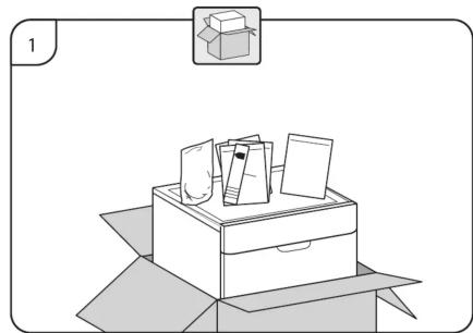
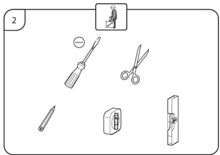
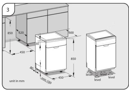
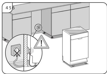
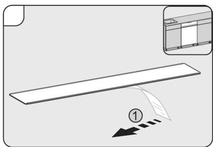
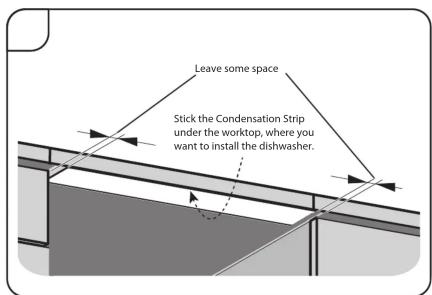
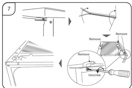
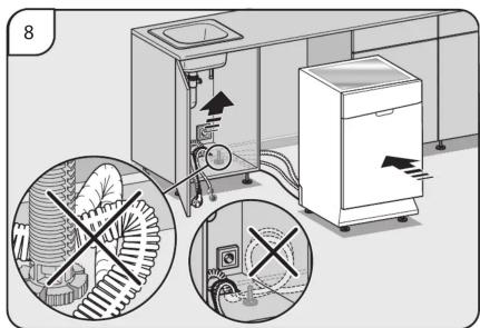
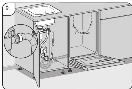
Tak fordi du har købt en Logik opvaskemaskine. Se denne vejledning for installationsprocessen. 1. Fjern al emballage, før du placerer maskinen. (Fig. 1) 2. Sørg for, at opvaskemaskinen installeres af en kvalificeret tekniker. Se de nødvendige værktøjer i Fig. 2. 3. Sørg for, at der er plads på hver side af enheden for at tillade let sideværts bevægelse til service, når det er nødvendigt. God nivellering er afgørende for korrekt lukning og tætning af døren. Når enheden er korrekt nivelleret, må døren ikke ramme den indvendige beklædning på nogen af siderne af kabinettet. De justerbare fødder kan løsnes eller strammes for at opnå den optimale nivellering af enheden. (Fig. 3) 4. Hvis det er nødvendigt, kan opvaskemaskinens bordplade fjernes. Højden uden bordpladen er 820 mm. Figur 3 viser de minimale dimensioner, der kræves for at placere opvaskemaskinen i et indbygget køkkenmøbel. Tilslut ikke enheden til strømforsyningen før installation. Sørg for, at du ikke installerer enheden lige foran strømforsyningen. Dette er for at undgå potentiel skade på bagsiden af enheden. (Fig. 4) 5. Kondensstrimmelen skal monteres på undersiden af bordpladen over din opvaskemaskine for at beskytte den mod fugt. Dens formål er at beskytte bordpladens underside mod damp, der stiger op fra opvaskemaskinen. (Fig. 5 og 6) - Sørg for, at overfladen er ren, før du sætter kondensstrimmelen på undersiden af bordpladen. - Fjern bagpapiret fra kondensstrimmelen. (Fig. 5) - Sæt kondensstrimmelen på undersiden af bordpladen. (Fig. 6) BEMÆRK: MANGLENDE MONTERING AF KONDENSSTRIMMELEN KAN MEDFØRE SKADE PÅ UNDERSIDEN AF DIN BORDPLADE! 6. Bordpladen kan fjernes ved at fjerne fastgørelsesskruerne bag på opvaskemaskinen (Fig. 7). Efter at have fjernet skruerne, løft og skub bordpladen fremad for at frigøre tapperne fra frontsektionen af opvaskemaskinen. Polystyrenblokken og tapperne bør gemmes til fremtidig brug. 7. Placer opvaskemaskinen ved siden af en vandhane og et afløb. Sørg for, at vandindløbs- og afløbsslangen ikke er knækket eller klemt. Enheden må ikke stå på netledningen. (Fig. 8) 8. Sørg for, at dit VVS-arbejde er egnet til brug med opvaskemaskinen. Hvis du er i tvivl, så kontakt en kvalificeret VVS-installatør. Denne enhed SKAL tilsluttes KOLDVANDSFORSYNINGEN ved hjælp af den nye vandindløbsslange. GAMLE SLANGESÆT MÅ IKKE GENBRUGES. Vandtrykket fra vandforsyningen skal være mindst 0,04 MPa og maksimalt 1,00 MPa.
- (fortsat)
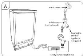
- Tilslut den ene ende af sikkerhedsvandforsyningsslangen til din opvaskemaskine, og tilslut derefter den anden ende af slangen til din vandforsyning (Fig. A). Sørg for, at den sorte gummipakning er på plads. • Efter tilslutning af slangen skal du åbne for vandforsyningen og kontrollere for utætheder.
- Tilslut opvaskemaskinen til stikkontakten.
BEMÆRK: DU KAN BRUGE EN Y-ADAPTER (IKKE INKLUDERET) TIL YDERLIGERE VANDFORSYNING TIL ET ANDET APPARAT, FOR EKSEMPEL EN VASKEMASKINE. DETTE GÆLDER KUN FOR KOLDT VAND. EN Y-ADAPTER KAN KØBES I DE FLESTE GØR-DET-SELV-BUTIKKER. (FIG. A)
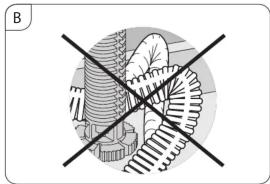
- Bøj ikke afløbsslangen. (FIG. B)
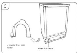
- Du kan bruge U-formet afløbsslangeholder til at fastgøre afløbsslangen og undgå, at den bøjes. (FIG. C)
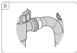
- Fastgør afløbsslangen til spildevandsrøret for at undgå, at den falder af under vaskeprocessen. (FIG. 9 OG D)
BEMÆRK: SPILDEVANDSRØRET MÅ KUN TILSLUTTES TIL AFLØBSSYSTEMET FOR SPILDEVAND OG IKKE TIL OVERFLADEVANDSAFLØBSSYSTEMET.
AFLØBSSLANGEN SKAL PLACERES MELLEM 40 CM OG 100 CM FRA GULVNIVEAU OG MÅ IKKE FORLÆNGES, ELLERS KAN ENHEDEN MULIGVIS IKKE UDLEDE SPILDEVANDET KORREKT.




Mærke : Logik
Model : LDW45S10
Kategori : Opvaskemaskine