
Colt (1992) - Bil MITSUBISHI - Gratis brugsanvisning og manual
Find enhedens vejledning gratis Colt (1992) MITSUBISHI i PDF-format.


Brugerspørgsmål om Colt (1992) MITSUBISHI
0 spørgsmål om dette apparat. Besvar dem du kender, eller stil dit eget.
Stil et nyt spørgsmål om dette apparat
Download vejledningen til din Bil i PDF-format gratis! Find din vejledning Colt (1992) - MITSUBISHI og tag din elektroniske enhed tilbage i hånden. På denne side er alle dokumenter nødvendige for brugen af din enhed offentliggjort. Colt (1992) af mærket MITSUBISHI.
BRUGSANVISNING Colt (1992) MITSUBISHI
ENGINE
CONTENTS
E11AA-
SPECIFICATIONS 2
General Specifications 2
Service Specifications 3
Sealants 4
SPECIAL TOOLS 5
ENGINE <4G1> 7
SERVICE ADJUSTMENT PROCEDURES .... 7
Alternator Drive Belt Tension Inspection and Adjustment 7
Power Steering Oil Pump Drive Belt Tension Inspection and Adjustment ..... 7
Air Conditioner Compressor Drive Belt Tension Inspection and Adjustment ..... 8
Valve Clearance Inspection and Adjustment 9
Ignition Timing Inspection and Adjustment . 10
Idle Speed Inspection 12
Idle Mixture Inspection 12
Compression Pressure Inspection ..... 13
Manifold Vacuum Inspection 15
Timing Belt Tension Adjustment ..... 15
Basic Idle Speed Adjustment .... Refer to GROUP 13
CRANKSHAFT PULLEY 17
CAMSHAFT AND CAMSHAFT OIL SEAL .... 18
OIL PAN 20
CRANKSHAFT OIL SEAL 22
CYLINDER HEAD GASKET 24
TIMING BELT 28
ENGINE ASSEMBLY 30
ENGINE <4G9> 33
SERVICE ADJUSTMENT PROCEDURES .... 33
Alternator Drive Belt Tension Inspection and Adjustment 33
Power Steering Oil Pump Drive Belt Tension Inspection and Adjustment
Power Steering Oil Pump and Air Conditioner Compressor Drive Belt Tension Inspection and Adjustment
Valve Clearance Inspection and Adjustment 35
Ignition Timing Inspection and Adjustment . 35 Idle Speed Inspection .... 38
Idle Mixture Inspection 38
Compression Pressure Inspection .... 38-1 Manifold Vacuum Inspection .... 38-1
Timing Belt Tension Adjustment 39
Lash Adjusters Check <4G93> 40
Basic Idle Speed Adjustment .... Refer to GROUP 13
CRANKSHAFT PULLEY 42
CAMSHAFT AND CAMSHAFT OIL SEAL <4G92> 43
CAMSHAFT AND CAMSHAFT OIL SEAL <4G93> 45
OIL PAN 48
CRANKSHAFT OIL SEAL 50
CYLINDER HEAD GASKET <4G92> 54
CYLINDER HEAD GASKET <4G93> ..... 59
TIMING BELT <4G92> 64
TIMING BELT <4G93> 69
ENGINE ASSEMBLY <4G92> 73
ENGINE ASSEMBLY <4G93> 77
ENGINE <4D68> 79
SERVICE ADJUSTMENT PROCEDURES .... 79
Drive Belt Tension Inspection and Adjustment 79
Valve Clearance Inspection and Adjustment 81
Injection Timing Adjustment 82
Engine Idle Speed Inspection and Adjustment 85
Compression Pressure Inspection 86
Timing Belt Adjustment 87
CAMSHAFT AND CAMSHAFT OIL SEAL .... 90
OIL PAN 92
CRANKSHAFT FRONT OIL SEAL 94
CRANKSHAFT REAR OIL SEAL 95
CYLINDER HEAD GASKET 97
TIMING BELT AND TIMING BELT B ..... 103
ENGINE ASSEMBLY 108
NOTES
SPECIFICATIONS
GENERAL SPECIFICATIONS
E11CA--
| Items | 4G13 | 4G92 | 4G93 | 4D68 | |
| Number and arrangement of cylinder | 4, in-line | 4, in-line | 4, in-line | 4, in-line | |
| Total displacement | ml (cu.in.) | 1,299 (79.3) | 1,597 (97.5) | 1,834 (111.9) | 1,998 (121.9) |
| Bore × Stroke | mm (in.) | 71.0 × 82.0(2.80 × 3.23) | 81.0 × 77.5(3.19 × 3.05) | 81.0 × 89.0(3.19 × 3.50) | 82.7 × 93.0(3.26 × 3.66) |
| Compression ratio | 9.5 | 10.0 | 10.5 | 22.4 | |
| Firing order | 1-3-4-2 | 1-3-4-2 | 1-3-4-2 | — | |
| Injection order | — | — | — | 1-3-4-2 | |
| Combustion chamber | Pentroof type | Pentroof type | Pentroof type | Swirl type | |
| Camshaft arrangement | Single overhead camshaft | Single overhead camshaft | Double overhead camshaft | Single overhead camshaft | |
| Valve timing | |||||
| Intake | Open | BTDC 15° | BTDC 14°BTDC 16°* | BTDC 20° | BTDC 20° |
| Close | ABDC 53° | ABDC 58°ABDC 42°* | ABDC 60° | ABDC 48° | |
| Exhaust | Open | BBDC 57° | BBDC 52°BBDC 54°* | BBDC 60° | BBDC 54° |
| Closed | ATDC 15° | ATDC 16°ATDC 6°* | ATDC 16° | ATDC 22° | |
| Rocker arm | Roller followertype | Roller followertype | Roller followertype | Roller followertype | |
| Lash adjuster | Not equipped | Not equipped | Equipped | Not equipped | |
NOTE
*: indicates specifications for MVV engines.
SERVICE SPECIFICATIONS
E11CB-
| Items | 4G13 | 4G92 | 4G93 | 4D68 |
| Standard value | ||||
| Drive belt deflection mm (in.) | ||||
| Alternator V-ribbed type | ||||
| When checked | 7.0-9.0(0.28-0.35) | 8.5-12.0(0.33-0.47) | 8.5-12.0(0.33-0.47) | 7.0-10.0(0.28-0.39) |
| When a new belt is installed | 5.5-7.0(0.21-0.28) | 7.0-8.5(0.28-0.33) | 7.0-8.5(0.28-0.33) | 6.0-7.0(0.24-0.28) |
| When a used belt is installed | 8.0 (0.31) | 9.5 (0.37) | 9.5 (0.37) | 8.0-9.0(0.31-0.35) |
| Power steering oil pump | ||||
| When checked | 5.5-7.5(0.22-0.30) | 9.5-11.5(0.374-0.453)*1 | 9.5-11.5(0.374-0.453)*1 | 5.5-8.0(0.22-0.39) |
| When a new belt is installed | 4.0-5.5(0.16-0.22) | 7.5-9.0(0.295-0.354)*1 | 7.5-9.0(0.295-0.354)*1 | 4.5-5.5(0.18-0.22) |
| When a used belt is installed | 5.5-7.5(0.22-0.30) | 9.5-11.5(0.374-0.453)*1 | 9.5-11.5(0.374-0.453)*1 | 6.0-7.0(0.24-0.28) |
| Air conditioner compressor | ||||
| When checked | 6.0-7.0(0.24-0.28) | — | — | 7.0-8.0(0.28-0.31) |
| When a new belt is installed | 5.0-6.0(0.20-0.24) | — | — | 5.0-6.0(0.20-0.24) |
| When a used belt is installed | 6.0-7.0(0.24-0.28) | — | — | 7.0-8.0(0.28-0.31) |
| Power steering oil pump and air conditioner compressor | ||||
| When checked | — | 6.8-7.6(0.268-0.299) | 6.8-7.6(0.268-0.299) | — |
| When a new belt is installed | — | 5.5-6.0(0.217-0.236) | 5.5-6.0(0.217-0.236) | — |
| When a used belt is installed | — | 6.8-7.6(0.268-0.299) | 6.8-7.6(0.268-0.299) | — |
| Basic ignition timing | 5°BTDC ± 2° | 5°BTDC ± 2° | 5°BTDC ± 2° | — |
| Injection timing | — | — | — | 9°ATDC |
| Idle speed r/min. | 750 ± 100 | 800 ± 100700 ± 100*2 | 800 ± 100 | 750 ± 100 |
| CO concentration and HC concentration at idle | ||||
| CO concentration % | 0.5 or less | 0.5 or less | 0.5 or less | — |
| HC concentration ppm | 100 or less | 100 or less | 100 or less | — |
| Compression pressure kPa (kg/cm2, psi) (250-400 r/min.) | 1400 (14.0, 199) | 1450 (14.5, 206) | 1500 (15.0, 213) | 3500 (35.0, 49.8) |
| Intake manifold vacuum kPa (kg/cm2, in.Hg) | Approx. 71(530, 21) | Approx. 67(500, 20) | Approx. 67(500, 20) | — |
| Valve clearance (at hot) mm (in.) | ||||
| Intake | 0.20 (0.008) | 0.20 (0.008) | — | 0.25 (0.010) |
| Exhaust | 0.25 (0.010) | 0.30 (0.012) | — | 0.25 (0.010) |
| Timing belt tension mm (in.) | — | 33 (1.30) | — | 4-5 (0.16-0.20) |
| LimitCompression pressurekPa (kg/cm ^2 , psi) (250–400 r/min.) | min. 1000(10.0, 142) | min. 1100(11.0, 156) | min. 1150(11.5, 164) | min. 2560(25.6, 364) |
| Compression pressuredifference of all cylinderkPa (kg/cm ^2 , psi) | max. 100 (1.0, 14) | max. 100 (1.0, 14) | max. 100 (1.0, 14) | max. 300 (3.0, 43) |
NOTE
^1 : indicates specifications for vehicles without air conditioner.
^2 : indicates specifications for MW engines.
SEALANTS
E11CE--
| Engine | Items | Specified sealant | Remarks |
| 4G1 | Oil pan and cylinder block | MITSUBISHI GENUINE PART MD997110 or equivalent | Semi-drying sealant |
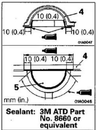
| 4G9 | Semi-circular packing and rocker cover seal, and cylinder head sealOil pan and cylinder blockFlywheel assemblyor drive platemounting bolt threadsThermostat case assembly and cylinder block seal | 3M ATD Part No. 8660 or equiv-alentMITSUBISHI GENUINE PART MD970389 or equivalent3M Stud locking 4170 or equiva-lentMITSUBISHI GENUINE PART MD970389 or equivalent | Semi-drying sealantSemi-drying sealant |
| 4D6 | Semi-circular packing and rocker cover seal, and cylinder head sealOil pan and cylinder blockThermostat case assembly and cylinder block seal | 3M ATD Part No. 8660 or equiv-alentMITSUBISHI GENUINE PART MD970389 or equivalentMITSUBISHI GENUINE PART MD970389 or equivalent | Semi-drying sealantSemi-drying sealant |
SPECIAL TOOLS
E11DA--
| Tool | Number | Name | Use | Application | ||
| 4G1 | 4G9 | 4D6 | ||||
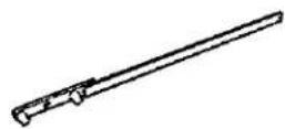 | MD998747 | Crankshaft pulley holder | Supporting crankshaft pulley | ○ | ||
 | MB990767 | End yoke holder | Supporting camshaft pulley Supporting crankshaft pulley | ○ | ○○ | ○ |
| (HWST) | MD998719 or MD998754 | Crankshaft pulley holder pin | ||||
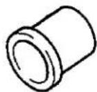 | MD998306 | Camshaft oil seal installer | Installation of camshaft oil seal | ○ | ||
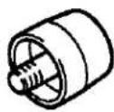 | MD998307 | Camshaft oil seal installer | ||||
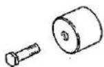 | MD998713 | Camshaft oil seal installer | Installation of camshaft oil seal | ○ | ||
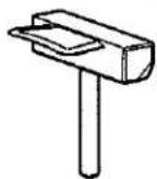 | MD998727 | Oil pan remover | Removal of oil pan | ○ | ○ | ○ |
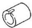 | MD998716 | Crankshaft wrench | Rotation of crankshaft when installing timing belt | ○ | ||
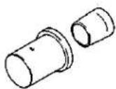 | MD998717 | Crankshaft front oil seal installer | Installation of crankshaft front oil seal | ○ | ○ | |
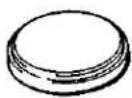 | MD998011 | Crankshaft rear oil seal installer | Installation of crankshaft rear oil seal | ○ | ||
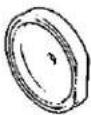 | MD998776 | Crankshaft rear oil seal installer | Installation of crankshaft rear oil seal | ○ | ○ | |
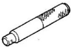 | MB990938 | Handle | ||||
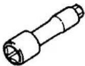 | MD998360 | Cylinder head bolt wrench | Removal and installation of cylinder head assembly | ○ | ||
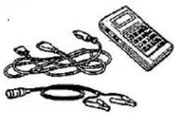 | MB991341 | Multi-use tester sub assembly | ○ | ○ | ||
 | ROM pack (for multi-use tester) (For the number, refer to GROUP 00-) (Precautions Before Service) | |||||
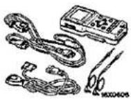 | MB991502 | MUT-II sub assembly | ○ | ○ | ||
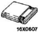 | ROM pack | |||||
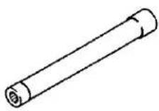 | GENERAL SERVICE TOOL | Cylinder head bolt wrench | Loosening and tightening of cylinder head bolt | ○ | ||
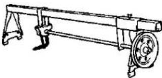 | GENERAL SERVICE TOOL MZ203827 | Mechanic hang-er, engine | Supporting engine assembly when removing and instal-ling transmission | ○ | ○ | ○ |
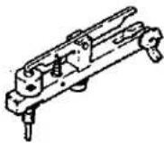 | MD998389 | Pre-stroke measuring adapter | Adjusting injection timing | ○ | ||
 | MD998364 | Camshaft oil seal installer | Installation of camshaft oil seal | ○ | ||
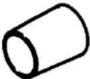 | MD998383 | Crankshaft front oil seal guide | Installation of crankshaft front oil seal | ○ | ||
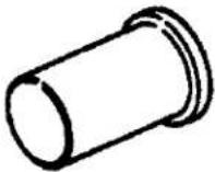 | MD998382 | Crankshaft front oil seal installer | ||||
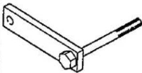 | MD998781 | Flywheel stopper | Securing the flywheelor drive plate | ○ | ○ | ○ |
ENGINE<4G1>
SERVICE ADJUSTMENT PROCEDURES
ALTERNATOR DRIVE BELT TENSION INSPECTION AND ADJUSTMENT E11FQBM
ALTERNATOR DRIVE BELT TENSION INSPECTION
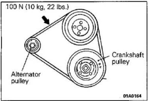
Check the tension by pulling or pushing at the centre of the belt between pulleys with a force of 100 N (10 kg, 22 lbs.) as shown in the figure.
Measure drive belt deflection amount.
Standard value: 7.0–9.0 mm (0.28–0.35 in.)
ALTERNATOR DRIVE BELT TENSION ADJUSTMENT
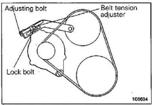
(1) Loosen the nut of the alternator pivot bolt.
(2) Loosen the lock bolt.
(3) Turn the adjusting bolt to adjust the amount of belt deflection to the standard value.
Standard value:
If used belt (with correct tension) is used;
8.0 mm (0.31 in.)
If a new belt is used; 5.5–7.0 mm (0.22–0.28 in.)
(4) Tighten the lock bolt.
Tightening torque:
12-15 Nm (1.2-1.5 kgm, 9-11 ft.lbs.)
(5) Tighten the nut of the alternator pivot bolt.
Tightening torque:
20-25 Nm (2.0-2.5 kgm, 14-18 ft.lbs.)
POWER STEERING OIL PUMP DRIVE BELT TEN- SION INSPECTION AND ADJUSTMENT
POWER STEERING OIL PUMP DRIVE BELT TENSION INSPECTION
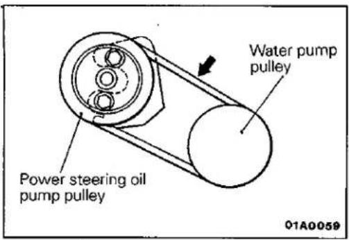
Check the tension by pulling or pushing at the centre of the belt between pulleys with a force of 100 N (10 kg, 22 lbs.).
Measure drive belt deflection amount.
Standard value: 5.5–7.5 mm (0.22–0.30 in.)
POWER STEERING OIL PUMP DRIVE BELT TENSION ADJUSTMENT
(1) Loosen power steering oil pump fixing bolt.
(2) Move power steering oil pump, tension belt moderately and adjust tension.
Standard value:
If used belt (with correct tension) is used; 5.5–7.5 mm (0.22–0.30 in.) If a new belt is used; 4.0–5.5 mm (0.16–0.22 in.)
(3) Tighten fixing bolt.
Tightening torque: 40 Nm (4.0 kgm, 29 ft.lbs.)
(4) Check belt tension and adjust if necessary.
[Unreadable]
AIR CONDITIONER COMPRESSOR DRIVE BELT TENSION INSPECTION AND ADJUSTMENT AIR CONDITIONER COMPRESSOR DRIVE BELT TENSION INSPECTION
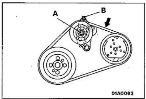
Check the tension by pulling or pushing at the centre of the belt between pulleys with a force of 100 N (10 kg, 22 lbs.). Measure drive belt deflection amount.
Standard value: 6.0–7.0 mm (0.24–0.28 in.)
AIR CONDITIONER COMPRESSOR DRIVE BELT TENSION ADJUSTMENT
(1) Loosen tension pulley fixing nut A.
(2) Adjust belt tension with adjusting bolt B.
If used belt (with correct tension) is used; 6.0–7.0 mm (0.24–0.28 in.)
If a new belt is used; 5.0–6.0 mm (0.20–0.24 in.)
(3) Tighten fixing nut A.
(4) Check the belt tension after driving.
Standard value: 6.0–7.0 mm (0.24–0.28 in.)
Standard value:
VALVE CLEARANCE INSPECTION AND ADJUSTMENT E11FDAW
(1) Start the engine and allow it to warm up until the engine coolant temperature reaches 80 to 95°C (176 to 203°F).
(2) Remove all spark plugs from the cylinder head for easy inspection.
(3) Remove the rocker cover.
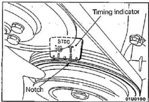
(4) Turn the crankshaft clockwise until the notch on the pulley is lined up with the "T" mark on the timing indicator.
natural_image
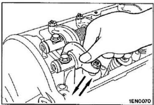
Illustration of a hand adjusting a mechanical component with arrows indicating motion (no text or symbols)(5) Move the rocker arms on the No. 1 and No. 4 cylinders up and down by hand to determine which cylinder has its piston at the top dead centre on the compression stroke. If both intake and exhaust valve rocker arms have a valve lash, the piston in the cylinder corresponding to these rocker arms is at the top dead centre on the compression stroke.
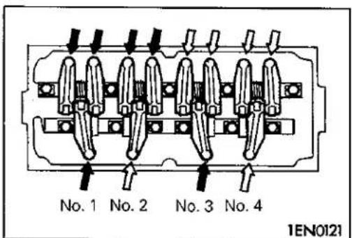
(6) Valve clearance inspection and adjustment can be performed on rocker arms indicated by white arrow ↓ when the No. 1 cylinder piston is at the top dead centre on the compression stroke, and on rocker arms indicated by solid arrows ↓ when the No. 4 cylinder piston is at the top dead centre on the compression stroke.
natural_image
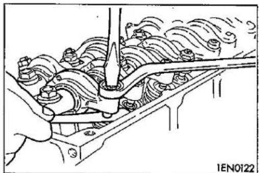
Technical illustration of a mechanical assembly with wavy components and a tool (no text or symbols)(7) Measure the valve clearance. If the valve clearance is not as specified, loosen the rocker arm lock nut and adjust the clearance using a feeler gauge while turning the adjusting screw.
Standard value (hot engine): Intake valve 0.20 mm (0.008 in.) Exhaust valve 0.25 mm (0.010 in.)
(8) While holding the adjusting screw with a screwdriver to prevent it from turning, tighten the lock nut securely.
(9) Turn the crankshaft through 360° to line up the notch on the crankshaft pulley with the "T" mark on the timing indicator.
(10) Repeat steps (7) and (8) on other valves for clearance adjustment.
(11) Install the rocker cover.
(12) Install the spark plugs and tighten to the specified torque.
Tightening torque: 25 Nm (2.5 kgm, 18 ft.lbs.)
natural_image
Technical line drawing of a vehicle suspension system with sensors and a digital meter (no text or symbols)IGNITION TIMING INSPECTION AND ADJUSTMENT E11FUBG
(1) Before inspection and adjustment set vehicle in the following condition.
- Engine coolant temperature: 80–95°C (176–203°F)
● Lamps, electric cooling fan and all accessories: OFF
• Transmission: Neutral
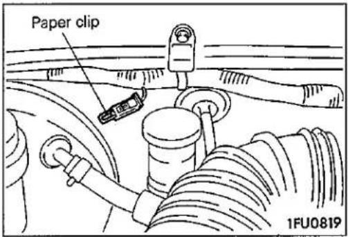
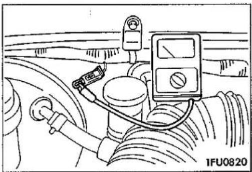
(2) Insert a paper clip into the 1 pin connector (blue) as shown in the illustration at left.
(3) Connect a primary-voltage-detection type of tachometer to the paper clip.
NOTE
Do not use the multi-use tester (MUT) or MUT-II.
If tested with the MUT or MUT-II connected to the diagnosis connector, the ignition timing will not be the basic timing but be ordinary timing.
(4) Set up a timing light.
(5) Start the engine and run at idle.
(6) Check that engine idle speed is within the standard value.
Standard value: 750 ± 100 r/min.
(7) Turn the ignition switch to OFF.
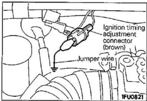
(8) Remove the waterproof connector from the ignition timing adjustment connector (brown).
(9) Connect the jumper wire with the clip to the ignition timing adjustment terminal, and earth this to the body as illustrated.
NOTE
Grounding this terminal sets the engine to the basic ignition timing.
(10) Start the engine and run it at idle.
(11) Check that basic ignition timing is within the standard value.
Standard value: 5° BTDC ±2°
natural_image
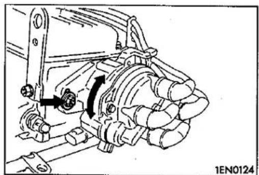
Mechanical assembly diagram showing a valve mechanism with rotating components (no text or labels)(12) If not within the standard value, loosen distributor fixing nut and adjust by rotating distributor body.
(13) Tighten mounting nut after adjusting.
Tightening torque: 12 Nm (1.2 kg, 9 ft.lbs.)
(14) Stop the engine, remove the jumper wire from the ignition timing adjustment connector (brown), and return the connector to its original condition.
(15) Start the engine and check that ignition timing at the standard value.
Standard value: Approx. 10° BTDC
NOTE
-
Ignition timing is variable within about ±7^ , even under normal operating.
-
And it is automatically further advanced by about 5° from 10° BTDC at higher altitudes.
(16) Sealing tape is to be attached to the fixing nut only for vehicles for Switzerland.
NOTE
Sealing tape is attached to all vehicles when new.
IDLE SPEED INSPECTION
E13FXDB
(1) Before inspection and adjustment set vehicles in the following condition.
• Engine coolant temperature: 80–95°C (176–203°F)
● Lamps, electric cooling fan and all accessories: OFF
• Transmission: Neutral
(2) Check the basic ignition timing. Adjust if necessary.
Standard value: 5° BTDC ± 2°
(3) After turning the ignition switch to OFF, connect the multi-use tester (MUT) or MUT-II to the diagnosis connector.
(4) Start the engine and run it at idle.
(5) Run the engine at idle for 2 minutes.
(6) Check the idle speed.
Curb idle speed: 750±100 r/min.
NOTE
The idle speed is adjusted automatically by the idle speed control (ISC) system.
(7) If there is a deviation from the standard value, refer to GROUP 13 – Check Chart Classified by Problem Symptoms, and check the MPI components.
IDLE MIXTURE INSPECTION
(1) Before inspection, set vehicles in the following condition:
- Engine coolant temperature: 80–95°C (176–203°F)
- Lamps, electric cooling fan and all accessories: OFF
• Transmission: Neutral
(2) Check that the basic ignition timing is within the standard value.
Standard value: 5° BTDC ± 2°
(3) After turning the ignition switch to OFF, connect the multi-use tester (MUT) or MUT-II to the diagnosis connector.
(4) Start the engine and run it at 2,500 r/min. for 2 minutes.
(5) Set the CO, HC tester.
(6) Check the CO concentration and the HC concentration at idle.
Standard value
CO concentration: 0.5% or less
HC concentration: 100 ppm or less
(7) If there is a deviation from the standard value, check the following items:
- Diagnosis output
- Closed-loop control (When the closed-loop control is carried out normally, the output signal of the oxygen sensor changes between 0–400mV and 600–1,000mV at idle.)
• Combustion pressure - Injector
- Ignition coil, spark plug cable, spark plug
• Evaporative emission control system
• Compression pressure
NOTE
Replace the three way catalyst when the CO and HC concentrations do not remain inside the standard value, even though the result of the inspection is normal on all items.
COMPRESSION PRESSURE INSPECTION
E11FGAO
(1) Before inspection, check that the engine oil, starter and battery are normal. Also, set the vehicle to the following condition:
• Engine coolant temperature: 80-95°C (176-203°F)
- Lamps, electric cooling fan and all accessories: OFF
• Transmission: Neutral
(2) Disconnect the spark plug cables.
(3) Remove all of the spark plugs.
(4) Disconnect the distributor 6 pin connector.
NOTE
Doing this will prevent the engine control unit from carrying out ignition and fuel injection.
(5) Cover the spark plug hole with a rag etc., and after the engine has been cranked, check that no foreign material is adhering to the rag.
Caution
- Keep away from the spark plug hole when cranking.
- If compression is measured with water, oil, fuel, etc., that has come from cracks inside the cylinder, these materials will become heated and will gush out from the spark plug hole, which is dangerous.
© Mitsubishi Motors Corporation Dec. 1993
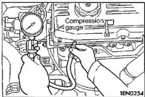
(6) Set compression gauge to one of the spark plug holes.
(7) Crank the engine with the throttle valve fully open and measure the compression pressure.
Standard value (at engine speed of 250–400 r/min.): 1400 kPa (14.0 kg/cm², 199 psi)
Limit (at engine speed of 250–400 r/min.): min. 1000 kPa (10.0 kg/cm², 142 psi)
(8) Measure the compression pressure for all the cylinders, and check that the pressure differences of the cylinders are below the limit.
Limit: max. 100 kPa (1.0 kg/cm², 14 psi)
(9) If there is a cylinder with compression or a compression difference that is outside the limit, pour a small amount of engine oil through the spark plug hole, and repeat the operations in steps (7) and (8).
① If the compression increases after oil is added, the cause of the malfunction is a worn or damaged piston ring and/or cylinder inner surface.
② If the compression does not rise after oil is added, the cause is a burnt or defective valve seat, or pressure is leaking from the gasket.
(10)Connect the distributor connector.
(11) Install the spark plugs and spark plug cables.
(12) Use the multi-use tester (MUT) or MUT-II to erase the self-diagnosis codes.
NOTE
This will erase the problem code resulting from the distributor connector being disconnected.
MANIFOLD VACUUM INSPECTION
E11FW8D
(1) The vehicle should be repaired as follows before the inspection.
- Engine coolant temperature: 80–95°C (176–203°F)
● Lamps, electric cooling fan, and accessories: OFF
● Transmission: Neutral
(2) Connect the multi-use tester (MUT) or MUT-II.
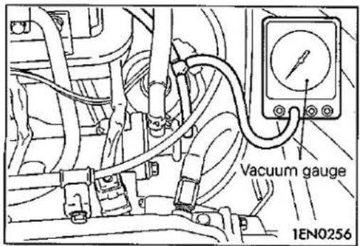
(3) Disconnect the vacuum hose from the nipple for taking off fuel pressure regulator vacuum from the air intake plenum.
(4) Connect a three-way joint between the removed vacuum hose and the nipple and connect a vacuum gauge to the joint.
(5) Start the engine and check that idle speed is within the standard value range.
(6) Check the manifold vacuum.
Standard value: Approx. 71 kPa (530 mmHg, 21 in.Hg)
natural_image
Mechanical assembly diagram showing belt drive system with pulleys and gears (no text or labels)TIMING BELT TENSION ADJUSTMENT
E11FFAP
The timing belt has an automatic tension adjusting mechanism. Adjustment can be made by the following procedure.
(1) Remove the water pump pulley.
(2) Remove the air conditioner pulley bracket.
natural_image
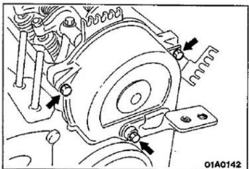
Mechanical assembly diagram showing a motor and gear assembly with no visible text or symbols(3) Remove the timing belt upper cover.
(4) Remove the timing belt lower cover.
(5) Remove the spark plugs.
(6) Turn the crankshaft clockwise to check that the timing belt is okay over its entire length.
Caution
Always turn the crankshaft clockwise.
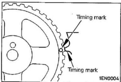
(7) Turn the crankshaft clockwise to bring the No. 1 cylinder piston to the top dead centre on the compression stroke.
Caution
For aligning the timing marks, never turn the crankshaft counterclockwise as it could cause inadequate belt tensioning.
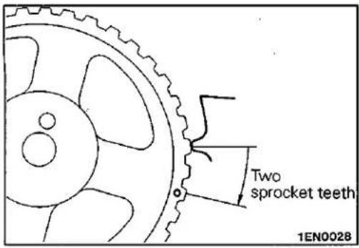
(8) Loosen both pivot side and slot side tensioner bolts and tension the belt, making use of the tensioner spring force.
(9) Turn the crankshaft clockwise by two sprocket teeth (18°).
natural_image
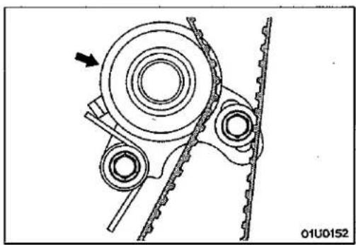
Mechanical gear assembly diagram showing chain and gear components (no text or labels)(10) Push the timing belt tensioner in the direction of the arrow to check that each sprocket is kept in firm and complete engagement with the belt cogs.
After this check, release hand pressure so that only the tensioner spring acts on belt and tighten the slot side bolt and then the pivot side bolt to fix the tensioner in position.
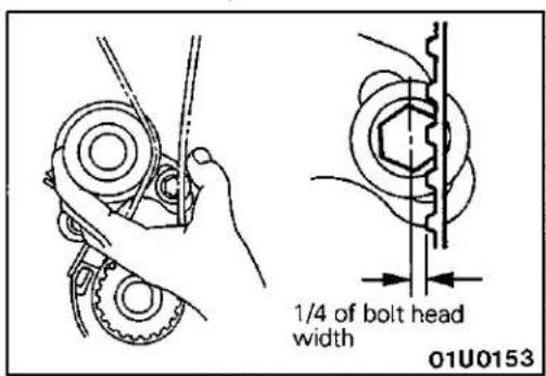
(11) Check the timing belt tension.
Hold the timing belt tensioner and timing belt together by hand and give the belt a slight thumb pressure at a point level with tensioner centre. Make sure that the belt cog crest deflects approximately 1/4 of the tensioner attaching bolt head width.
(12) Install the spark plugs.
(13) Install the timing belt lower cover.
(14) Install the timing belt upper cover.
(15) Install the air conditioner pulley bracket.
(16) Install the water pump pulley and adjust the drive belt deflection.
CRANKSHAFT PULLEY REMOVAL AND INSTALLATION
E1:LA--
Pre-removal and Installation Operation
- Removal and Installation of Under Cover
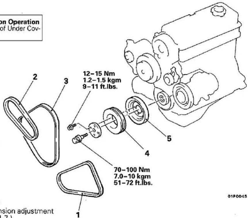
Removal steps
- Drive belt tension adjustment (Refer to P.11-7.)
- Drive belt (Air conditioner)
- Drive belt (Power steering)
- Drive belt (Alternator)
- Crankshaft compressor pulley (Air conditioner)
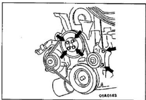
- Crankshaft pulley.
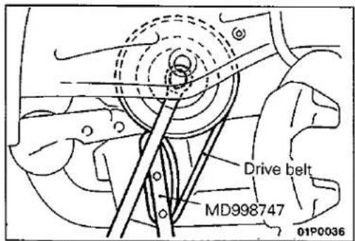
SERVICE POINTS OF REMOVAL AND INSTALLATION E11LEAA
-
REMOVAL AND INSTALLATION OF CRANKSHAFT COMPRESSOR PULLEY / 5. CRANKSHAFT PULLEY Caution
-
This drive belt will get damaged. Do Not use the engine's drive belt.
- Never use a damaged drive belt.
CAMSHAFT AND CAMSHAFT OIL SEAL
E11HA--
REMOVAL AND INSTALLATION
Pre-removal and Post-installation Operation
- Removal and Installation of Timing Belt (Refer to P.11-28.)
- Removal and Installation of Distributor (Refer to GROUP 16 – Distributor)
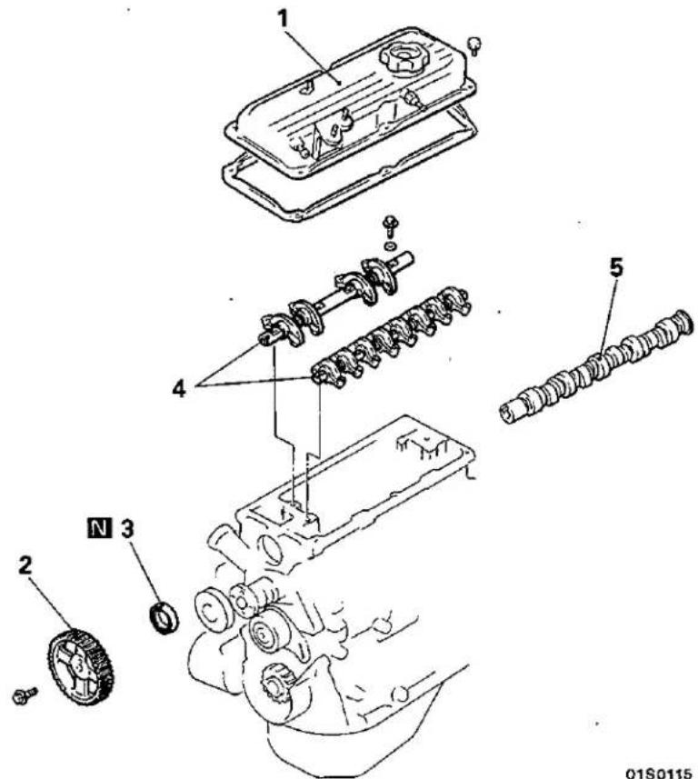
Removal steps

- Rocker cover
- Camshaft sprocket
- Oil seal
- Valve clearance inspection and adjustment (Refer to P.11-9.)
- Rocker arm assembly
- Camshaft

01\$0115
SERVICE POINTS OF REMOVAL
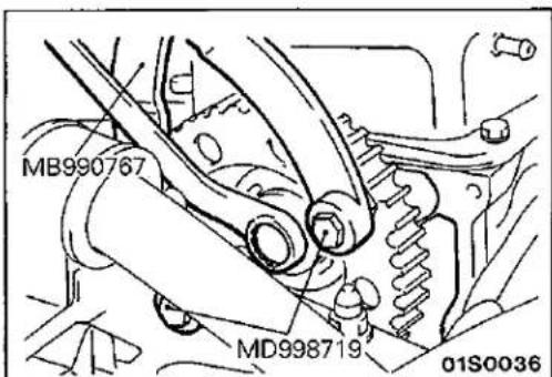
2. REMOVAL OF CAMSHAFT SPROCKET
E11HBAO
SERVICE POINTS OF INSTALLATION
E11HCAP
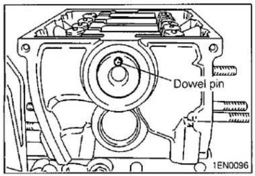
5. INSTALLATION OF CAMSHAFT
(1) Position the dowel pin of the camshaft as shown in the illustration.
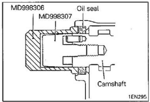
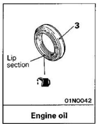
3. INSTALLATION OF OIL SEAL
(1) Install the special tool, Guide on the camshaft.
(2) Apply oil to the oil seal and insert the oil seal along the Guide until it contacts the cylinder head.
(3) Using the special tool, Installer, press-fit the oil seal into the cylinder head.
OIL PAN
E11KA--
REMOVAL AND INSTALLATION
Pre-removal and Post-installation Operation
- Draining and Supplying of Engine Oil
- Removal and Installation of Oil Level Gauge
- Removal and Installation of Front Exhaust Pipe (Refer to GROUP 15 – Exhaust Pipe and Muffler.)
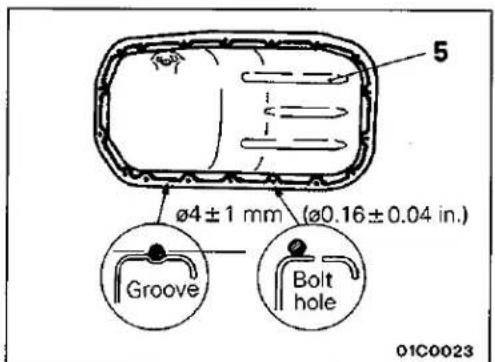
Specified sealant: MITSUBISHI GENUINE PART No. MD997110 or equivalent
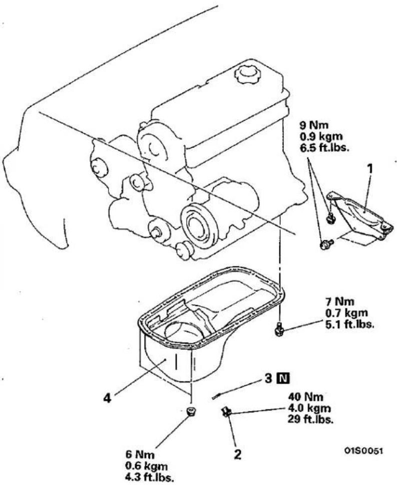
Removal steps

- Bell housing cover
- Drain plug
- Gasket
- Oil pan
© Mitsubishi Motors Corporation
Dec. 1991
SERVICE POINTS OF REMOVAL
E11KBBP
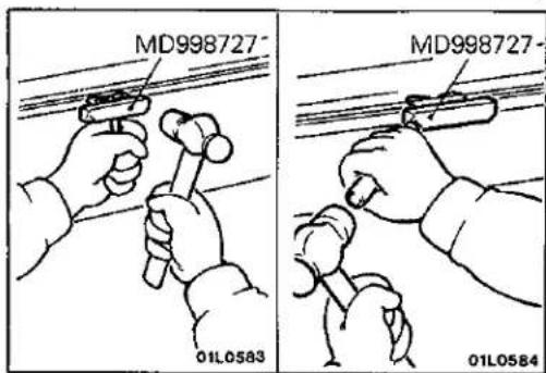
4. REMOVAL OF OIL PAN
After removing the oil pan mounting bolts, remove the oil pan with the special tool and a brass bar.
Caution
Perform this slowly to avoid deformation of the oil pan flange.
SERVICE POINTS OF INSTALLATION
E11KDBN
4. INSTALLATION OF OIL PAN
Caution
After cleaning the oil pan mounting bolt holes in the oil seal case, the oil pan should be installed.
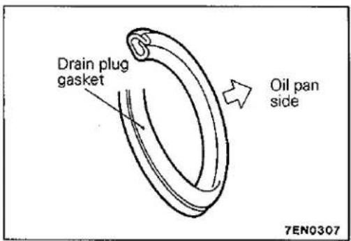
2. INSTALLATION OF GASKET
Replace the gasket with a new gasket, and install it in the direction shown in the illustration.
CRANKSHAFT OIL SEAL REMOVAL AND INSTALLATION
E11UA--
Pre-removal and Post-installation Operation
- Removal and Installation of Timing Belt (Refer to P.11-28.)
● Removal and Installation of Oil Pan (Refer to P.11-20.)
- Removal and Installation of Transmission Assembly (Refer to GROUP 22 or 23 – Transmission Assembly.)
- Removal and Installation of Clutch Cover and Disc
Engine oil
Engine oil
01\$0110
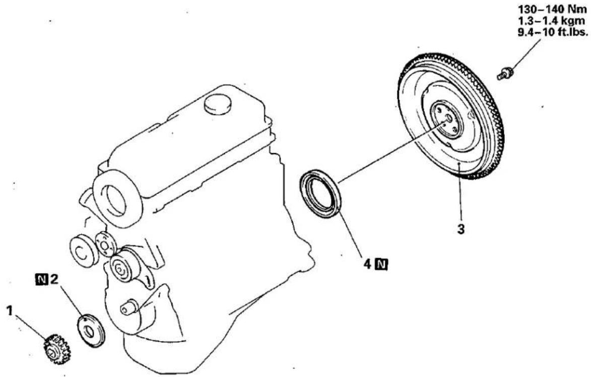
Removal steps of crankshaft front oil seal
- Crankshaft sprocket
- Crankshaft front oil seal
Removal steps of crankshaft rear oil seal
SERVICE POINTS OF REMOVAL
E11UBAF
3. REMOVAL OF FLYWHEEL ASSEMBLY OR DRIVE PLATE
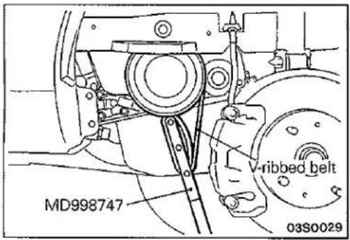
(1) Fix the crank shaft pulley by using the V-ribbed belt and the special tool.
Caution
(1) Because the V-ribbed belt installed in the vehicle may be damaged, use a disused V-ribbed belt.
(2) Do not use a damaged V-ribbed belt.
(2) Remove the flywheel assembly
SERVICE POINTS OF INSTALLATION
E11UCAL
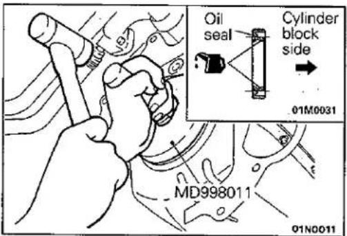
4. INSTALLATION OF CRANKSHAFT REAR OIL SEAL
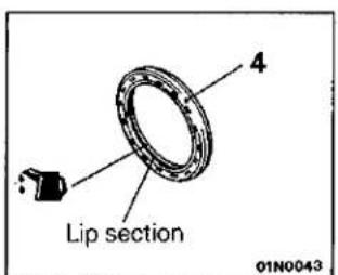
(1) Apply a small amount of engine oil to the entire circumference of the oil seal lip.
(2) Tap the oil seal as shown in the illustration until it is flush with the oil seal case.
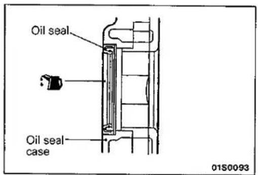
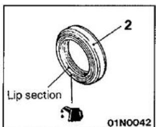
2. INSTALLATION OF CRANKSHAFT FRONT OIL SEAL
(1) Apply a small amount of engine oil to the entire circumference of the oil seal lip.
(2) Tap the oil seal until it is flush with the oil seal case.
CYLINDER HEAD GASKET
REMOVAL AND INSTALLATION
E11JA--
Pre-removal Operation
- Reduce the Inner Pressure of Fuel Line and Hose (Refer to GROUP 13 – Service Adjustment Procedures.)
- Draining the Engine Coolant
- Draining the Engine Oil
- Removal of Air Intake Hose (Refer to GROUP 15 – Air Cleaner.)
Post-installation Operation
- Installation of Air Intake Hose (Refer to GROUP 15 – Air Cleaner.)
• Refilling the Engine Oil
• Refilling the Engine Coolant - Adjusting the Accelerator Cable (Refer to GROUP 13 – Service Adjustment Procedures.)
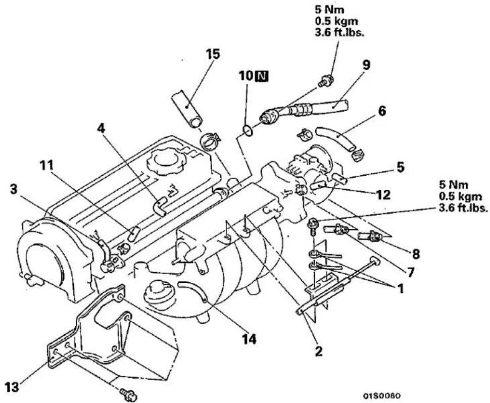
Removal steps
- Earth cable connection
- Accelerator cable connection
- PCV hose connection
- Breather hose connection
- Vacuum hose connection
- Water hose connection (Throttle body → thermostat housing)
- Water hose connection (Throttle body → water inlet pipe)
- Water hose connection (Heater unit → thermostat housing)
- High-pressure hose connection
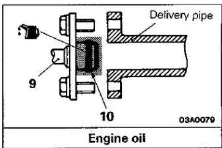
- O-ring
- Return hose connection
- Brake booster vacuum hose connection
- Engine mounting stay
- Vacuum hose
- Radiator upper hose
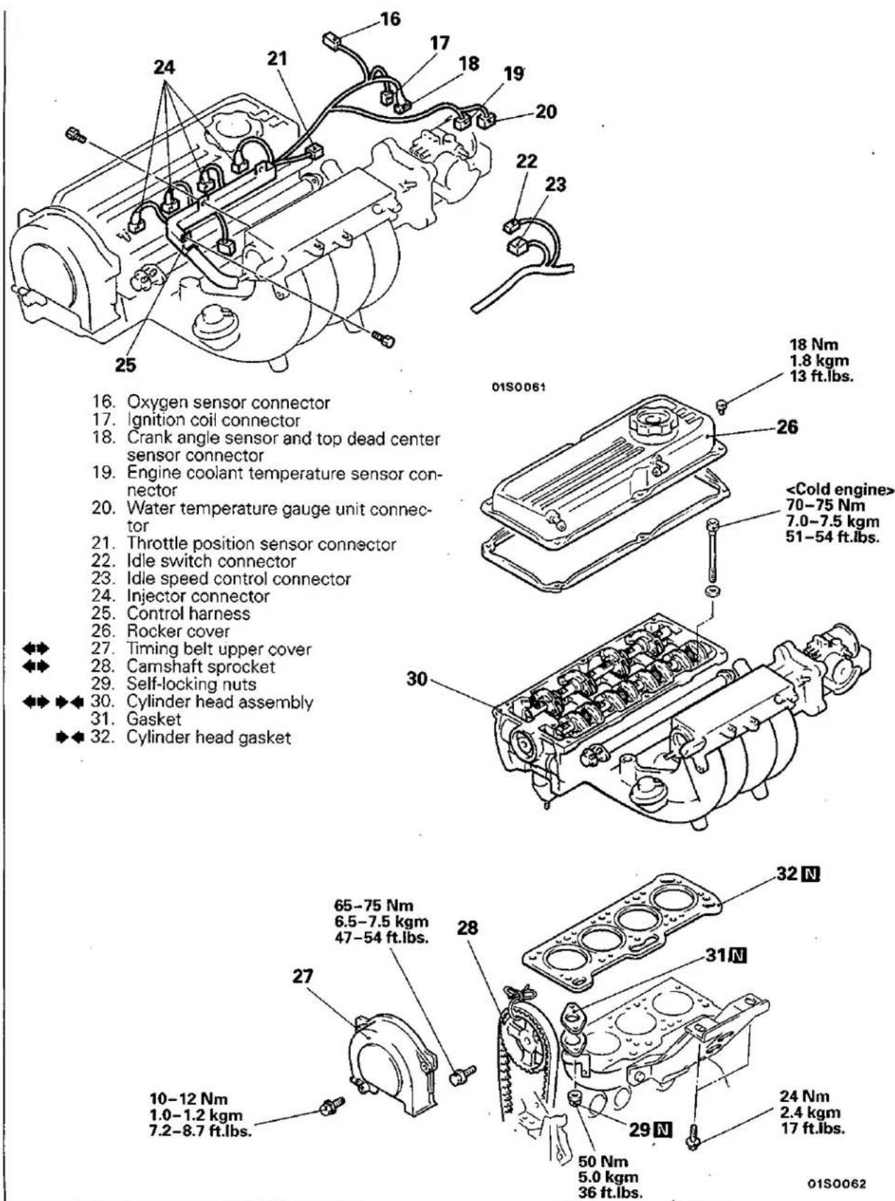
16. Oxygen sensor connector
17. Ignition coil connector
18. Crank angle sensor and top dead center sensor connector
19. Engine coolant temperature sensor connector
20. Water temperature gauge unit connector
21. Throttle position sensor connector
22. Idle switch connector
23. Idle speed control connector
24. Injector connector
25. Control harness
26. Rocker cover
27. Timing belt upper cover
28. Camshaft sprocket
29. Self-locking nuts
30. Cylinder head assembly
31. Gasket
32. Cylinder head gasket
SERVICE POINTS OF REMOVAL
E11JBBD
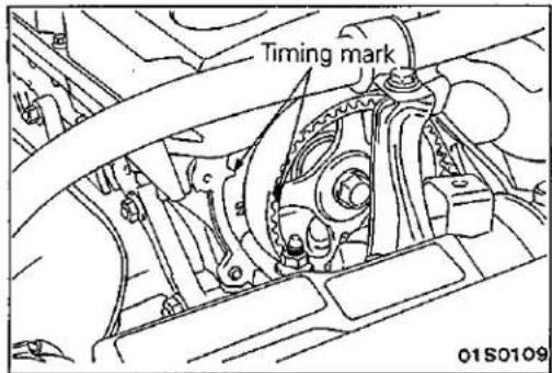
27. REMOVAL OF TIMING BELT UPPER COVER
After removing the timing belt upper cover, rotate the crankshaft clockwise and align the timing marks.
Caution
The crankshaft must always be rotated clockwise.
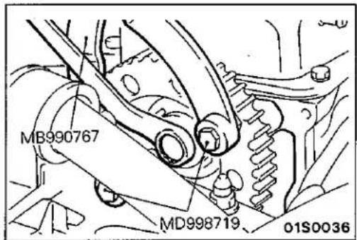
28. REMOVAL OF CAMSHAFT SPROCKET
(1) Use the special tool to remove the camshaft sprocket with the timing belt attached.
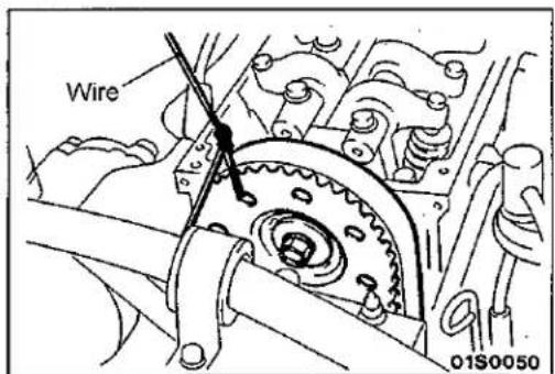
(2) Tie the camshaft sprocket and timing belt with a wire so that the position of the camshaft sprocket will not move with respect to the timing belt.
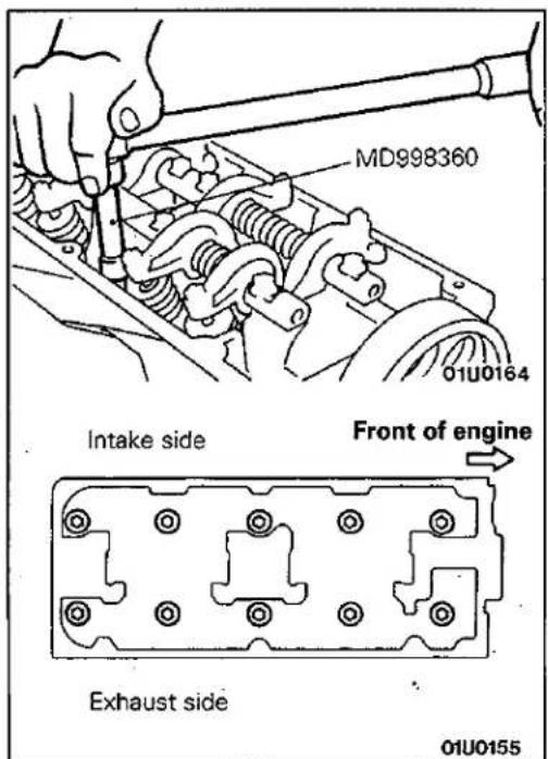
30. REMOVAL OF CYLINDER HEAD ASSEMBLY
Using the special tool, loosen the bolts in the order shown in the illustration (in 2 or 3 cycles), remove them and then remove the cylinder head assembly.
natural_image
Line drawing of an engine cylinder head with a hand pointing to the inner cylinder (no text or symbols)SERVICE POINTS OF INSTALLATION
E11JDCY
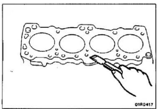
32. INSTALLATION OF CYLINDER HEAD GASKET
(1) Use a scraper to remove the cylinder head gasket from the cylinder block.
Caution
Take care that no foreign material gets into the cylinder, or into the engine coolant or oil passages.
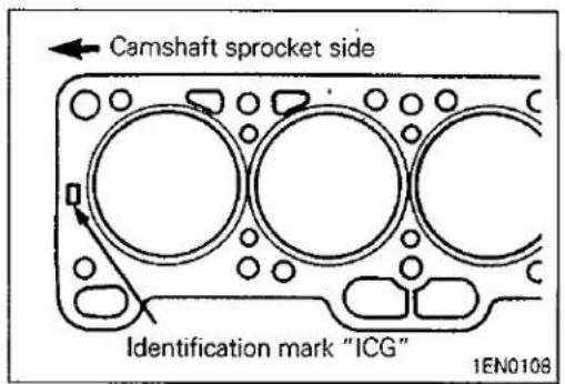
(2) Place the cylinder head gasket on the cylinder block with the marks facing upward.
30. INSTALLATION OF CYLINDER HEAD ASSEMBLY
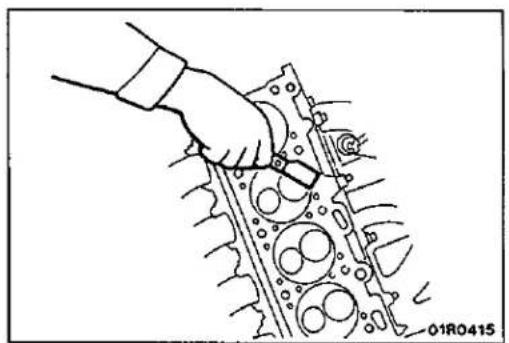
(1) Use a scraper to remove the cylinder head gasket from the cylinder head assembly.
Caution
Take care that no foreign material gets into the engine coolant or oil passages.
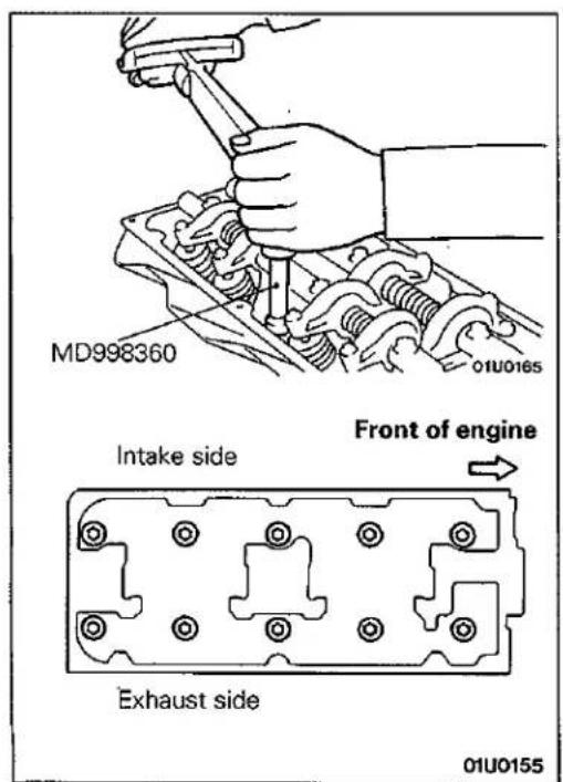
(2) Using the special tool, tighten the bolts in the order shown repeating the sequence once or twice.
TIMING BELT
E11GA--
REMOVAL AND INSTALLATION
Pre-removal and post-installation Operation
- Removal and Installation of Under Cover
- Removal and Installation of Crankshaft Pulley (Refer to P.11-17.)
- Removal and Installation of Engine Mount (Refer to GROUP 32 – Engine Mount.)
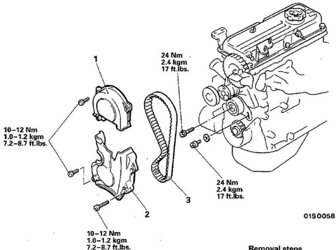

Removal steps
- Timing belt upper cover
- Timing belt lower cover
- Timing belt
© Mitsubishi Motors Corporation
Dec. 1991
SERVICE POINTS OF REMOVAL
E11GBGC
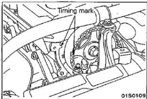
1. REMOVAL OF TIMING BELT UPPER COVER
After removing the timing belt upper cover, rotate the crankshaft clockwise and align the timing marks.
Caution
The crankshaft should always be turned only clockwise.
PWME9117
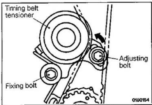
3. REMOVAL OF TIMING BELT
(1) Loosen the timing belt tensioner bolts.
(2) Move the timing belt tensioner to the water pump side and temporarily tighten the bolt so that the tensioner doesn't return.
(3) Remove the timing belt.
Caution
If the timing belt is to be re-used, use chalk to mark (on its flat side) an arrow indicating the clockwise direction.
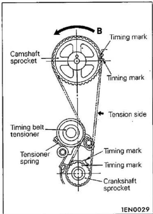
SERVICE POINTS OF INSTALLATION
E11GDGC
3. INSTALLATION OF TIMING BELT
(1) Align the timing marks on the camshaft sprocket and crankshaft sprocket. (Now the piston in No. 1 cylinder is at the top dead centre on the compression stroke.)
(2) Set the timing belt first on crankshaft sprocket and then keeping the tension side of belt tight, set on the camshaft sprocket.
If the timing belt is re-used, install so that the arrow marked on it at time of removal is pointing in the clockwise direction.
(3) Apply counterclockwise force (in the direction B) to the camshaft sprocket to give tension to the belt on tension side and make sure that all timing marks are lined up.
(4) Install the crankshaft pulley temporarily. This is to prevent the belt from coming off when crankshaft is turned.
Caution
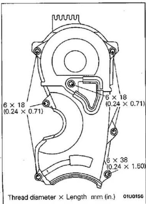
2. INSTALLATION OF TIMING BELT LOWER COVER/ 1. TIMING BELT UPPER COVER
Note that the timing belt lower and upper cover attaching bolts differ in size from one place to another.
ENGINE ASSEMBLY
REMOVAL AND INSTALLATION
E11TA--
Pre-removal Operation
- Releasing of Fuel Line Pressure (Refer to GROUP 13 – Service Adjustment Procedures.)
• Removal of the Hood - Draining of the Coolant (Refer to GROUP 14 – Service Adjustment Procedures.)
- Removal of the Transmission Assembly (Refer to GROUP 22, 23 – Transmission Assembly.)
- Removal of the Radiator (Refer to GROUP 14 – Radiator.)
Post-installation Operation
- Installation of the Radiator (Refer to GROUP 14 – Radiator.)
- Installation of the Transmission Assembly (Refer to GROUP 22, 23 – Transmission Assembly.)
- Supplying of the Coolant (Refer to GROUP 14 – Service Adjustment Procedures.)
• Installation of the Hood - Accelerator Cable Adjustment (Refer to GROUP 13 – Service Adjustment Procedures.)
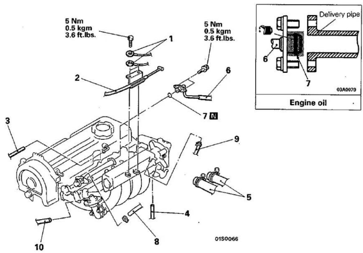
Removal steps
- Earth cable connection
- Accelerator cable connection
- Breather hose connection
- Vacuum hose connection
- Heater hose connection
- High-pressure hose connection
- O-ring
- Return hose connection
- Brake booster vacuum hose connection
- Vacuum hose connection
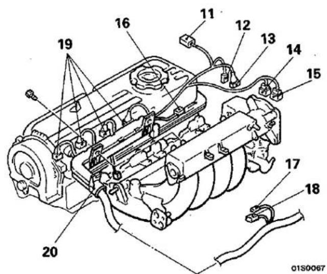
- Oxygen sensor connector
- Ignition coil connector
- Crank angle sensor and top dead center sensor connector
- Engine coolant temperature sensor connector
- Water temperature gauge unit connector
- Throttle position sensor connector
- Idle switch connector
- Idle speed control connector
- Injector connector
-
Control harness
-
Alternator connector
-
Power steering oil pressure switch connector
- Adjustment of V-ribbed belts (Refer to P.11-7.)
- V-ribbed belt for air conditioner
- Air conditioner compressor
- V-ribbed belt for power steering
- Power steering oil pump


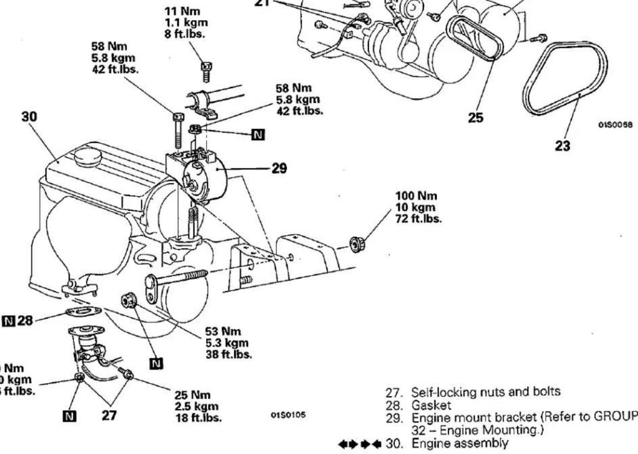
natural_image
Technical line drawing of a mechanical assembly with no visible text or symbols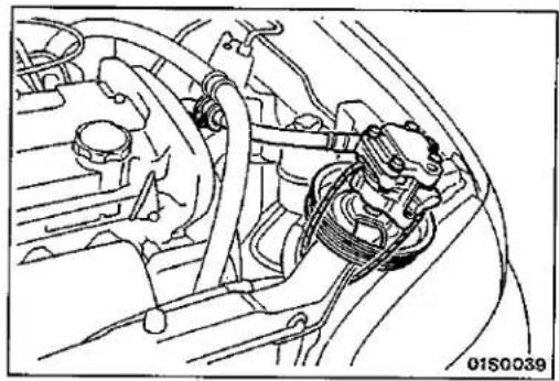
natural_image
Technical line drawing of a car engine bay with hoses and suspension components (no text or symbols)SERVICE POINTS OF REMOVAL
E11TBAQ
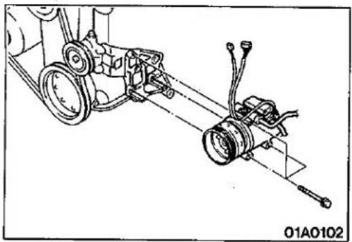
24. REMOVAL OF AIR CONDITIONER COMPRESSOR
Disconnect the air conditioner compressor connector and remove the compressor from the compressor bracket with the hose still attached.
NOTE
Place the removed air conditioner compressor in a place where it will not be a hindrance when removing and installing the engine assembly, and tie it with a cord.
26. REMOVAL OF POWER STEERING OIL PUMP
Remove the power steering oil pump from the bracket with the hose attached.
NOTE
Place the removed power steering oil pump in a place where it will not be a hindrance when removing and installing the engine assembly, and tie it with a cord.
30. REMOVAL OF ENGINE ASSEMBLY
After checking that all cables, hoses and harness connectors, etc., are disconnected from the engine, lift the chain block slowly to remove the engine assembly upward from the engine compartment.
SERVICE POINTS OF INSTALLATION
E11TDAS
30. INSTALLATION OF ENGINE ASSEMBLY
Install the engine assembly while checking to be sure that the cables, hoses, and harness connectors are not clamped.
ENGINE <4G9>
SERVICE ADJUSTMENT PROCEDURES
ALTERNATOR DRIVE BELT TENSION INSPECTION AND ADJUSTMENT E11FQBN
ALTERNATOR DRIVE BELT TENSION INSPECTION
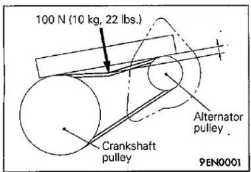
Check the tension by pulling or pushing at the centre of the belt between pulleys with a force of 100 N (10 kg, 22 lbs.) as shown in the figure.
Measure drive belt deflection amount.
Standard value: 8.5–12 mm (0.34–0.47 in.)
ALTERNATOR DRIVE BELT TENSION ADJUSTMENT
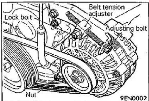
(1) Loosen the nut of the alternator pivot bolt.
(2) Loosen the lock bolt.
(3) Turn the adjusting bolt to adjust the amount of belt deflection to the standard value.
Standard value:
If used belt (with correct tension)
is used 9.5 mm (0.37 in.)
If a new belt is used 7.0–8.5 mm (0.28–0.34 in.)
(4) Tighten the lock bolt.
Tightening torque: 20–25 Nm
(2.0-2.5 kgm, 14-18 ft.lbs.)
(5) Tighten the nut of the alternator pivot bolt.
Tightening torque: 45 Nm (4.5 kgm, 33 ft.lbs.)
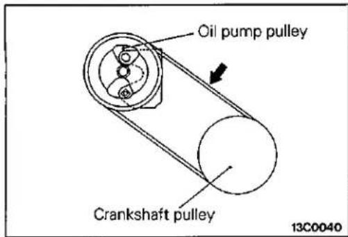
POWER STEERING OIL PUMP DRIVE BELT TEN- SION INSPECTION AND ADJUSTMENT
- Press in the V-ribbed belt at the illustrated position with about 100 N (10 kg, 22 lbs.) and measure deflection. Use a belt tension gauge to check that the belt tension is at the standard value.
Standard value:
| Deflection mm (in.) | Tension N (kg, lbs.) | |
| When belt tension is readjusted | 9.5–11.5(0.374–0.453) | 400–600(40–60, 88–132) |
| When new belt is installed | 7.5–9.0(0.295–0.354) | 650–850(65–85, 143–187) |
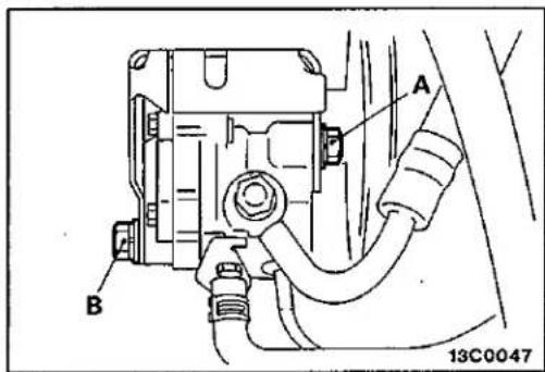
- If the deflection is out of the standard values, adjust the belt tension using the following procedures.
(1) Loosen bolts A and B (for holding the oil pump).
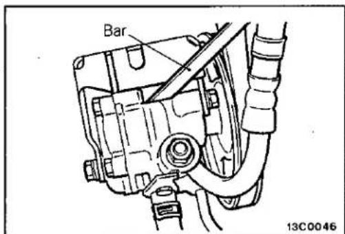
(2) Place a bar or similar object against the body of the oil pump, and, while manually providing the suitable amount of tension, adjust the amount of flexion of the belt.
(3) Tighten bolts A and B in that order.
(4) Check the amount of flexion of the belt; readjust if necessary.
Caution
The check should be made after turning the engine one time or more in the regular direction of rotation (to the right).
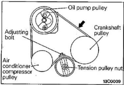
POWER STEERING OIL PUMP AND AIR CONDITIONER COMPRESSOR DRIVE BELT TENSION INSPECTION AND ADJUSTMENT
- Press in the V-ribbed belt at the illustrated position with about 100 N (10 kg, 22 lbs.) and measure deflection. Use a belt tension gauge to check that the belt tension is at the standard value.
Standard value:
| Deflection mm (in.) | Tension N (kg, lbs.) | |
| When belt tension is readjusted | 6.8-7.6(0.268-0.299) | 500-630(50-63, 110-139) |
| When new belt is installed | 5.5-6.0(0.217-0.236) | 750-800(75-80, 165-176) |
- If the deflection is out of the standard values, loosen the tension pulley nut and adjust the belt tension with adjusting bolt.
VALVE CLEARANCE INSPECTION AND ADJUSTMENT <4G92> E11FDBZ
Refer to P.11-9.
Standard value (hot engine):
| Intake valve | 0.20 mm (0.008 in.) |
| Exhaust valve | 0.30 mm (0.012 in.) |
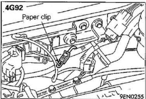
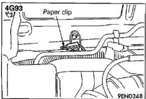
IGNITION TIMING INSPECTION AND ADJUSTMENT E11FUBK
(1) Before inspection and adjustment set vehicle in the following condition.
- Engine coolant temperature: 80–95°C (176–203°F)
- Lamps, electric cooling fan and all accessories: OFF
● Transmission: Neutral (P range on vehicles with A/T)
(2) Insert a paper clip into the 1 pin connector (blue) as shown in the illustration at left.
© Mitsubishi Motors Corporation Dec. 1991
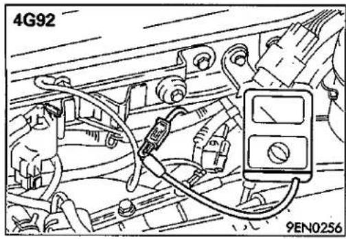
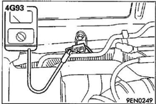
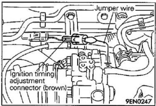
(3) Connect a primary-voltage-detection type of tachometer to the paper clip.
NOTE
Do not use the multi-use tester (MUT) or MUT-II.
If tested with the MUT or MUT-II connected to the diagnosis connector, the ignition timing will not be the basic ignition timing but be ordinary timing.
(4) Set up a timing light.
(5) Start the engine and run at idle.
(6) Check that engine idle speed is within the standard value.
Standard value:
4G92 (Except MVV), 4G93 800 ± 100 r/min
4G92-MVV 700 ± 100 r/min
NOTE
<4G93>
The tachometer indication is a half of actual engine speed.
Therefore, multiply the reading by 2 to know actual engine speed.
(7) Turn the ignition switch to OFF.
(8) Remove the waterproof connector from the ignition timing adjustment connector (brown).
(9) Connect the jumper wire with the clip to the ignition timing adjustment terminal, and earth this to the body as illustrated.
NOTE
Grounding this terminal sets the engine to the basic ignition timing.
(10) Start the engine and run it at idle.
(11) Check that basic ignition timing is within the standard value.
Standard value: 5^ BTDC ± 2^
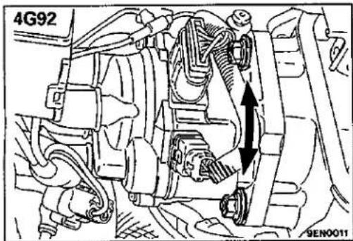
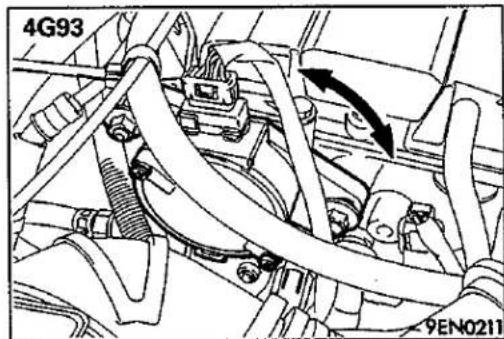
(12) If not within the standard value, loosen distributor <4G92> or crank angle sensor <4G93> fixing nut and adjust by rotating distributor <4G92> or crank angle sensor <4G93> body.
(13) Tighten mounting nut after adjusting.
Tightening torque: 12 Nm (1.2 kg, 9 ft.lbs.)
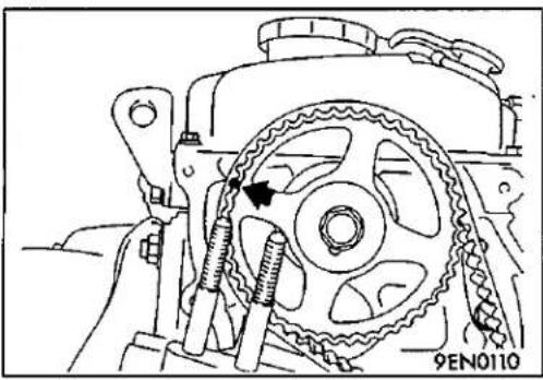
(14) Stop the engine, remove the jumper wire from the ignition timing adjustment connector, (brown), and return the connector to its original condition.
(15) Start the engine and check that ignition timing at the standard value.
Standard value:
4G92 (Except MVV), 4G93
Approx. 8° BTDC
4G92-MVV
Approx. 12° BTDC
NOTE
-
Ignition timing is variable within about ±7^ , even under normal operating.
-
And it is automatically further advanced by about 5° from 8° BTDC (12° BTDC for 4G92-MVV) at higher altitudes.
(16) Sealing tape is to attached to the fixing nut only for vehicles for Switzerland.
NOTE
Sealing tape is attached to all vehicles when new.
IDLE SPEED INSPECTION
E11FXDB
(1) Before inspection and adjustment set vehicles in the following condition.
- Engine coolant temperature: 80–95°C (176–203°F)
• Lamps, electric cooling fan and all accessories: OFF
• Transmission: Neutral (P range on vehicles with A/T)
(2) Check the basic ignition timing. Adjust if necessary.
Standard value: 5° BTDC ±2°
(3) After turning the ignition switch to OFF, connect the multi-use tester (MUT)
For the procedures for connecting the MUT and MUT-II, refer to GROUP 13-Troubleshooting.
(4) Start the engine and run it at idle.
(5) Run the engine at idle for 2 minutes.
(6) Check the idle speed.
Curb idle speed:
4G92 (Except MVV), 4G93 800 ± 100 r/min
4G92-MVV 700 ± 100 r/min
NOTE
The idle speed is adjusted automatically by the idle speed control (ISC) system.
(7) If there is a deviation from the standard value, refer to GROUP 13 - Check Chart Classified by Problem Symptoms, and check the MPI components.
IDLE MIXTURE INSPECTION
(1) Before inspection, set vehicles in the following condition:
- Engine coolant temperature: 80–95°C (176–203°F)
- Lamps, electric cooling fan and all accessories: OFF
• Transmission: Neutral (P range on vehicles with A/T)
(2) Check that the basic ignition timing is within the standard value.
Standard value: 5° BTDC ±2°
(3) After turning the ignition switch to OFF, connect the multi-use tester (MUT)
For the procedures for connecting the MUT and MUT-II, refer to GROUP 13 – Troubleshooting.
(4) Start the engine and run it at 2,500 r/min for 2 minutes.
(5) Set the CO, HC tester
(6) Check the CO concentration and the HC concentration at idle.
Standard value
CO concentration: 0.5% or less
HC concentration: 100 ppm or less
(7) If there is a deviation from the standard value, check the following items:
• Diagnosis output
- Closed-loop control (When the closed-loop control is carried out normally, the output signal of the oxygen sensor changes between 0–400mV and 600–1,000mV at idle.)
• Combustion pressure
- Injector
- Ignition coil, spark plug cable, spark plug
- Leak in the EGR system and in the EGR valve
• Evaporative emission control system
• Compression pressure
NOTE
Replace the three way catalyst when the CO and HC concentrations do not remain inside the standard value, even though the result of the inspection is normal on all items.
COMPRESSION PRESSURE INSPECTION
E11FGAT
Refer to P.11-13.
Standard value (at engine speed of 250–400 r/min.):
4G92 1,450 kPa (14.5 kg/cm², 206 psi)
4G93 1,500 kPa (15.0 kg/cm², 213 psi)
Limit (at engine speed of 250-400 r/min.):
4G92 min. 1100 kPa (11.0 kg/cm², 156 psi)
4G93 min. 1150 kPa (11.5 kg/cm², 164 psi)
MANIFOLD VACUUM INSPECTION
E11FWBE
Refer to P.11-15.
Standard value:
Approx. 67 kPa (500 mmHg, 20 in.Hg)
NOTE
natural_image
Mechanical assembly diagram showing a gear and spring mechanism (no text or symbols)TIMING BELT TENSION ADJUSTMENT
E11FFDL
(1) Remove the timing belt upper cover. <4G92>
(2) Turn the crankshaft clockwise for one turn or more to set the No. 1 cylinder to top dead compression center.
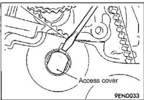
(3) Remove the access cover.
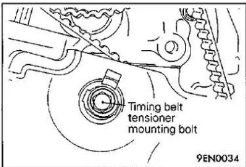
(4) Loosen the timing belt tensioner fixing bolt to apply tension to the belt by means of the force of the tensioner spring.
Caution
The bolt can be loosened 80^-200^ .
If the bolt is loosened more than necessary, the bolt may fall inside the cover.
(5) Tighten the timing belt tensioner fixing bolt.
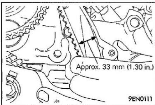
(6) Check that the clearance between the timing belt and the under cover is at the standard value as shown in the illustration.
Standard value: Approx. 33 mm (1.30 in.)
(7) Install the access cover.
(8) Install the timing belt upper cover.
LASH ADJUSTERS CHECK <4G93>
E11FBAO
NOTE
Soon after the engine is started or while it is running, abnormal noise (clattering) which may be attributed to the adjuster sounds but does not stop. In this case, check the following.
(1) Check the engine oil, and refill or replace oil if necessary.
NOTE
- If the oil amount is small, air will be sucked from the oil strainer and mixed in the oil passage.
- If the oil amount is excessive, the oil will be stirred by the crank and mixed with a large amount of air.
- Air and oil can not be separated easily in the deteriorated oil, and the amount of air mixed in the oil increases.
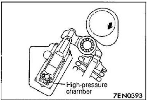
If such mixed-in air enters the high pressure chamber in the lash adjuster, the air in the high-pressure chamber will be compressed while the valve is opened, the lash adjuster will be excessively compressed and abnormal noise will be produced when the valve is closed.
This is the same phenomenon which occurs when the valve clearance is improperly adjusted to be excessively large.
However, it will return to be normal if the air entrapped in the adjuster is released in this case.
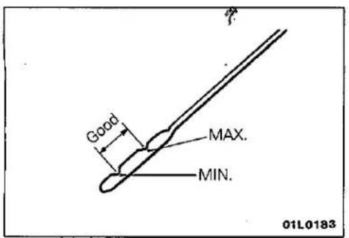
(2) Start the engine, and slowly race* it several times (10 times or less).
If the abnormal noise is eliminated by racing the engine, it means that the air is released from the high-pressure chamber of the lash adjuster and the function of the lash adjuster is returned to normal.
* Gradually increase the engine speed from the idle speed to 3,000 r/min. (for 30 seconds), and then gradually slow down the engine to the idling speed (for 30 seconds).
NOTE
- If the vehicle is parked on a slope for a long time, the oil will be sometimes reduced in the lash adjuster, and air will enter the high-pressure chamber when the engine is started.
- After the vehicle is parked for a long time, the oil will go out of the oil passage. Since it takes a little time to supply oil to the lash adjuster, air sometimes enters the high-pressure chamber.
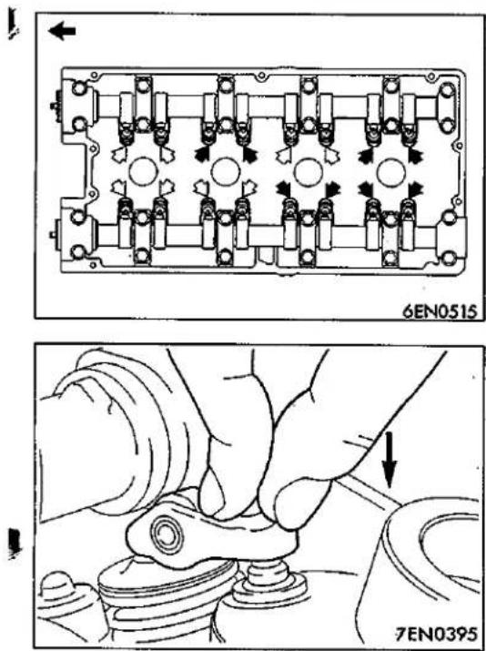
(3) If any abnormal noise is not eliminated by racing, check the lash adjuster.
① Stop the engine.
② Set the engine so that cylinder No. 1 is positioned at the top dead centre of the compression.
③ Press the rocker arm at the area indicated by the ⇌ arrow mark to check whether the rocker arm is lowered or not.
④ Slowly turn the crankshaft 360 degrees clockwise.
⑤ In the same procedure as Step ③, check the rocker arm at the area indicated by the ← arrow mark.
⑥ If the rocker arm can be lowered easily when the part of the rocker arm which is directly above the top of the lash adjuster is pressed, the lash adjuster is defective and should be replaced with a new part.
Furthermore, when replacing the lash adjuster, bleed all of the air from the lash adjuster and then install. After this, check to be sure that there is no abnormality by carrying out the inspection in steps (1) to (5).
NOTE
- A leak-down test can be carried out to accurately determine whether the lash adjuster is defective or not.
- For the procedures for the leak-down test and air bleeding of the lash adjuster, refer to the Engine Workshop Manual.
- Furthermore, if the rocker arm feels extremely stiff and cannot be lowered when it is pressed, the lash adjuster is normal, so investigate for some other cause of the abnormality.
CRANKSHAFT PULLEY
REMOVAL AND INSTALLATION
Pre-removal and Post-installation Operation
- Removal and Installation of Under Cover (L.H.)
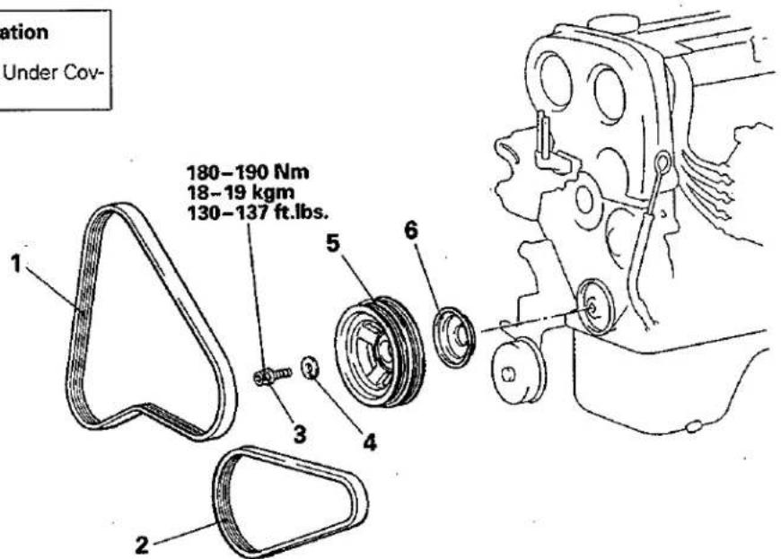
E11LA-
01\$0072
Removal steps

- Drive belt tension adjustment
- Drive belt (Air conditioner)
- Drive belt (Alternator)
- Crankshaft pulley bolt
- Crankshaft pulley washer
- Crankshaft pulley
- Dust cover
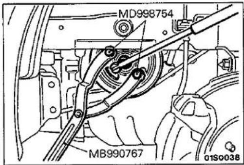
SERVICE POINTS OF REMOVAL
3. REMOVAL OF CRANKSHAFT PULLEY BOLT
E11L83D

SERVICE POINTS OF INSTALLATION
E11LDBE
4. INSTALLATION OF CRANKSHAFT PULLEY WASHER/3. CRANKSHAFT PULLEY BOLT
When installing the crankshaft pulley bolt, install so that the burred side of the crankshaft pulley washer is at the bolt side.

CAMSHAFT AND CAMSHAFT OIL SEAL <4G92>
E11HA-1
REMOVAL AND INSTALLATION
Pre-removal Operation
- Removal of Distributor (Refer to GROUP 16 – Distributor)
- Removal of Timing Belt Cover (Refer to P.11-64.)
Post-installation Operation
- Installation of Distributor (Refer to GROUP 16 - Distributor)
- Installation of Timing Belt Cover (Refer to P.11-64.)
• Engine Adjustment (Refer to P.11-33.)
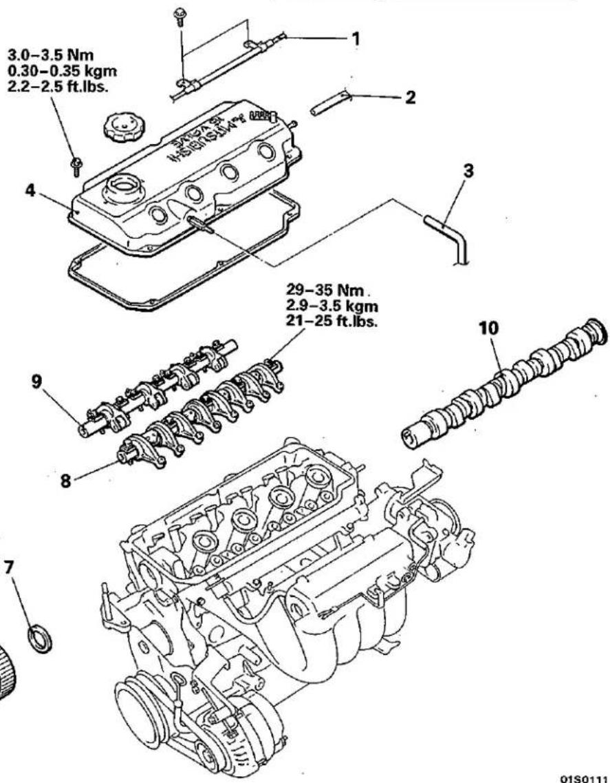
Removal steps


- Accelerator cable connection
- Breather hose connection
- PCV hose connection
- Rocker cover
- Valve clearance adjustment (Refer to P.11-35.)
- Timing belt (Refer to P.11-64.)
- Camshaft sprocket
- Camshaft oil seal
- Rocker arms and rocker arm shaft assembly (Intake side)
- Rocker arms and rocker arm shaft assembly (Exhaust side)
- Camshaft
SERVICE POINTS OF REMOVAL
E11HBAL
6. REMOVAL OF CAMSHAFT SPROCKET
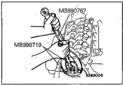
- REMOVAL OF ROCKER ARMS AND ROCKER ARM SHAFT ASSEMBLY (INTAKE SIDE)/9. ROCKER ARMS AND ROCKER ARM SHAFT ASSEMBLY (EXHAUST SIDE) Caution Do not disassemble the rocker arms and rocker arm shaft assembly.
SERVICE POINTS OF INSTALLATION
E11HCAM
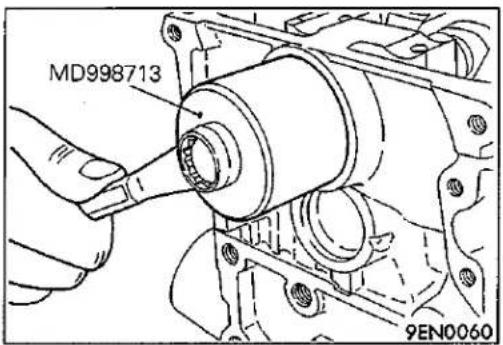
7. INSTALLATION OF CAMSHAFT OIL SEAL
CAMSHAFT AND CAMSHAFT OIL SEAL <4G93>
E11HA-2
REMOVAL AND INSTALLATION
Pre-removal Operation
- Removal of Crank Angle Sensor (Refer to GROUP 16 – Crank Angle Sensor.)
- Removal of Timing Belt Cover (Refer to P.11-69.)
Post-installation Operation
- Installation of Crank Angle Sensor (Refer to GROUP 16 – Crank Angle Sensor.)
- Installation of Timing Belt Cover (Refer to P.11-69.)
- Engine Adjustment (Refer to P.11-33.)
01S0117
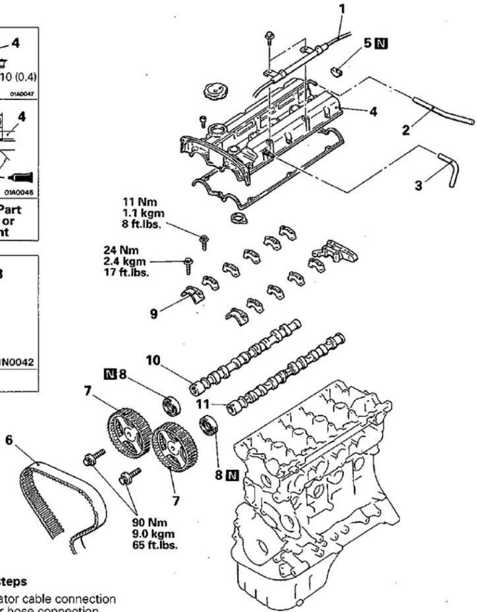
Removal steps
- Accelerator cable connection
- Breather hose connection
- PCV valve hose connection
- Rocker cover
- Semi-circular packing
- Valve clearance adjustment (Refer to P.11-35.)
- Timing belt (Refer to P.11-69.)
-
Camshaft sprocket
-
Camshaft oil seal
- Bearing cap
- Camshaft
- Camshaft
SERVICE POINTS OF REMOVAL
E11HBAO
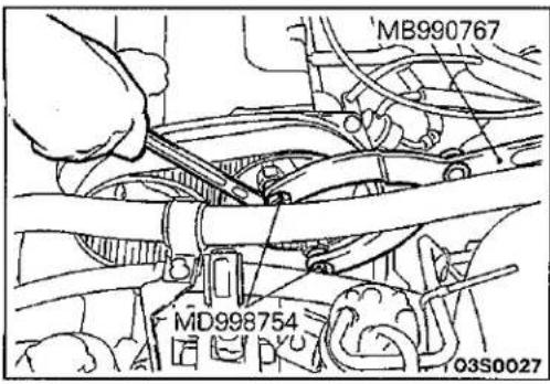
7. REMOVAL OF CAMSHAFT SPROCKET
SERVICE POINTS OF INSTALLATION
E11HCAQ
11. INSTALLATION OF CAMSHAFT
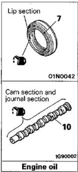
(1) Apply engine oil to journals and cams of the camshafts.
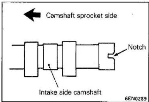
(2) Install the camshafts on the cylinder head. Use care not to confuse the intake camshaft with the exhaust one. The intake camshaft has a notch on its rear end for driving the crank angle sensor.
9. INSTALLATION OF BEARING CAP
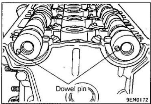
(1) Set the camshaft dowel pins in the positions shown in the illustration.
NOTE
Place the notch for tightening the cam shaft head bolt in the correct position.
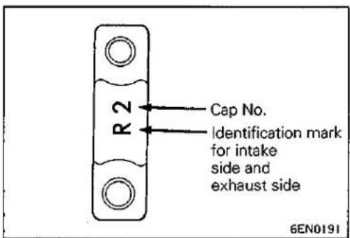
(2) Because bearing caps No. 2 - 5 have the same shape, check the identification mark when installing so as not to mistake the cap number and the intake or exhaust side. Identification marks (embossed on the front and bearing caps nos. 2 - 5.)
L.....Intake side
R.....Exhaust side
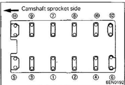
(3) Tighten the bearing caps in the order shown two to three times by torquing progressively.
Tighten to specification in the final sequence.
(4) Check to ensure that the rocker arm is held in position on the lash adjuster and valve stem end.
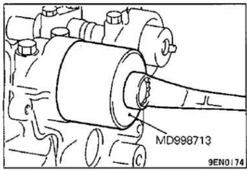
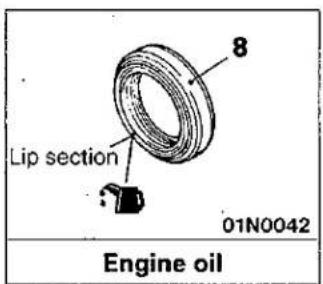
- INSTALLATION OF CAMSHAFT OIL SEAL
OIL PAN
E11KA..
REMOVAL AND INSTALLATION
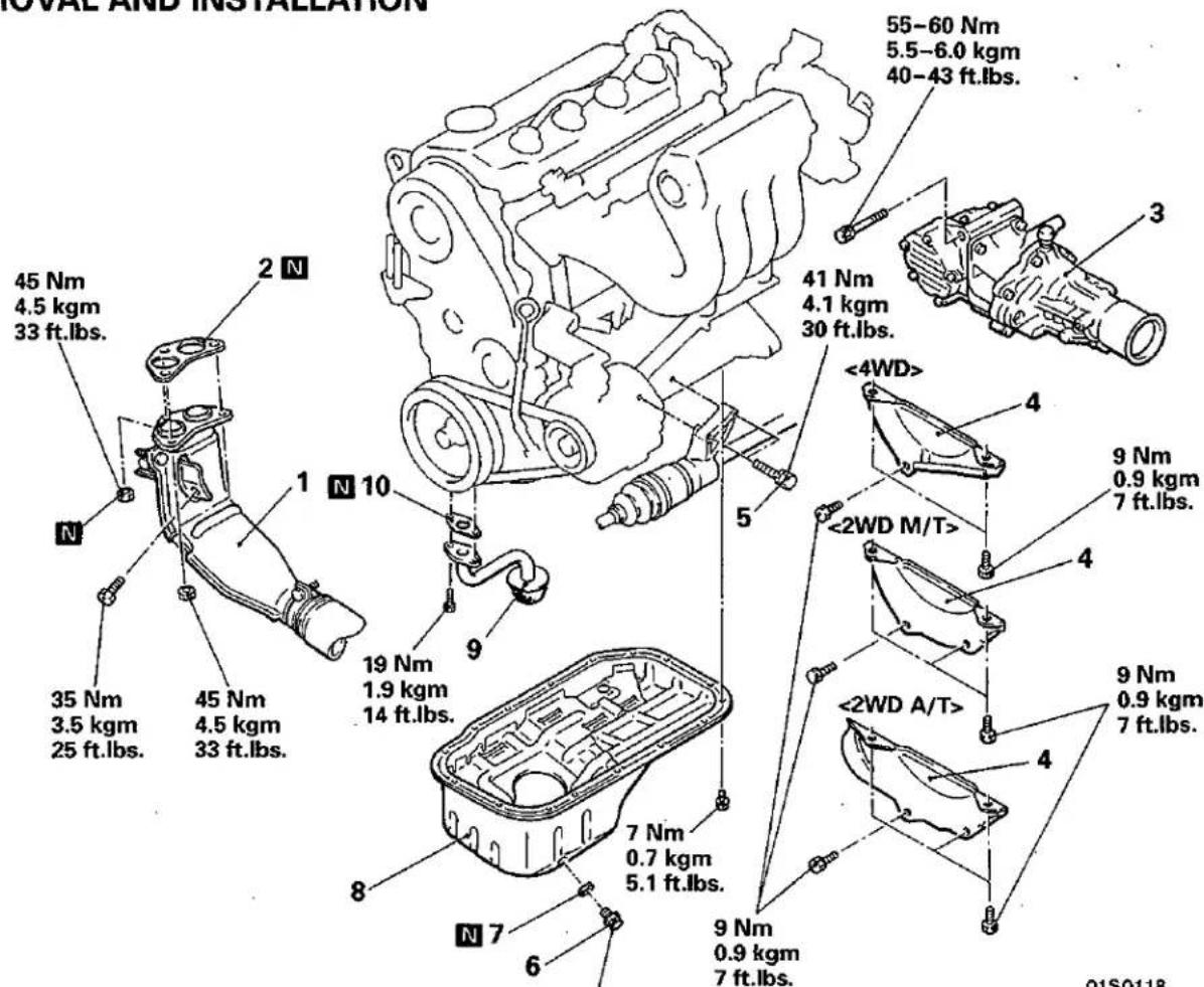
40 Nm 4.0 kgm 29 ft.lbs.
Pre-removal and Post-installation Operation
- Draining and Supplying of Engine Oil (Refer to GROUP 12 – Service Adjustment Procedures.)
- Removal and Installation of Oil Level Gauge
Removal steps
- Front exhaust pipe
- Gasket
- Transfer assembly
- Bell housing cover
- Drive shaft center bearing mounting bolt
- Drain plug
- Drain plug gasket
- Oil pan
- Oil screen assembly
- Gasket
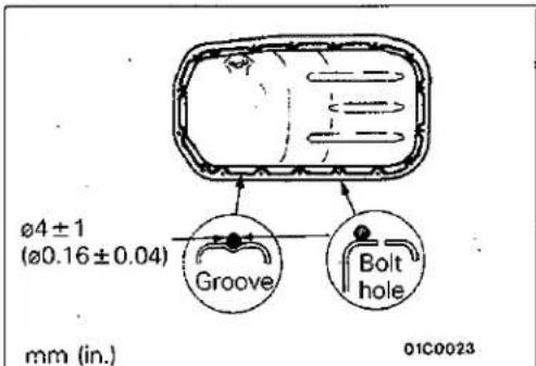
Specified sealant: MITSUBISHI GENUINE PART MD970389 or equivalent
SERVICE POINTS OF REMOVAL
E11KBBM
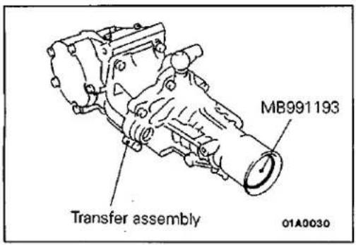
3. REMOVAL OF TRANSFER ASSEMBLY
(1) With the propeller shaft still installed, remove the transfer mounting bolt.
(2) Insert a flat-tipped screwdriver between the transfer and transmission to remove the transfer from the center shaft.
(3) Remove the transfer from the propeller shaft.
Caution
Do not lower the rear end of the transfer, as this will cause the transfer oil to flow out.
(4) After removing the transfer assembly, insert the special tool to prevent transfer oil from flowing out.
(5) Suspend the propeller shaft from the vehicle body with wire, etc.
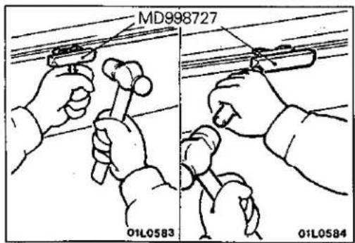
8. REMOVAL OF OIL PAN
After removing the oil pan mounting bolts and nuts, remove the oil pan with the special tool and a brass bar.
Caution
Perform this slowly to avoid deformation of the oil pan flange.
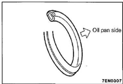
SERVICE POINTS OF INSTALLATION
7. INSTALLATION OF DRAIN PLUG GASKET
Install the drain plug gasket in the direction so that it faces as, shown in the illustration.
CRANKSHAFT OIL SEAL REMOVAL AND INSTALLATION
Pre-removal and Post-installation Operation
- Removal and Installation of Timing Belt (Refer to P.11-64, 69.)
- Removal and Installation of Oil Pan (Refer to P.11-48.)
- Removal and Installation of Transmission Assembly (Refer to GROUP 22 or 23 – Transmission Assembly.)
- Removal and Installation of Clutch Cover and disc
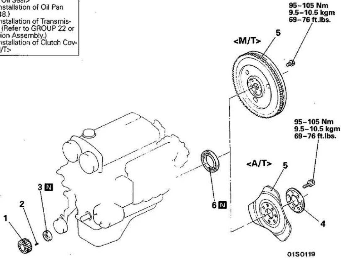
Crankshaft front oil seal removal steps
-
Crankshaft sprocket
-
Key

- Crankshaft front oil seal
Crankshaft rear oil seal removal steps


- Crankshaft rear oil seal
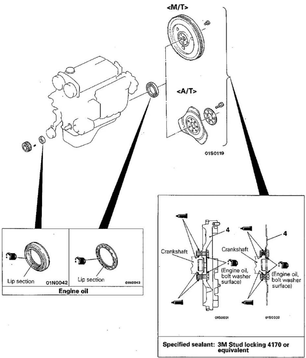
SEALANT AND LUBRICATION POINTS
SERVICE POINTS OF REMOVAL
E11U8AG
5. REMOVAL OF FLYWHEEL ASSEMBLY OR DRIVE PLATE
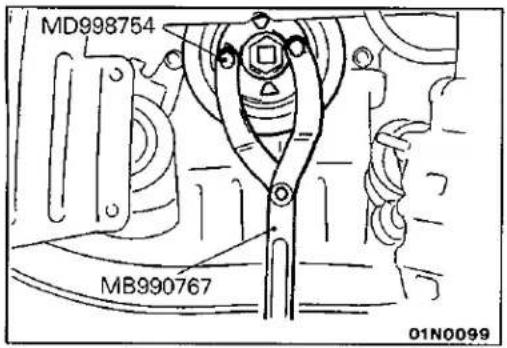
Stop the crankshaft pulley from turning, and remove the flywheel assembly
Caution
(1) Use only the specified special tools, otherwise the damper section of the crankshaft pulley could be damaged.
(2) In order not to damage the timing belt lower cover and front flange, hold the special tool securely so that it doesn't move.
SERVICE POINTS OF INSTALLATION
E11UCAM
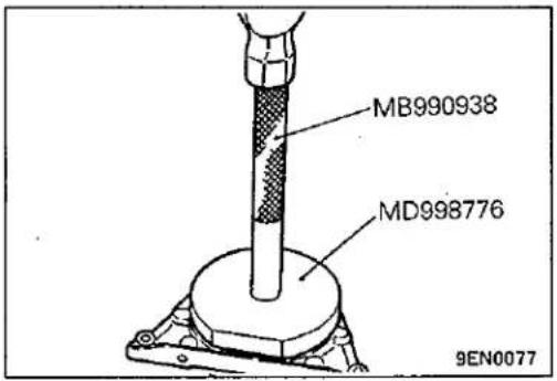
6. INSTALLATION OF CRANKSHAFT REAR OIL SEAL
(1) Apply a small mount of engine oil to the entire circumference of the oil seal lip.
(2) Install the oil seal by tapping it as far as the chamfered position of the oil seal case as shown in the illustration.
5. INSTALLATION OF FLYWHEEL ASSEMBLY OR DRIVE PLATE
(1) Clean the sealant, oil and other particles that are adhering to the mounting bolts, the thread sections of the crankshaft, and the flywheel assembly
(2) Apply oil to the washer surfaces of the flywheel assembly
(3) Apply specified sealant to the thread sections of the mounting bolts.
Specified sealant: 3M Stud locking 4170 or equivalent
(4) Tighten the mounting bolts to the specified torque.
(5) After installation, clean off any sealant adhering to the ends of the flywheel assembly
3. INSTALLATION OF CRANKSHAFT FRONT OIL SEAL
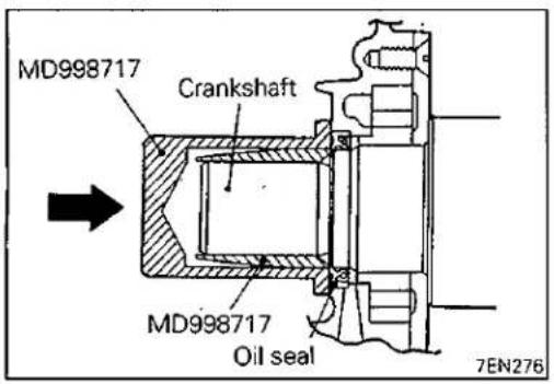
(1) Apply a small amount of engine oil to the entire circumference of the oil seal lip.
(2) Tap the oil seal until it is flush with the oil seal case.
CYLINDER HEAD GASKET <4G92>
REMOVAL AND INSTALLATION
E11JA1
Pre-removal Operation
- Releasing of Fuel Line Pressure (Refer to GROUP 13 – Service Adjustment Procedures.)
- Draining of the Coolant (Refer to GROUP 14 – Service Adjustment Procedures.)
- Draining of the Engine Oil
- Removal of the Air Intake Hose (Refer to GROUP 15 – Air Cleaner.)
Post-installation Operation
- Installation of the Air Intake Hose (Refer to GROUP 15 – Air Cleaner.)
- Supplying of the Coolant (Refer to GROUP 14 – Service Adjustment Procedures.)
• Supplying of the Engine Oil - Accelerator Cable Adjustment (Refer to GROUP 13 – Service Adjustment Procedures.)
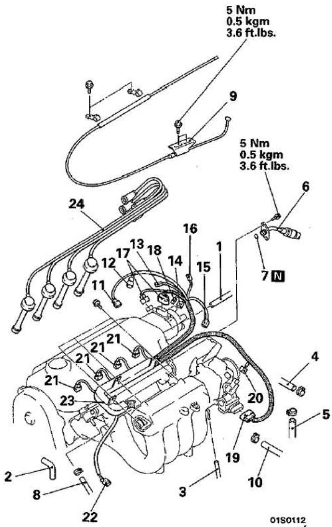
Removal steps
- Breather hose connection
- PCV hose
- Vacuum hose connection
- Water hose connection (Thermostat case → throttle body)
- Water hose connection (Throttle body → water inlet fitting)
- Fuel high pressure hose connection
- O-ring
- Fuel return hose connection
- Accelerator cable connection
- Brake booster vacuum hose connection
- Engine coolant temperature switch connector
- Oxygen sensor connector
- Oil pressure switch connector
- Water temperature gauge unit connector
- Engine coolant temperature sensor connector
- Engine coolant temperature switch connector
- Distributor connector
- Condenser connector
- Idle speed control connector
- TPS connector
- Injector connector.
- Detonation sensor connector
- Control harness assembly
- Spark plug cable
Removal steps
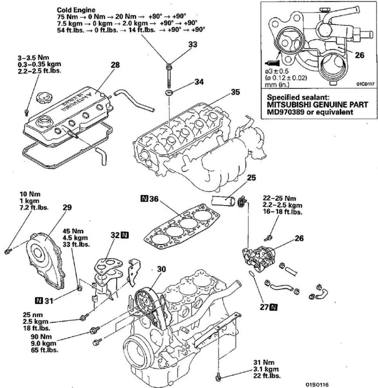
- Connection for radiator upper hose
◆◆ 26. Water inlet fitting, thermostat and thermostat case assembly - O-ring
- Rocker cover
- Timing belt upper cover
- Camshaft sprocket
- Self-locking nuts
- Gasket
- Cylinder head bolt
- Washer
- Cylinder head assembly
- Cylinder head gasket
SERVICE POINTS OF REMOVAL
E11JBAZ
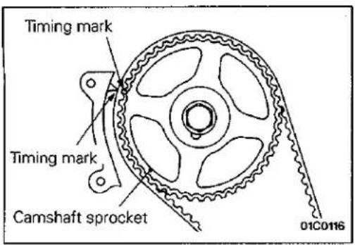
30. REMOVAL OF CAMSHAFT SPROCKET
(1) Rotate the crankshaft in the forward (right) direction and align the timing mark.
Caution
The crankshaft must always be rotated in the forward direction only.
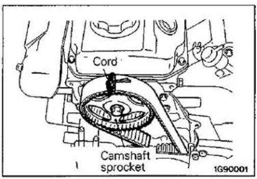
(2) Tie the camshaft sprocket and timing belt with a cord so that the position of the camshaft sprocket will not move with respect to the timing belt.
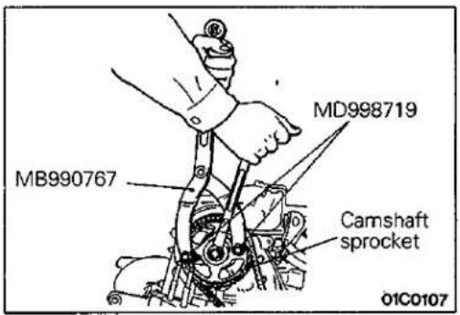
(3) Use the special tool to remove the camshaft sprocket with the timing belt attached.
Caution
After removing the camshaft sprocket, be sure not to rotate the crankshaft.
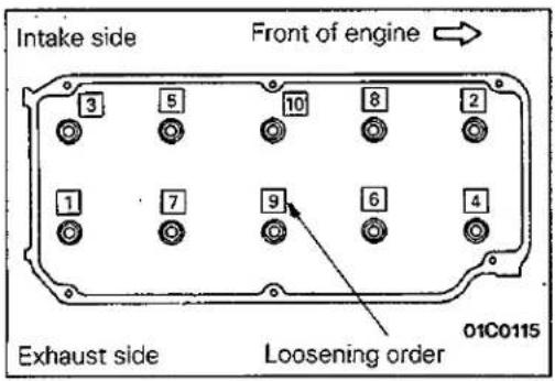
35. REMOVAL OF CYLINDER HEAD ASSEMBLY
Loosen the bolts in 2 or 3 steps in order of the numbers shown in the illustration, and remove the cylinder head assembly.
natural_image
Technical line drawing of an engine cylinder head with a hand pointing to the inner cylinder (no text or symbols present)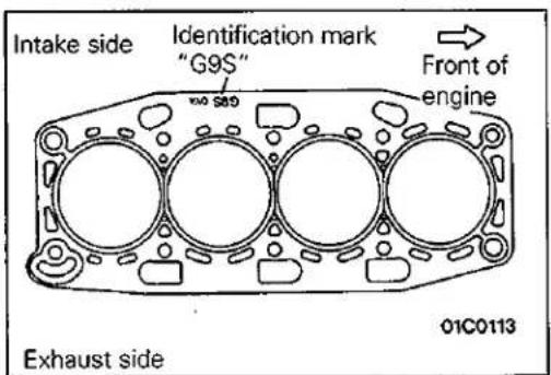
SERVICE POINTS OF INSTALLATION
E11JDCV
36. INSTALLATION OF CYLINDER HEAD GASKET
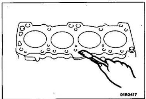
(1) Use a scraper or gasket remover to remove the gasket adhering to the cylinder block.
Caution
When doing this, be careful not to let any foreign substances such as gasket scraps enter the cylinder or the coolant and oil passages.
(2) Place the cylinder head gasket on top of the cylinder block so that the identification mark is facing upwards as in the illustration.
Caution
The cylinder head gasket is easy to mis-install, so be sure to check it. If it is mis-installed, malfunctions such as no oil rising to the cylinder head will occur.
35. INSTALLATION OF CYLINDER HEAD ASSEMBLY/34. WASHER/33. CYLINDER HEAD BOLT
(1) Use a scraper or gasket remover to remove the gasket adhering to the cylinder head assembly.
Caution
When doing this, be careful not to let any foreign substances such as gasket scraps enter the cylinder or the coolant and oil passages.
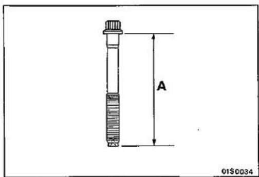
(2) When installing the cylinder head bolts, the length below the head of the bolts should be within the standard value. If it is outside the standard value, replace the bolts.
Limit: Within 96.4 mm (3.795 in.)
(3) Apply a small amount of engine oil to the thread section and the washer of the cylinder head bolt.
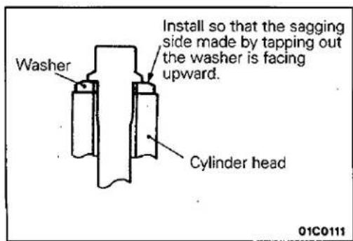
(4) Install so that the sagging side made by tapping out the washer is facing upward.
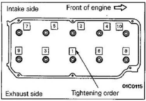
(5) Tighten using the angular tightening method.
| Procedure | Operation contents | Remarks |
| 1↓2↓3↓4↓5 | Tighten to 75 Nm(7.5 kgm, 54 ft.lbs.) | Carry out in the order shown in the illustration. |
| Fully loosen. | Carry out in the reverse order to that shown in the illustration. | |
| Tighten to 20 Nm(2 kgm, 14 ft.lbs.) | Carry out in the order shown in the illustration. | |
| Tighten by 1/4 turn(90°) | Carry out in the ordr shown in the illustration. | |
| Tighten by 1/4 turn(90°) | Carry out in the order shown in the illustration. |
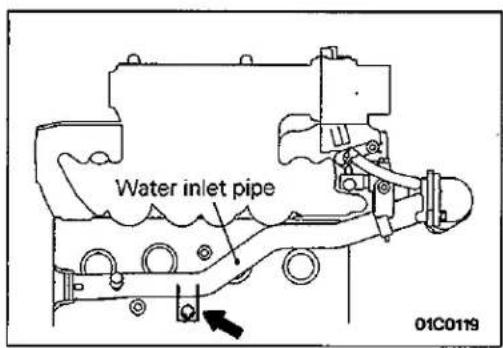
26. INSTALLATION OF WATER INLET FITTING, THERMOSTAT AND THERMOSTAT CASE ASSEMBLY
(1) Loosen the water inlet pipe bolt shown in the illustration.
(2) Apply specified sealant to the thermostat case assembly as shown in the illustration.
Specified sealant: MITSUBISHI GENUINE PART MD970389 or equivalent
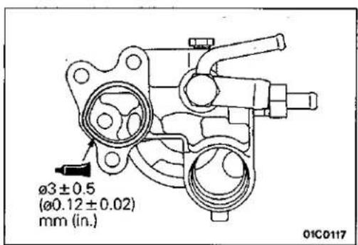
(3) Apply a small amount of water to the O-ring of the water inlet pipe, and press the thermostat case assembly onto the water inlet pipe.
(4) Install the thermostat case assembly mounting bolt.
(5) Tighten the water inlet pipe bolt.
CYLINDER HEAD GASKET <4G93>
E11JA-2
REMOVAL AND INSTALLATION
Pre-removal Operation
- Releasing of Fuel Line Pressure (Refer to GROUP 13 – Service adjustment Procedures.)
- Draining of the Coolant (Refer to GROUP 14 – Service Adjustment Procedures.)
- Draining of the Engine Oil
- Removal of the Air Intake Hose (Refer to GROUP 15 – Air Cleaner.)
- Removal of the Timing Belt (Refer to P.11-69.)
Post-installation Operation
- Installation of the Timing Belt (Refer to P.11-69.)
- Installation of the Air Intake Hose (Refer to GROUP 15 – Air Cleaner.)
- Supplying of the Coolant (Refer to GROUP 14 – Service Adjustment Procedures.)
• Supplying of the Engine Oil - Accelerator Cable Adjustment (Refer to GROUP 13 – Service Adjustment Procedures.)
Removal steps
- Accelerator cable
- Brake booster vacuum hose connection
- Radiator hose connection (upper, lower)
- Breather hose connection
- PCV hose connection
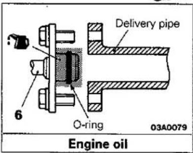
- Fuel high pressure hose connection
- Fuel return hose connection
- Water hose connection
- Heater hose connection
-
Vapour hose connection
-
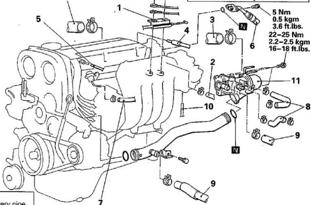
Water inlet fitting, thermostat and thermostat case assembly
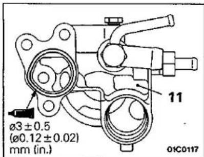
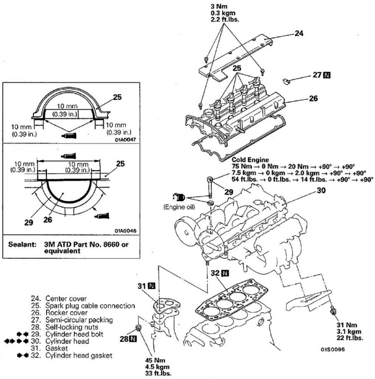
Specified sealant:
MITSUBISHI GENUINE PART
MD970389 or equivalent
01S0084
01S0090
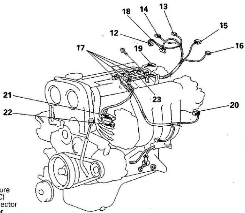
- Engine coolant temperature switch connector (for A/C)
- Oil pressure switch connector
- Oxygen sensor connector
- Engine coolant temperature switch connector
- Water temperature gauge unit connector
- Injector connector
- Crank angle sensor connector
- Throttle position sensor connector
- Idle speed control connector
- Power transistor connector
- Ignition coil connector
- Control harness
© Mitsubishi Motors Corporation Dec. 1991
SERVICE POINTS OF REMOVAL
E11JBAZ
30. REMOVAL OF CYLINDER HEAD ASSEMBLY
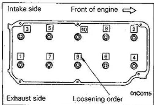
Loosen the bolts in 2 or 3 steps in order of the numbers shown in the illustration, and remove the cylinder head assembly.
PWME9117
natural_image
Line drawing of an engine cylinder head with a hand pointing to the inner cylinder (no text or symbols)SERVICE POINTS OF INSTALLATION
E11JDCV
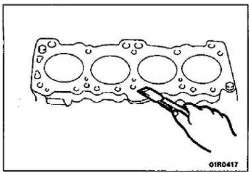
32. INSTALLATION OF CYLINDER HEAD GASKET
(1) Use a scraper or gasket remover to remove the gasket adhering to the cylinder block.
Caution
When doing this, be careful not to let any foreign substances such as gasket scraps enter the cylinder or the coolant and oil passages.
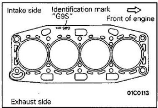
(2) Place the cylinder head gasket on top of the cylinder block so that the identification mark is facing upwards as in the illustration.
Caution
The cylinder head gasket is easy to mis-install, so be sure to check it. If it is mis-installed, malfunctions such as no oil rising to the cylinder head will occur.
√ 30. INSTALLATION OF CYLINDER HEAD ASSEMBLY/29. CYLINDER HEAD BOLT
(1) Use a scraper or gasket remover to remove the gasket adhering to the cylinder head assembly.
Caution
When doing this, be careful not to let any foreign substances such as gasket scraps enter the cylinder or the coolant and oil passages.
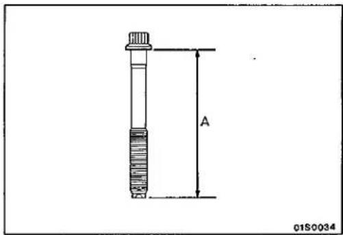
(2) When installing the cylinder head bolts, the length below the head of the bolts should be within the standard value. If it is outside the standard value, replace the bolts.
Limit: Within 96.4 mm (3.795 in.)
(3) Apply a small amount of engine oil to the thread section and the washer of the cylinder head bolt.
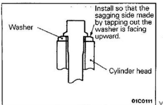
(4) Install so that the sagging side made by tapping out the washer is facing upward.
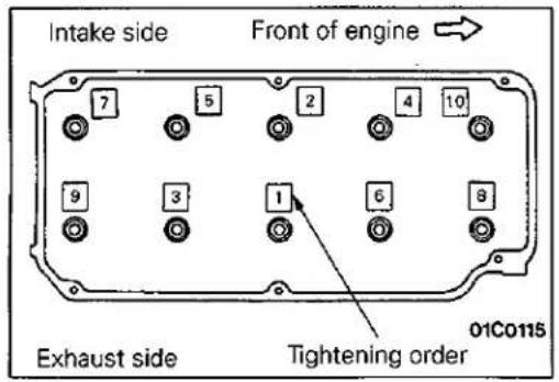
(5) Tighten using the angular tightening method.
| Procedure | Operation contents | Remarks |
| 1↓2↓3↓4↓5 | Tighten to 75 Nm(7.5 kgm, 54 ft.lbs.) | Carry out in the order shown in the illustration. |
| Fully loosen. | Carry out in the reverse order to that shown in the illustration. | |
| Tighten to 20 Nm(2 kgm, 14 ft.lbs.) | Carry out in the order shown in the illustration. | |
| Tighten by 1/4 turn(90°) | Carry out in the ordr shown in the illustration. | |
| Tighten by 1/4 turn(90°) | Carry out in the order shown in the illustration. |
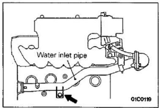
11. INSTALLATION OF WATER INLET FITTING, THERMOSTAT AND THERMOSTAT CASE ASSEMBLY
(1) Loosen the water inlet pipe bolt shown in the illustration.
(2) Apply specified sealant to the thermostat case assembly as shown in the illustration.
Specified sealant: MITSUBISHI GENUINE PART MD970389 or equivalent
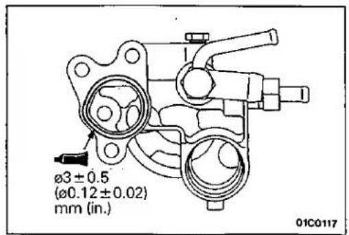
(3) Apply a small amount of water to the O-ring of the water inlet pipe, and press the thermostat case assembly onto the water inlet pipe.
(4) Install the thermostat case assembly mounting bolt.
(5) Tighten the water inlet pipe bolt.
TIMING BELT <4G92>
REMOVAL AND INSTALLATION
E11GA-1
Pre-removal Operation
- Removal of the Under Cover
Post-installation Operation
- Adjustment of Drive Belt Tension (Refer to P.11-33.)
• Installation of the Under Cover
natural_image
Technical line drawing of a mechanical assembly with labeled component 1 (no text or symbols beyond label)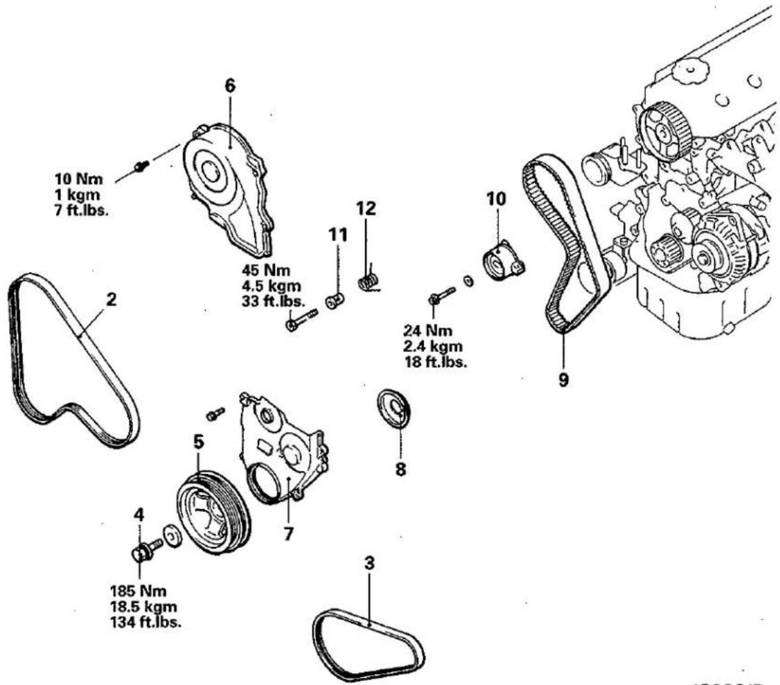
1G90017
Removal steps
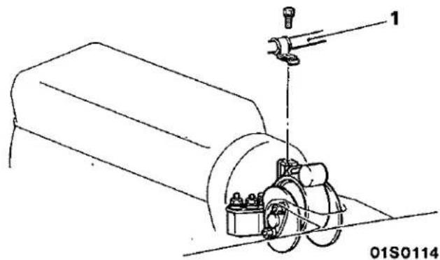
- Clamp section of Air conditioner
- Drive belt (Power steering, Air conditioner)
- Drive belt (Alternator)
- Crankshaft bolt
- Crankshaft pulley
-
Timing belt upper cover
-
Timing belt lower cover
- Flange
Adjustment of timing belt tension - Timing belt
- Timing belt tensioner
- Tensioner spacer
- Tensioner spring

SERVICE POINTS OF REMOVAL
E11GBHA
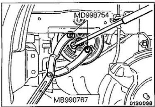
4. REMOVAL OF CRANKSHAFT BOLT/5. CRANKSHAFT PULLEY
Use the special tool to stop the crankshaft pulley from turning, and remove the crankshaft bolt.
Caution
Hold the special tool securely so that it doesn't move.
9. REMOVAL OF TIMING BELT
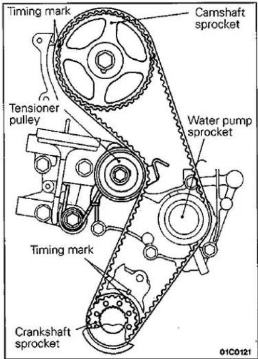
(1) Turn the crankshaft clockwise (right turn) to align each timing mark and to set the No. 1 cylinder at compression top dead centre.
Caution
The crankshaft should always be turned only clockwise.
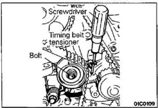
(2) Loosen the timing belt tensioner bolt.
(3) Set a screwdriver to the timing belt tensioner and press it fully back in the direction of the arrow.
(4) Provisionally tighten the timing belt tensioner bolt.
(5) Remove the timing belt.
Caution
If the timing belt is to be re-used, use chalk to mark the flat side of the belt with an arrow indicating the direction of rotation (right turn).
SERVICE POINTS OF INSTALLATION
E11GDHA
9. INSTALLATION OF TIMING BELT
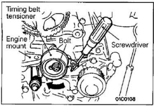
(1) With the timing belt tensioner bolt loosened, use a screwdriver to fully turn the timing belt tensioner as close to the engine mount as possible, and then provisionally tighten the tensioner bolt.
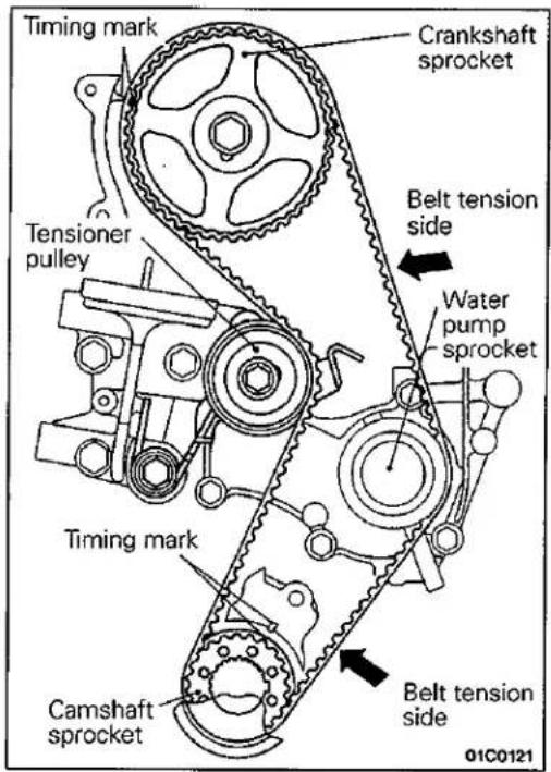
(2) Align each of the camshaft sprocket and the crankshaft sprocket timing marks.
(3) Install the timing belt in the following order, while making sure that the tension side of the belt is not slackened.
① Crankshaft sprocket
② Water pump sprocket
③ Camshaft sprocket
④ Tensioner pulley
Caution
After installing the timing belt, apply force to turn the camshaft sprocket in the reverse direction, and recheck to be sure that the belt is fully tensioned and that each timing mark is in the proper position.
• ADJUSTMENT OF TIMING BELT TENSION
(1) Initially loosen the fixing bolt of the tensioner pulley fixed to the engine mount side by 1/2-1/4 turn, and use the force of the tensioner spring to apply tension to the belt.
(2) Turn the crankshaft in the proper rotation direction (right turn) for two rotations, and recheck to be sure that the timing marks on each sprocket are aligned.
Caution
As the purpose of this procedure is to apply the proper amount of tension to the tension side of the timing belt by using the cam driving torque, turn the crankshaft only by the amount given above. Be sure not to turn the crankshaft in the opposite direction (left turn).
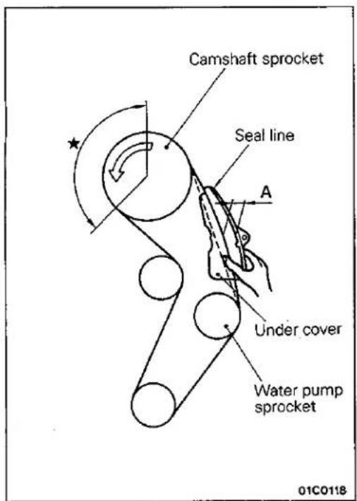
(3) After checking to be sure that no belt teeth in the section marked with ★ are lifted up and that the teeth in each sprocket are engaged, secure the tensioner pulley.
(4) Lastly, lightly clamp the centre of the span between the camshaft sprocket and the water pump sprocket on the belt tension side with your thumb and forefinger as shown in the illustration, and check to be sure that the clearance A between the reverse surface of the belt and the inside of the under cover seal line is at the standard value.
Standard value: Approx. 30 mm (1.18 in.)

8. INSTALLATION OF FLANGE
Install the flange as shown in the illustration.
7. INSTALLATION OF TIMING BELT LOWER COVER/6. TIMING BELT UPPER COVER
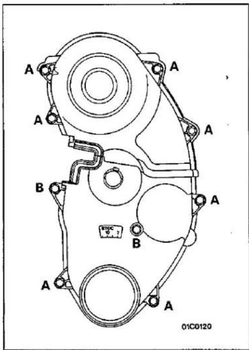
Install the bolts, being careful not to mistake the bolt sizes.
A bolt: 6 × 18 (0.24 × 0.72)
B bolt: 6 × 30 (0.24 × 1.18)
[diameter × length mm (in.)]
5. INSTALLATION OF CRANKSHAFT PULLEY/4. CRANKSHAFT BOLT
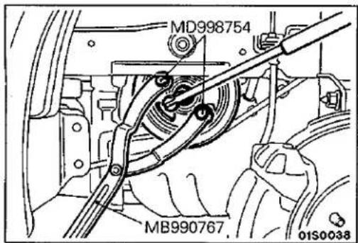
(1) Apply engine oil to the bearing surface and to the thread section of the crankshaft bolt.
(2) Use the special tool to stop the crankshaft pulley from turning, and install the crankshaft bolt.
Caution
Hold the special tool securely so that it doesn't move.
TIMING BELT <4G93>
E11GA-2
REMOVAL AND INSTALLATION
Pre-removal and Post-installation Operation
- Removal and Installation of Under Cover
- Removal and Installation of Crankshaft Pulley (Refer to P.11-42.)
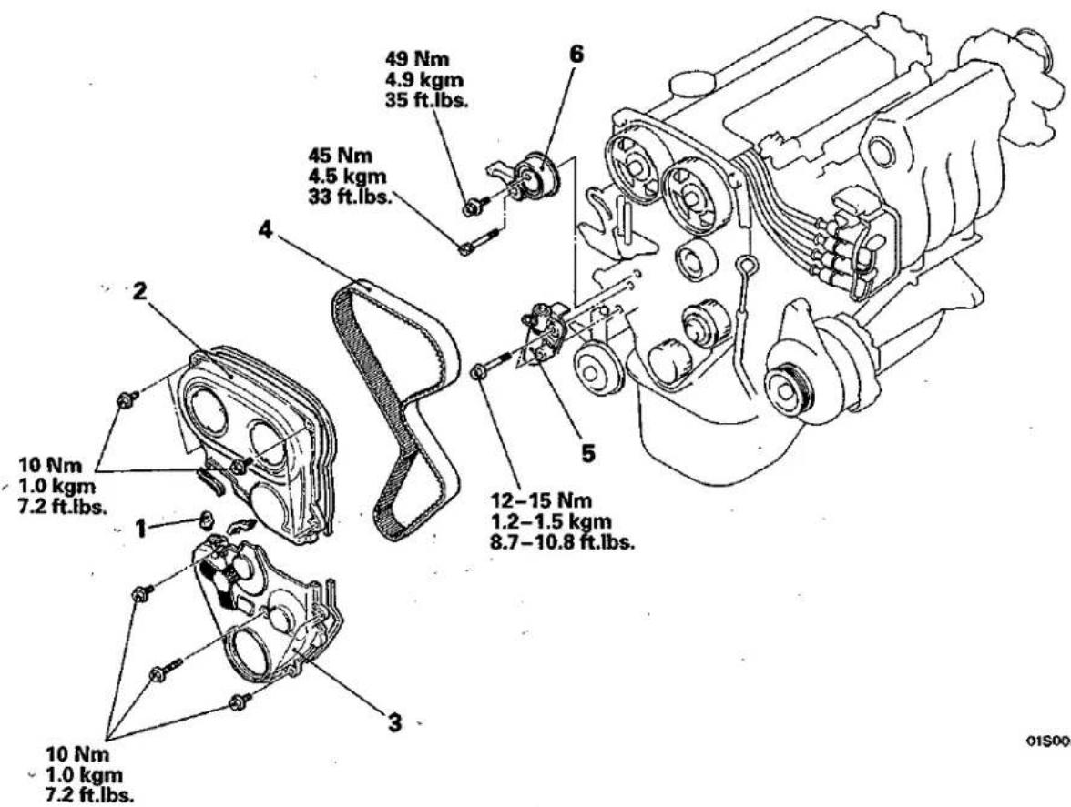
Removal steps
- Rubber plug
- Timing belt upper cover
- Timing belt lower cover
- Adjustment of timing belt tension
- Timing belt
- Auto tensioner
- Tension pulley and arm assembly


SERVICE POINTS OF REMOVAL
E11GBGD
4. REMOVAL OF TIMING BELT
(1) Turn the crankshaft clockwise to align each timing mark.
Caution
The crankshaft must always be turned clockwise.
(2) Loosen the tensioner pulley center bolt and remove the timing belt.
Caution
If the timing belt is to be re-used, use chalk to mark (on its flat side) an arrow indicating the clockwise direction.
SERVICE POINTS OF INSTALLATION
E11GDGE
5. INSTALLATION OF AUTO TENSIONER
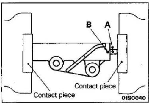
(1) Using a press or vise, compress the push rod of the auto tensioner as slowly as possible and align pin hole A of the push rod and pin hole B of the tensioner cylinder.
Caution
(1) The auto tensioner must be placed at a right angle to the pressing surface of the press or vise.
(2) If the compression speed is too fast, the push rod may become bent, so carry out this operation slowly.
© Mitsubishi Motors Corporation
Jun. 1992
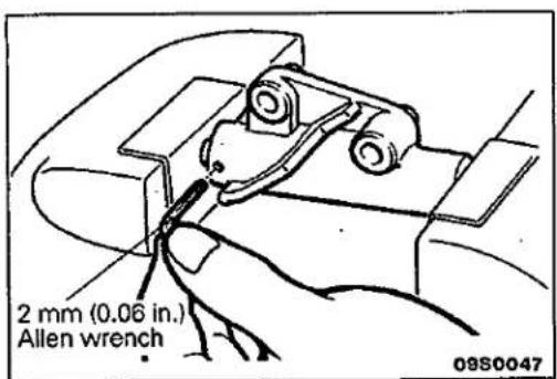
(2) Insert a 2.0 mm (0.06 in.) Allen wrench into the aligned pin holes.
NOTE
If the auto tensioner has been replaced, the pins are set in the auto tensioner.
(3) Install the tensioner to engine.
PWME9117-A
REVISED
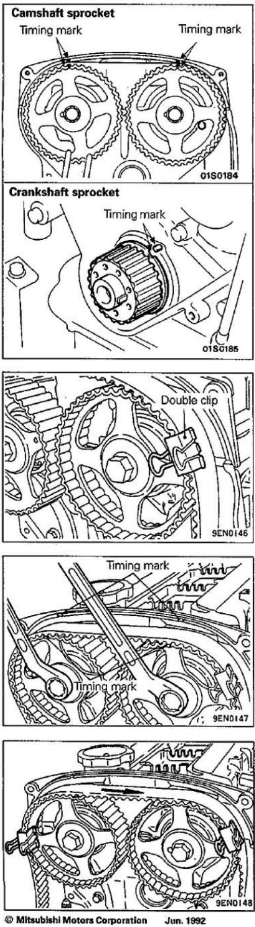
4. INSTALLATION OF TIMING BELT
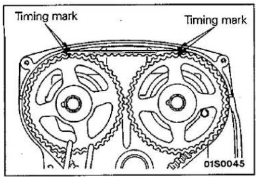
(1) Align the timing marks of each camshaft sprocket and the crankshaft sprocket.
(2) Loosen the tensioner pulley center bolt.
(3) Move the crankshaft sprocket half a tooth width in the anti-clockwise direction.
(4) Place the timing belt on the intake-side camshaft sprocket, and hold it in the position shown in the illustration with a double clip.
(5) Place the timing belt on the exhaust-side sprocket while using two wrenches to align the timing marks.
(6) Hold the belt in the position shown in the illustration with another double clip.
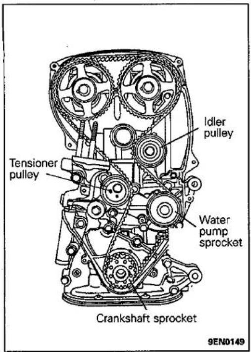
(7) Place the belt onto the idler pulley, water pump sprocket, crankshaft sprocket and tensioner pulley in that order.
(8) Remove the two double clips.
natural_image
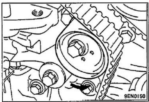
Mechanical gear assembly diagram showing meshing gears and shafts (no text or labels)(9) Lift the tensioner pulley in the direction of the arrow and tighten the tensioner pulley bolt.
(10) Check to be sure that all timing marks are aligned.
(11)Adjust the timing belt tension.
NOTES
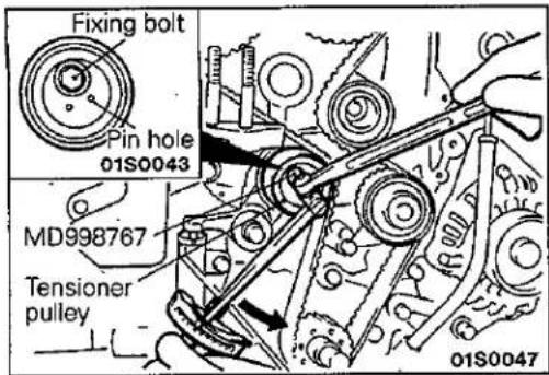
• ADJUSTMENT OF TIMING BELT TENSION
(1) After turning the crankshaft a 1/4 turn anti-clockwise, turn it clockwise to the position where the timing marks are aligned.
(2) Loosen the fixing bolt of the tensioner pulley and using the special tool and a torque wrench, apply tension to the timing belt; then tighten the fixing bolt at the specified torque.
Standard value: 0.26 kgm (timing belt tension torque)
Caution
When tightening the fixing bolt, ensure that the tensioner pulley shaft doesn't rotate with the bolt.
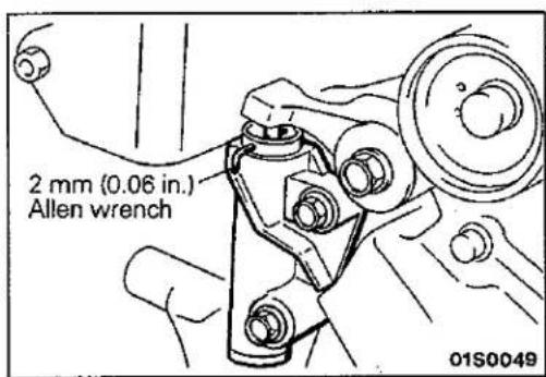
(3) Take out the 2mm (0.06 in) Allen wrench from the auto tensioner. At this time, check to be sure that the 2mm (0.06 in) Allen wrench can be pulled out easily.
Turn the crankshaft clockwise 2 turns, and after leaving it in this position for 5 minutes or more, check again to be sure that the auto tensioner 2mm (0.06 in) Allen wrench can be pulled out or inserted easily.
natural_image
Mechanical assembly diagram showing a lever mechanism with no visible text or symbolsNOTE
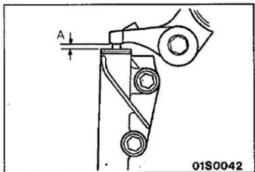
Even if the 2mm (0.06 in) Allen wrench cannot be easily inserted, then it is satisfactory if the amount of protrusion of the auto tensioner rod is within the standard value.
Standard value: 3.8–4.5 mm (0.15–0.17 in)
If it is outside the standard value, repeat the operations in steps (1) to (4).
(4) Check to be sure that the timing marks on all sprockets are aligned
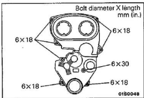
3. INSTALLATION OF TIMING BELT LOWER COVER/2. TIMING BELT UPPER COVER
The dimensions of the installation bolts for the timing belt covers differ according to the installation location, so be sure not to install the bolts in the incorrect locations.
ENGINE ASSEMBLY <4G92>
E11TA-1
REMOVAL AND INSTALLATION
Pre-removal Operation
- Releasing of Fuel Line Pressure (Refer to GROUP 13 – Service Adjustment Procedures.)
• Removal of the Hood - Draining of the Coolant (Refer to GROUP 14 – Service Adjustment Procedures.)
- Removal of the Transmission Assembly (Refer to GROUP 22, 23 – Transmission Assembly.)
- Removal of the Radiator (Refer to GROUP 14 – Radiator.)
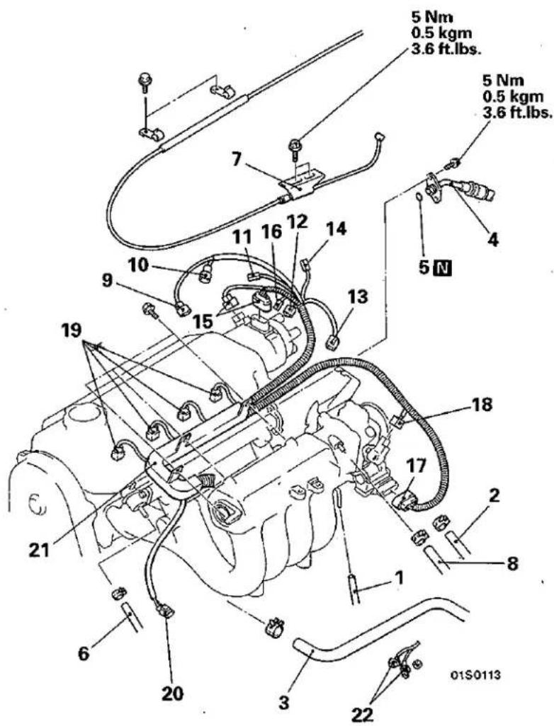
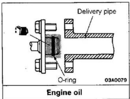
Removal steps
- Vacuum hose connection
- Heater hose connection (Thermostat housing → heater unit)
- Heater hose connection (Heater unit → Water inlet pipe)
- Fuel high pressure hose connection
- O-ring
- Fuel return hose connection
- Accelerator cable connection
-
Brake booster vacuum hose connection
-
Engine coolant temperature switch connector
* 10. Oxygen sensor connector - Oil pressure switch connector
- Water temperature gauge unit connector
13: Engine coolant temperature sensor connector- Engine coolant temperature switch connector (for condenser fan)
- Distributor connector
- Condenser connector
- Idle speed control connector
- TPS connector
- Injector connector
- Detonation sensor connector
- Control harness assembly
- Alternator harness connection
Post-installation Operation
- Installation of the Radiator (Refer to GROUP 14 – Radiator.)
- Installation of the Transmission Assembly (Refer to GROUP 22, 23 – Transmission Assembly.)
- Supplying of the Coolant (Refer to GROUP 14 – Service Adjustment Procedures.)
• Installation of the Hood - Accelerator Cable Adjustment (Refer to GROUP 13 – Service Adjustment Procedures.)
● V-ribbed Belt Tension Adjustment of Power Steering Oil Pump and Air Conditioner Compressor (Refer to P.11-35.)
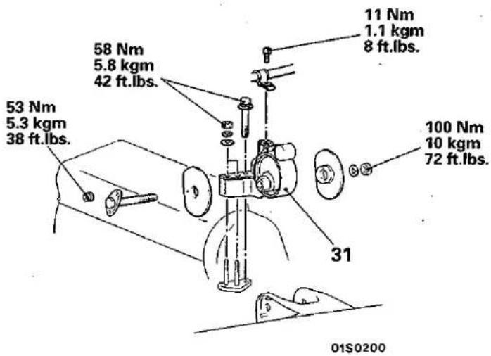
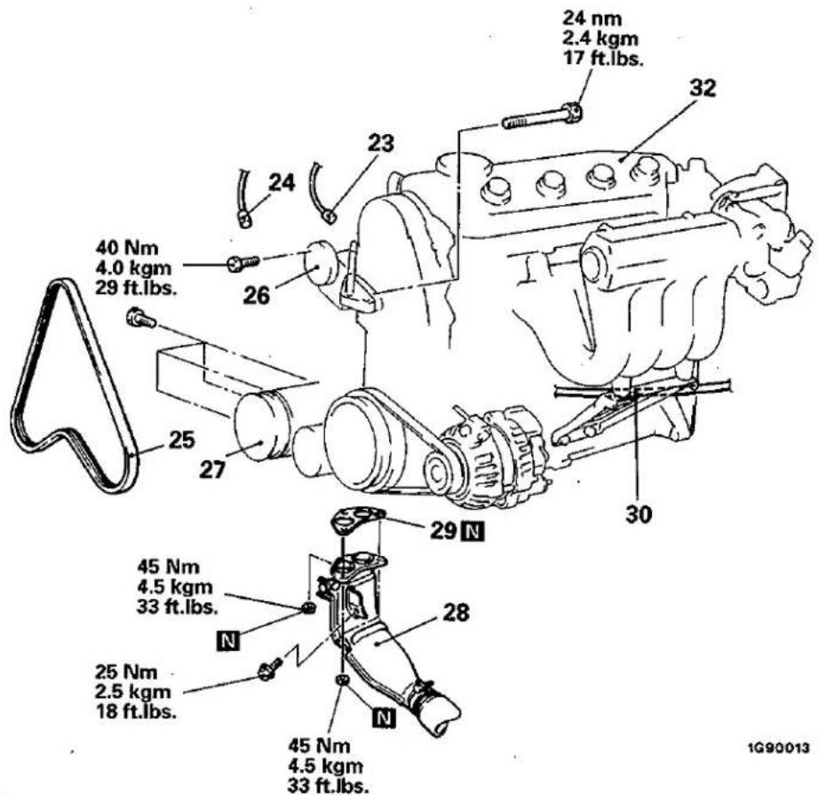
Removal steps


- Power steering oil pressure switch connector
- Air conditioner compressor connector
- V-ribbed belt
- Power steering oil pump connection
- Air conditioner compressor connection
- Front exhaust pipe connection
- Gasket
- Starter and alternator harness clamp
- Engine mount bracket
- Engine assembly
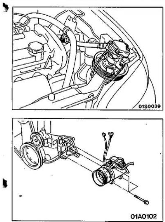
SERVICE POINTS OF REMOVAL
E11TBAN
26. REMOVAL OF POWER STEERING OIL PUMP
Remove the power steering oil pump from the bracket with the hose attached.
NOTE
Place the removed power steering oil pump in a place where it will not be a hindrance when removing and installing the engine assembly, and tie it with a cord.
27. REMOVAL OF AIR CONDITIONER COMPRESSOR
Disconnect the air conditioner compressor connector and remove the compressor from the compressor bracket with the hose still attached.
NOTE
Place the removed air conditioner compressor in a place where it will not be a hindrance when removing and installing the engine assembly, and tie it with a cord.
31. REMOVAL OF ENGINE MOUNT BRACKET
(1) Support the engine with a garage jack.
(2) Hold the engine assembly with a chain block, etc.
(3) Place the garage jack against the engine oil pan with a piece of wood in between, and after raising the engine until there is no weight on the engine mount brackets, remove the engine mount brackets.
32. REMOVAL OF ENGINE ASSEMBLY
After checking that all cables, hoses and harness connectors, etc., are disconnected from the engine; lift the chain block slowly to remove the engine assembly upward from the engine compartment.
SERVICE POINTS OF INSTALLATION
E11TDAQ
32. INSTALLATION OF ENGINE ASSEMBLY
Install the engine assembly while checking to be sure that the cables, hoses, and harness connectors are not clamped.
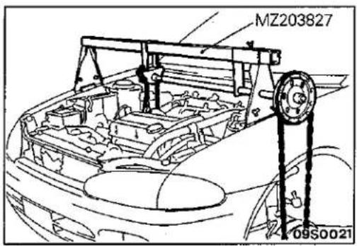
31. INSTALLATION OF ENGINE MOUNT BRACKET
(1) Place a garage jack against the engine oil pan with a piece of wood in between, and install the engine mount bracket while adjusting the position of the engine.
(2) Support the engine with a garage jack.
(3) Remove the chain block and support the engine assembly with the special tool.
ENGINE ASSEMBLY <4G93>
E11TA-2
REMOVAL AND INSTALLATION
Pre-removal Operation
- Releasing of Fuel Line Pressure (Refer to GROUP 13 – Service Adjustment Procedures.)
- Removal of the Hood
- Draining of the Coolant (Refer to GROUP 14 – Service Adjustment Procedures.)
- Removal of the Transmission Assembly (Refer to GROUP 22, 23 – Transmission Assembly.)
- Removal of the Radiator (Refer to GROUP 14 – Radiator.)
Post-installation Operation
- Installation of the Radiator (Refer to GROUP 14 - Radiator.)
- Installation of the Transmission Assembly (Refer to GROUP 22, 23 – Transmission Assembly.)
- Supplying of the Coolant (Refer to GROUP 14 – Service Adjustment Procedures.)
• Installation of the Hood - Accelerator Cable Adjustment (Refer to GROUP 13 – Service Adjustment Procedures.)
- V-ribbed Belt Tension Adjustment of Power Steering Oil Pump and Air Conditioner Compressor (Refer to P.11-35.)
Removal steps
- Accelerator cable connection
- Brake booster vacuum hose connection
- Breather hose connection
- Positive crankcase ventilation hose connection
- High-pressure hose connection
- O-ring
- Return hose connection
- Heater hose connection
- Vapour hose connection
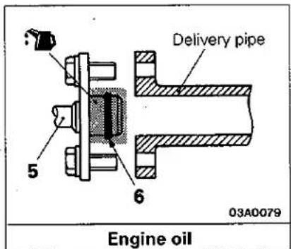
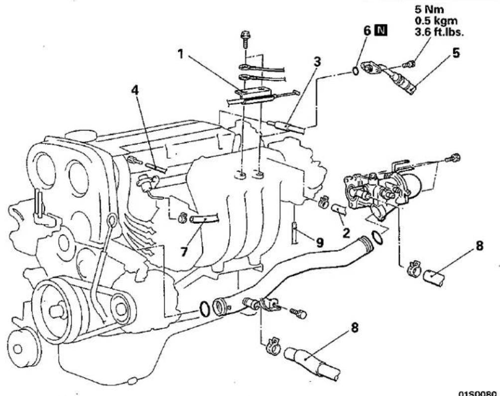
- Engine coolant temperature switch connector (for A/C)
- Oil pressure switch connector
- Oxygen sensor connector
- Engine coolant temperature switch connector
- Water temperature gauge unit connector
- Injector connector
- Crank angle sensor connector
- Throttle position sensor connector
- Idle speed control connector
- Power transistor connector
- Ignition coil connector
- Control harness
- Alternator connector
- Detonation sensor connector
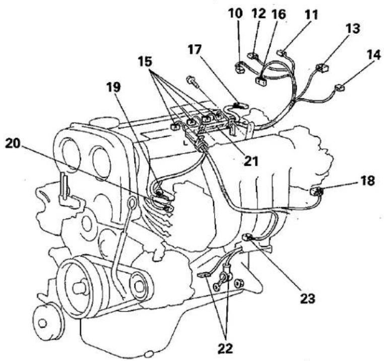
01S0090
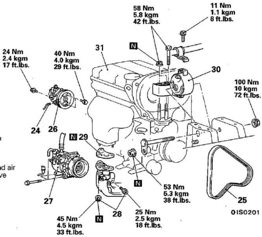
- Power steering oil pressure switch connector
- Adjustment of drive belts (Refer to P.11-8.)
- Power steering oil pump and air conditioner compressor drive belt
- Power steering oil pump (Refer to P.11-75.)
- Air conditioner compressor (Refer to P.11-75.)
- Self-locking nuts and bolts
- Gasket
- Engine mount bracket (Refer to P.11-75, 76.)
- Engine assembly (Refer to P.11-75, 76.)
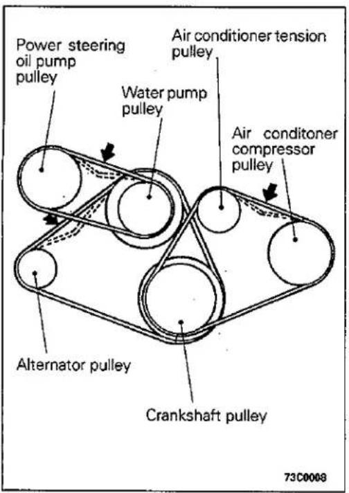
ENGINE <4D68>
SERVICE ADJUSTMENT PROCEDURES
DRIVE BELT TENSION INSPECTION AND ADJUSTMENT E11F0BQ
DRIVE BELT TENSION INSPECTION
Check the tension by pulling or pushing at the centre of the belt between pulleys with a force of 98 N (10 kg, 22 lbs.) as shown in the figure.
Measure drive belt deflection amount.
Standard value:
mm (in.)
| Items | During inspection | When retightening used belt | When fitting new belt |
| Alternator drive belt | 7.0 – 10.0(0.28 – 0.39) | 8.0 – 9.0(0.31 – 0.35) | 6.0 – 7.0(0.24 – 0.28) |
| Power steering oil pump drive belt | 5.5 – 8.0(0.22 – 0.31) | 6.0 – 7.0(0.24 – 0.28) | 4.5 – 5.5(0.18 – 0.22) |
| Air conditioner compressor drive belt | 7.0 – 8.0(0.28 – 0.31) | 7.0 – 8.0(0.28 – 0.31) | 5.0 – 6.0(0.20 – 0.24) |
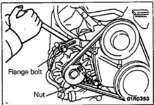
DRIVE BELT TENSION ADJUSMENT
ALTERNATOR DRIVE BELT
(1) Loosen the flange bolt and nut that are securing the alternator.
(2) Apply a bar to the stator section of the alternator and lever it to adjust the belt deflection amount so that it is at the standard value.
(3) Tighten the flange bolt and nut that were previously loosened to the specified torque.
Tightening torque
| Flange bolt: | 12 – 15 Nm |
| 1.2 – 1.5 kgm | |
| 10 – 11 ft.lbs. | |
| Nut: | 20 – 25 Nm |
| 2.0 – 2.5 kgm | |
| 14 – 18 ft.lbs. |
(4) Turn the crankshaft one full rotation or more in the forward direction (rotation to the right) to turn over the engine, and then recheck the belt deflection amount and readjust if necessary.
NOTE
The crankshaft should always be turned in the forward direction of rotation.
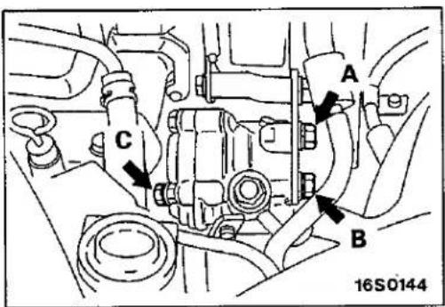
POWER STEERING OIL PUMP DRIVE BELT
(1) Loosen power steering oil pump fixing bolt.
(2) Move power steering oil pump, tension belt moderately and adjust tension.
(3) Tighten the fixing bolts in the order A, B and C.
Tightening torque: 39 Nm (4.0 kgm, 29 ft.lbs.)
(4) Check belt tension after driving.
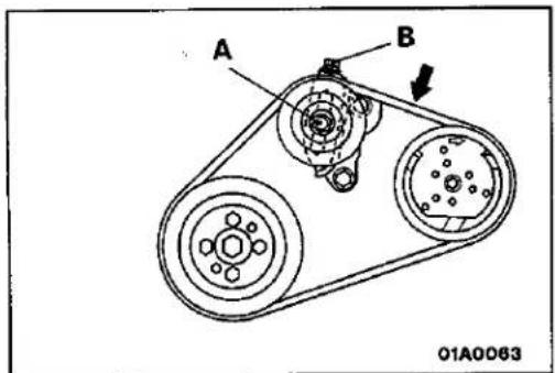
AIR CONDITIONER COMPRESSOR DRIVE BELT TENSION ADJUSTMENT
(1) Loosen tension pulley fixing bolt A.
(2) Adjust belt tension with adjusting bolt B.
(3) Tighten fixing bolt A.
(4) Check the belt tension after driving.
VALVE CLEARANCE INSPECTION AND ADJUSTMENT E11FDAX
(1) Start the engine and allow it to warm up until the engine coolant temperature reaches 80 to 95°C (176 to 203°F).
(2) Remove all glow plugs from the cylinder heads for easy inspection. (Refer to GROUP 16 – Glow System.)
(3) Remove the rocker cover.
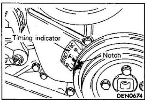
(4) Turn the crankshaft clockwise until the notch on the pulley is lined up with the "T" mark on the timing indicator.
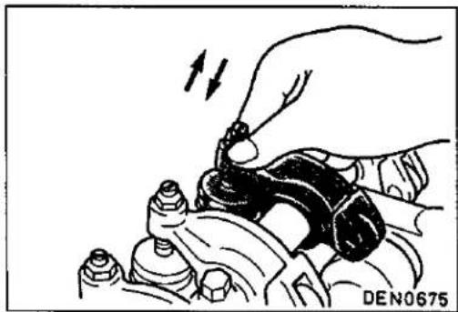
natural_image
Illustration of a hand adjusting a mechanical component with arrows indicating motion (no text or symbols)(5) Move the rocker arms on the No. 1 and No. 4 cylinders up and down by hand to determine which cylinder has its piston at the top dead centre on the compression stroke. If both intake and exhaust valve rocker arms have a valve lash, the piston in the cylinder corresponding to these rocker arms is at the top dead centre on the compression stroke.
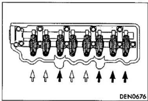
natural_image
Pure electrical circuit lines without any symbols(6) Valve clearance inspection and adjustment can be performed on rocker arms indicated by white arrows when the No. 1 cylinder piston is at the top dead centre on the compression stroke, and on rocker arms indicated by solid arrows when the No. 4 cylinder piston is at the top dead centre on the compression stroke.
(7) Measure the valve clearance.
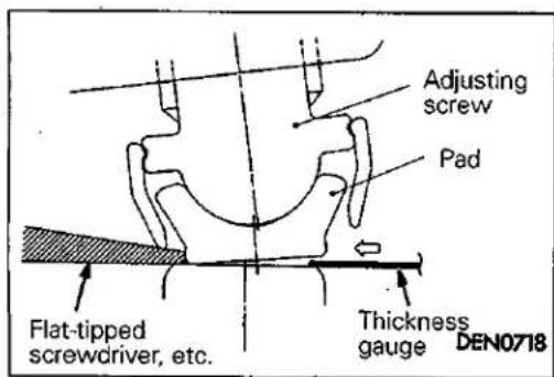
NOTE
When inserting the thickness gauge, push the pad from the opposite side from the thickness gauge insertion side with a flat-tipped screwdriver or similar tool to make a gap, and then insert the thickness gauge.
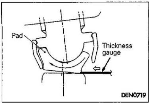
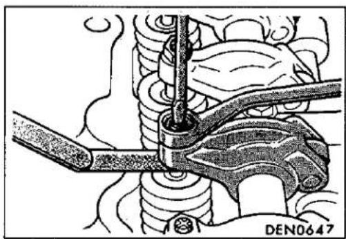
natural_image
Mechanical assembly diagram showing a hand operating a valve with a coiled spring (no text or symbols visible)When you try to insert the thickness gauge, if the pad is not pushed with a flat-tipped screwdriver or similar tool and no gap is made, the pad will tilt as shown in the illustration and the thickness gauge will not be able to be inserted.
(8) If the valve clearance is not as specified, loosen the rocker arm lock nut and adjust the clearance using a thickness gauge while turning the adjusting screw.
Standard value (hot engine):
Intake valve
0.25 mm (0.010 in.)
Exhaust valve
0.25 mm (0.010 in.)
(9) While holding the adjusting screw with a screwdriver to prevent it from turning, tighten the lock nut securely.
(10) Turn the crankshaft through 360° to line up the notch on the crankshaft pulley with the "T" mark on the timing indicator.
(11) Repeat steps (6) and (7) on other valves for clearance adjustment.
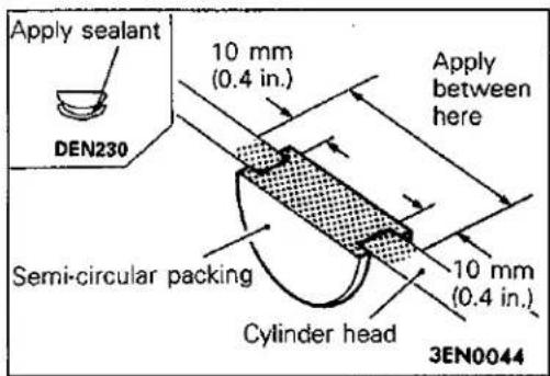
(12) Apply a coating of the specified sealant to the semi-circular packing and cylinder head to surfaces.
Specified sealant: 3M ATD Part No. 8660 or equivalent
(13) Install the rocker cover.
(14) Install the glow plugs and tighten to the specified torque.
Tightening torque: 18 Nm (1.8 kgm, 13 ft.lbs.)
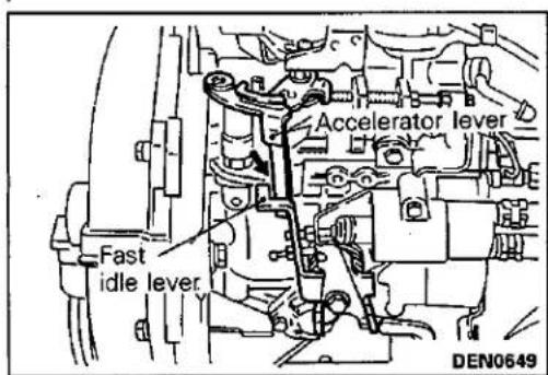
INJECTION TIMING ADJUSTMENT
E11FVAK
(1) After warming up the engine, check to be sure that the fast idle lever is separated from the accelerator lever.
(2) To make the crankshaft turn more easily, remove the four glow plugs.
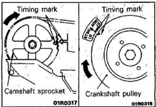
(3) Turn the crankshaft clockwise (right turn) to align each timing mark and to set the NO. 1 cylinder at compression top dead centre.
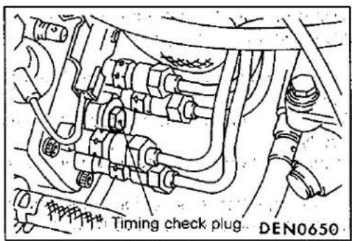
(4) Remove the timing check plug installed at the rear of the injection pump.
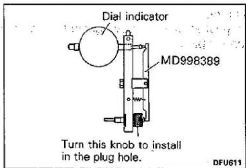
(5) Install the special tool to the rear of the injection pump.
(6). Install a dial gauge to the special tool.
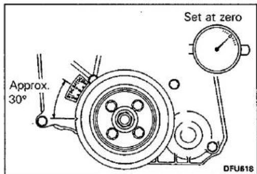
(7) Turn the crankshaft clockwise to move the No. 1 cylinder approximately 30° before compression top dead centre..
(8) Set the needle of the dial gauge to 0.
(9) Check to be sure that the needle doesn't move even if the crankshaft is turned slightly (2–3°) both clockwise and anticounter clockwise.
(10) If the needle moves, the injection pump pluger is lifted, so reset it by turning the crankshaft to a position where the needle doesn't move.
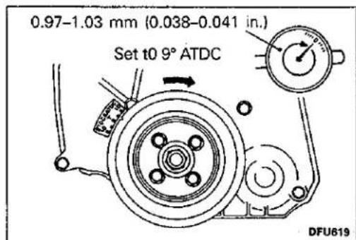
(11)Turn the crankshaft pulley clockwise to align the crankshaft pulley notch to 9° ATDC.
(12) Take a reading of the value displayed on the dial gauge.
Standard value: 0.97–1.03 mm (0.038–0.041 in.)
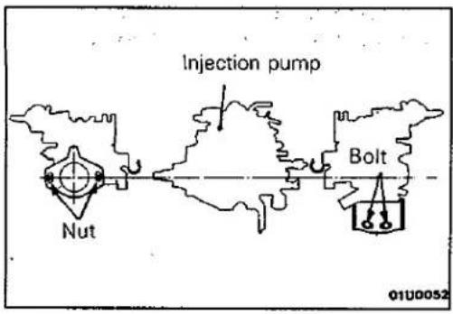
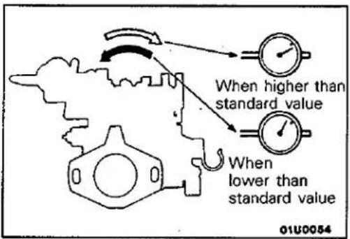
(13) If the value is outside the standard value, adjust the injection timing by the following procedure.
① Loosen the four injection pipe union nuts on the injection pump side. (Do not remove the union nuts.) When loosening the nuts, hold the delivery valve holders with a spanner so that they don't turn a the same time.
② Loosen the two injection pump mounting nuts and the two injection pump mounting bolts. (Do not remove the nuts and bolts.)
③ Tilt the injection pump to the left and right and adjust so that the value displayed on the dial gauge is at the standard value.
④ Temporarily tighten the two mounting nuts and bolts of the injection pump.
⑤ Repeat steps (7) – (12) to check if the adjustment has been made correctly.
⑥ Securely tighten the injection pump mounting nuts and bolts.
⑦ Securely tighten the injection pipe union nuts. When tightening the nuts, hold the delivery valve holders with a spanner so that they don't turn at the same time.
(14) Remove the special tool.
(15) After replacing the gasket with a new gasket, securely tighten the timing check plug.
ENGINE IDLE SPEED INSPECTION AND ADJUSTMENT
NOTE
Carry out inspection and adjustment of the idle speed after checking that the injection timing is normal.
(1) Before inspection and adjustment set vehicle in the following condition.
• Engine coolant temperature: 80–95°C (176–203°F)
- Lamps, electric cooling fan and all accessories: OFF
• Transmission: Neutral
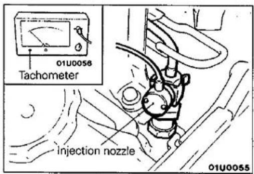
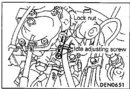
(2) Connect a tachometer to the injection nozzle or the injection pipe.
Caution
When the tachometer is connected to the injection pipe, the pipe mounting clamps should all be removed.
(3) Check the idle speed.
Standard value: 750 ± 100 r/min.
(4) If the idle speed is outside the standard value, loosen the lock nut on the idle adjusting screw and adjust by turning the idle adjusting screw..
After adjustment, securely tighten the lock nut.
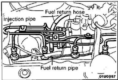
COMPRESSION PRESSURE INSPECTION
E11FGAP
(1) Check to be sure that the engine oil, starting motor and battery are in the normal condition.
(2) Start the engine and allow it to warm up until the temperature of the engine coolant reaches 80 to 95°C (176 to 203°F).
(3) Remove the injection pipes.
(4) Remove the fuel return hose.
(5) Hold the hexagonal section of the fuel return pipe with a wrench, and remove the nut that fastens the pipe to each injection nozzle.
(6) Remove the fuel return pipe and gasket.
(7) Using a deep socket wrench, remove all the injection nozzles.
NOTE
Attach a tag indicating the cylinder number to each nozzle that has been removed.
(8) Remove the holder gasket and nozzle gasket from the injection nozzle hole in the cylinder head.
(9) Disconnect the fuel cut solenoid valve connector.
NOTE
This will stop fuel injection from being carried out.
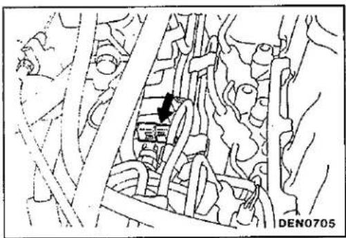
natural_image
Technical line drawing of a mechanical assembly with no visible text or symbols(10) Cover the injection nozzle mounting hole with a rag, and after the engine has been cranked, check that no foreign material is adhering to the rag.
Caution
- Keep away from the injection nozzle mounting hole when cranking.
- If compression is measure while water, oil, fuel, etc., that has come from cracks is inside the cylinder, these materials will become heated and will gush out from the injection nozzle mounting hole, which is dangerous.
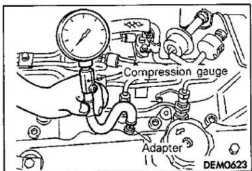
(11) Attach the adapter to the injection nozzle hole and connect a compression gauge to the adapter.
(12) Crank the engine and measure the compression pressure.
Standard value (at engine speed of 250 r/min.):
3,500 kPa (35.0 kg/cm, 498 psi)
Limit (at engine speed of 250 r/min.):
min. 2,560 kPa (25.6 kg/cm, 364 psi)
(13) Measure the compression of all the cylinders, and check that the pressure differences between each cylinder are below the limit.
Limit: max. 300 kPa (3.0 kg/cm, 43 psi)
(14) If there is a cylinder with compression or a compression difference that is outside the limit, pour a small amount of engine oil through the injection nozzle mounting hole, and repeat the operations in steps (11) to (13).
① If the compression increases after oil is added, the cause of the malfunction is a worn or damaged piston ring and/or cylinder inner surface.
② If the compression does not rise after oil is added, the cause is a burnt or defective valve seat, or pressure is leaking from the gasket.
(15)Connect the fuel cut solenoid valve connector. For information regarding the servicing procedures for these causes of malfunction, refer to the ENGINE AND TRANSMISSION MANUAL.
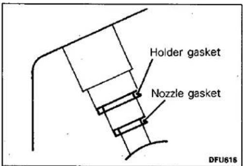
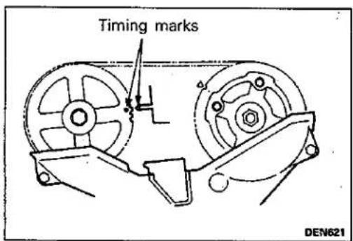
(16) Clean nozzle holder installation area of the cylinder head. (17) Fit a new nozzle gasket and holder gasket into the nozzle holder hole in the cylinder head. (18) Install the injection nozzles in their correct position referring to the cylinder numbers indicated on the tags that were attached to each nozzle at the time of removal. Tighten the nozzles to specified torque.
Tightening torque: 55 Nm (5.5 kgm, 40 ft.lbs.)
(19) Install the gaskets and fuel return pipe. (20) Install the injection pipes.
TIMING BELT ADJUSTMENT
E11FFDI
(1) Turn crankshaft clockwise to bring No. 1 cylinder piston to top dead centre on compression stroke.
Caution For aligning the timing marks, never turn the crankshaft anticlockwise as it could cause inadequate belt tension.
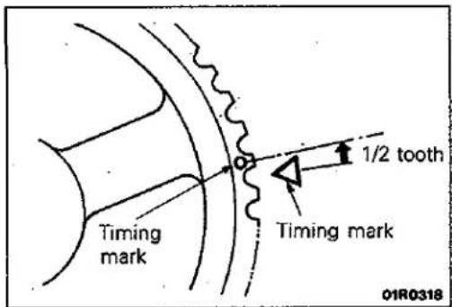
(2) Turn the crankshaft anticlockwise by a distance equivalent to 1/2 tooth of the camshaft sprocket in order to correct looseness of the belt at the idler side.
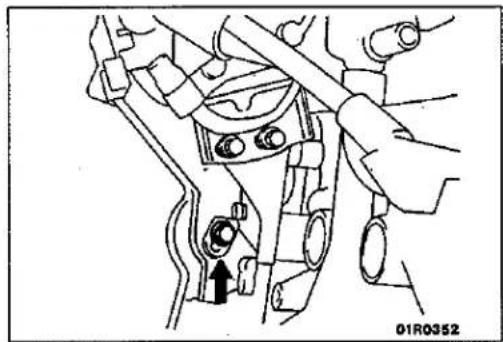
natural_image
Mechanical assembly diagram showing a lever mechanism with no visible text or symbols(3) Using a long extension, loosen the installation bolt of the timing belt tension (from the engine rear) by 1/6 to 1/2 turn, taking advantage of the force of the tensioner spring to provide tension to the belt.
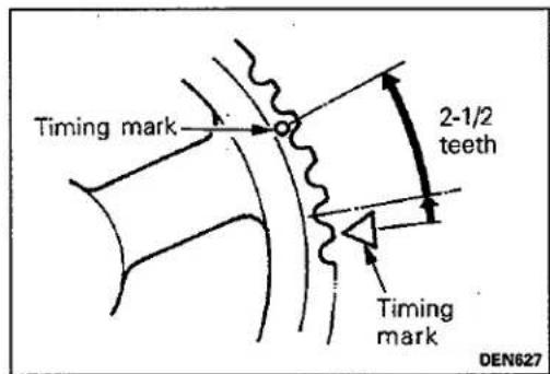
(4) In addition, turn the crankshaft anticlockwise by a distance equivalent to 2-1/2 teeth.
NOTE
When the setting is as described above, the camshaft will be slightly past compression top dead centre of the No. 1 cylinder, and the looseness of the timing belt will be at the tension side.
Caution
Do not rotate the crankshaft clockwise, because the tensioner side will become stretched and the adjustment will be unsuitable.
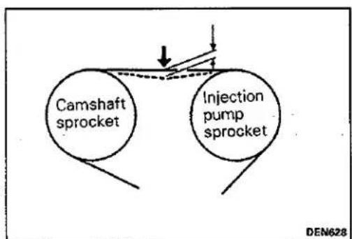
flowchart
graph TD
    A["Camshaft sprocket"] --> B["Injection pump sprocket"]
    style A fill:#fff,stroke:#000
    style B fill:#fff,stroke:#000
    style A -.-> C["Arrow down"]
    style B -.-> D["Arrow up"]
(5) Tighten the timing belt tensioner at the specified torque.
(6) Turn the crankshaft clockwise and align the timing mark.
(7) Using the index finger, press between the camshaft sprocket and the injection pump and sprocket, and check whether or not the amount of flexion is within the standard value range or not.
Standard value range: 4.0–5.0 mm (0.16–0.20 in.)
If there is a deviation from the standard value range, repeat steps (2) to (5).
CRANKSHAFT PULLEY
REMOVAL AND INSTALLATION
Pre-removal and Installation Operation
- Removal and Installation of Under Cover
E11LA-
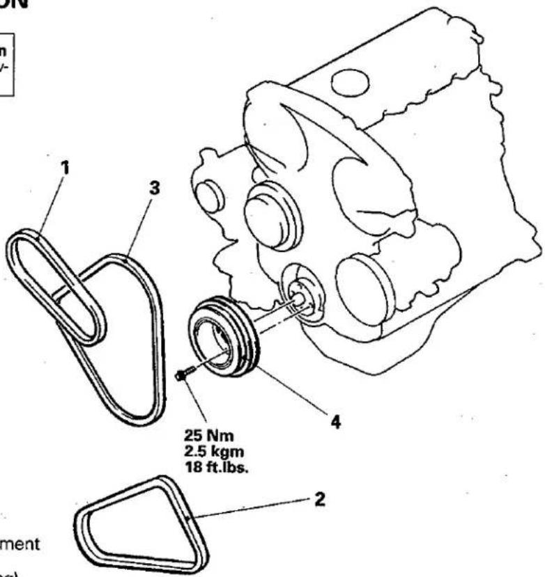
Removal steps
- Drive belt tension adjustment (Refer to P.11-79)
- Drive belt (Power steering)
- Drive belt (Air conditioner)
- Drive belt (Alternator)
- Crankshaft pulley
01X0020
CAMSHAFT AND CAMSHAFT OIL SEAL
REMOVAL AND INSTALLATION
E11HA--
Pre-removal and Post-installation Operation
- Removal and Installation of Timing Belt (Refer to P.11–103.)
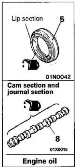
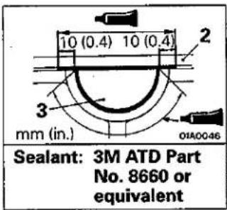
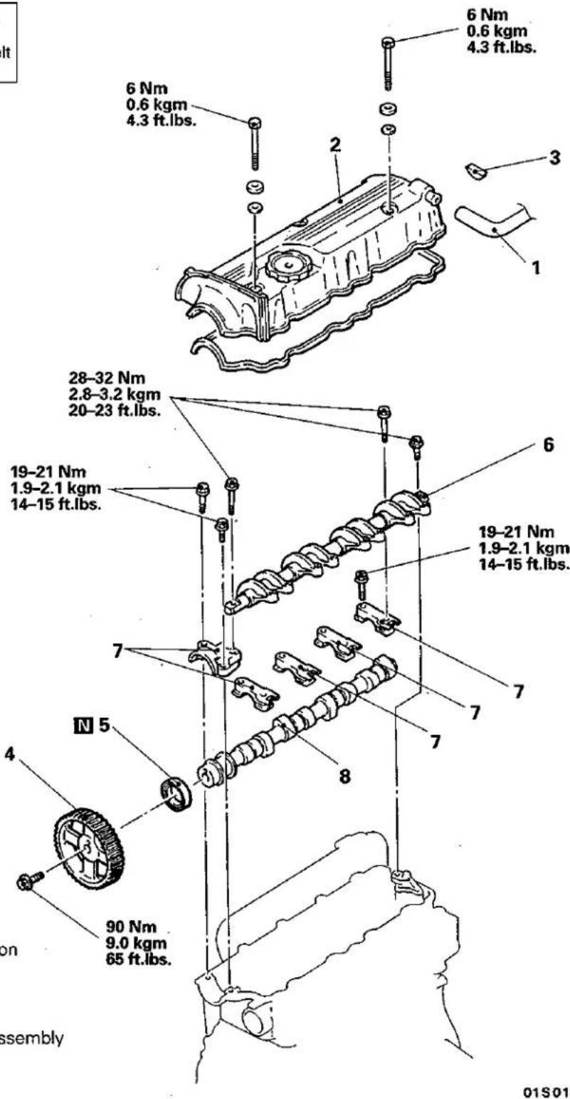
Removal steps
- Breather hose connection
- Rocker cover
- Semi-circular packing
- Camshaft sprocket
- Camshaft oil seal
- Rocker arm and shaft assembly
- Camshaft bearing cap
- Camshaft

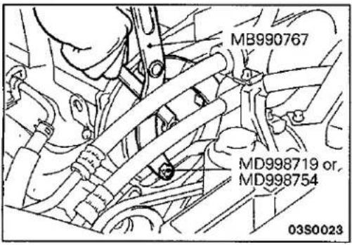
SERVICE POINTS OF REMOVAL
E11HBAO
4. REMOVAL OF CAMSHAFT SPROCKET
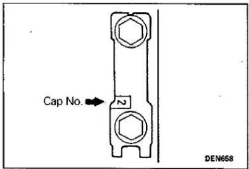
SERVICE POINTS OF INSTALLATION
E11HCAO
7. INSTALLATION OF CAMSHAFT BEARING CAP
The cap numbers are embossed on the top surface of the bearing caps, so install in the order of the numbers. However, no numbers are embossed on bearing caps 1 and 5.
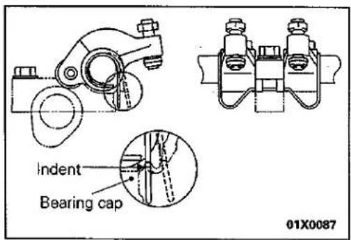
6. INSTALLATION OF ROCKER ARM AND SHAFT ASSEMBLY
(1) Install the rocker arm and shaft assembly to the bearing caps.
(2) Set the rocker arm springs into the bearing cap indents.
(3) Check the valve clearance and adjust if necessary. (Refer to P.11-81.)
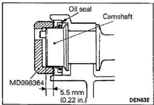
5. INSTALLATION OF CAMSHAFT OIL SEAL
(1) Apply a small amount of engine oil to the entire circumference of the oil seal lip and camshaft.
(2) Use the special tool to tap in the oil seal.
NOTE
The oil seal should be tapped in until the distance from the end of the camshaft to the end of the oil seal is as shown in the illustration.
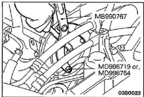
4. INSTALLATION OF CAMSHAFT SPROCKET
OIL PAN
E11KA--
REMOVAL AND INSTALLATION
Pre-removal and Post-installation Operation
• Draining and Supplying of Engine Oil
- Removal and Installation of Oil Level Gauge
- Removal and Installation of Front Exhaust Pipe (Refer to GROUP 15--Exhaust Pipe and Muffler.)
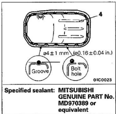

Removal steps
- Bell housing cover
- Drive shaft center bearing mounting bolt
- Oil return hose
- Oil pan
- Drain plug
- Gasket


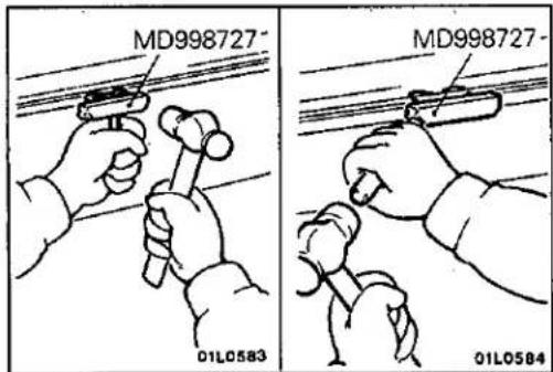
© Mitsubishi Motors Corporation
Jun. 1992
SERVICE POINTS OF REMOVAL
4. REMOVAL OF OIL PAN
E11KBBP
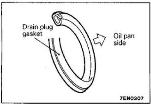
SERVICE POINTS OF INSTALLATION
E11KDBN
6. INSTALLATION OF GASKET
Replace the gasket with a new gasket, and install it in the direction shown in the illustration.
CRANKSHAFT FRONT OIL SEAL
REMOVAL AND INSTALLATION
E11UA-1
Pre-removal and Post-installation Operation
- Removal and Installation of Timing Belt (Refer to P.11-103.)
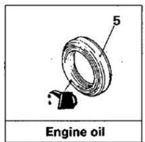


Removal steps
- Crankshaft bolt
- Crankshaft sprocket
- Flange
- Crankshaft sprocket B
- Key
- Crankshaft bolt
110–130 Nm 11–13 kgm 80–94 ft.lbs.
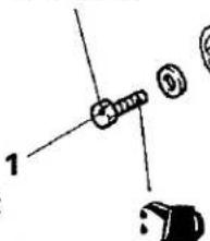
(Engine oil)
N6
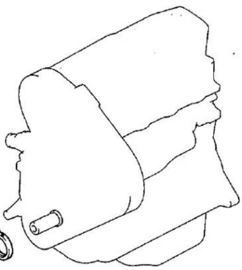
natural_image
Line drawing of a mechanical component with no visible text or symbols01\$0177
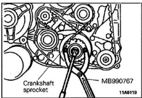
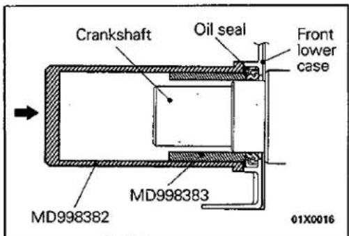
SERVICE POINTS OF REMOVAL
E11UBAI
- REMOVAL OF CRANKSHAFT BOLT/2. CRANKSHAFT SPROCKET
SERVICE POINTS OF INSTALLATION
E11UCAO
6. INSTALLATION OF CRANKSHAFT FRONT OIL SEAL
Apply engine oil to the entire circumference of the oil seal lip, and then tap in the oil seal until it is flush with the front lower case.
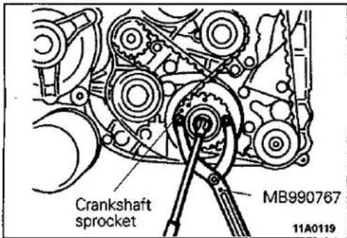
- INSTALLATION OF CRANKSHAFT SPROCKET/1. CRANKSHAFT BOLT
CRANKSHAFT REAR OIL SEAL
REMOVAL AND INSTALLATION
E11UA-2
Pre-removal and Post-installation Operations
- Removal and Installation of Transmission Assembly (Refer to GROUPS 22 and 23 – Transmission Assembly)
- Removal and Installation of Clutch Cover and Disk
- Removal and Installation of Oil Pan (Refer to P.11-92.)
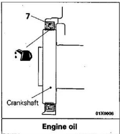
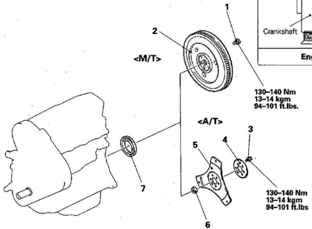
01X0017
Removal steps
- Flywheel bolt }
- Drive plate bolt
- Adapter plate
- Drive plate
- Crankshaft bushing }
- Crankshaft rear oil seal
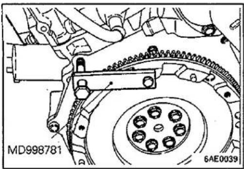
SERVICE POINTS OF REMOVAL
E11UBAJ
1. REMOVAL OF FLYWHEEL BOLT /3. DRIVE PLATE BOLT
Use the special tool to secure the flywheel or drive plate, and remove the bolt.
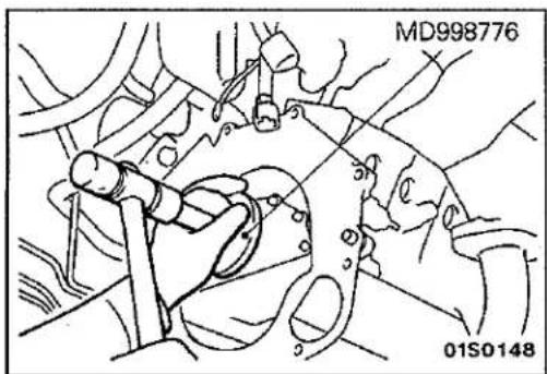
SERVICE POINTS OF INSTALLATION
E11UCAP
7. INSTALLATION OF CRANKSHAFT REAR OIL SEAL
(1) Apply a small amount of engine oil to the entire circumference of the oil seal lip.
(2) Tap in the oil seal as shown in the illustration.
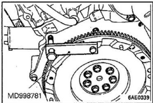
natural_image
Mechanical assembly diagram showing gear and chain components (no text or symbols)3. INSTALLATION OF DRIVE PLATE BOLT /1. FLYWHEEL BOLT
Use the special tool to secure the flywheel or drive plate, and install the bolt.
CYLINDER HEAD GASKET
E11JA--
REMOVAL AND INSTALLATION
Pre-removal and Post-installation Operations
- Draining and Supplying of the Coolant (Refer to GROUP 14 – Service Adjustment Procedures.)
- Draining and Supplying of the Engine Oil
- Removal and Installation of the Air Intake Hose and Air Cleaner Assembly.
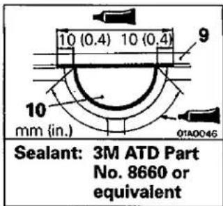
![[Bead diameter 2.3-3.0 mm (0.09-0.12 in.)] 04X0011](/content/2026/05/858112/images/0c22fc6f06d9f872d06fd4e0be3a38d91ddc86a9f94c85ac39ea2726be152e5f.jpg)
Specified sealant: MITSUBISHI GENUINE PART MD970389 or equivalent
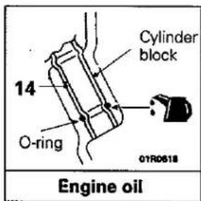
Removal steps
- Engine coolant temperature sensor and engine coolant temperature gauge unit
- Engine coolant temperature switch connector (A/C)
- Glow plug connector
- Engine hanger
- Radiator upper hose connection
- Heater hose connection
- Water hose connection
- Timing belt upper cover
- Rocker cover
- Semi-circular packing
- Glow plug plate
- Glow plug
- Thermostat case assembly
- Oil level gauge
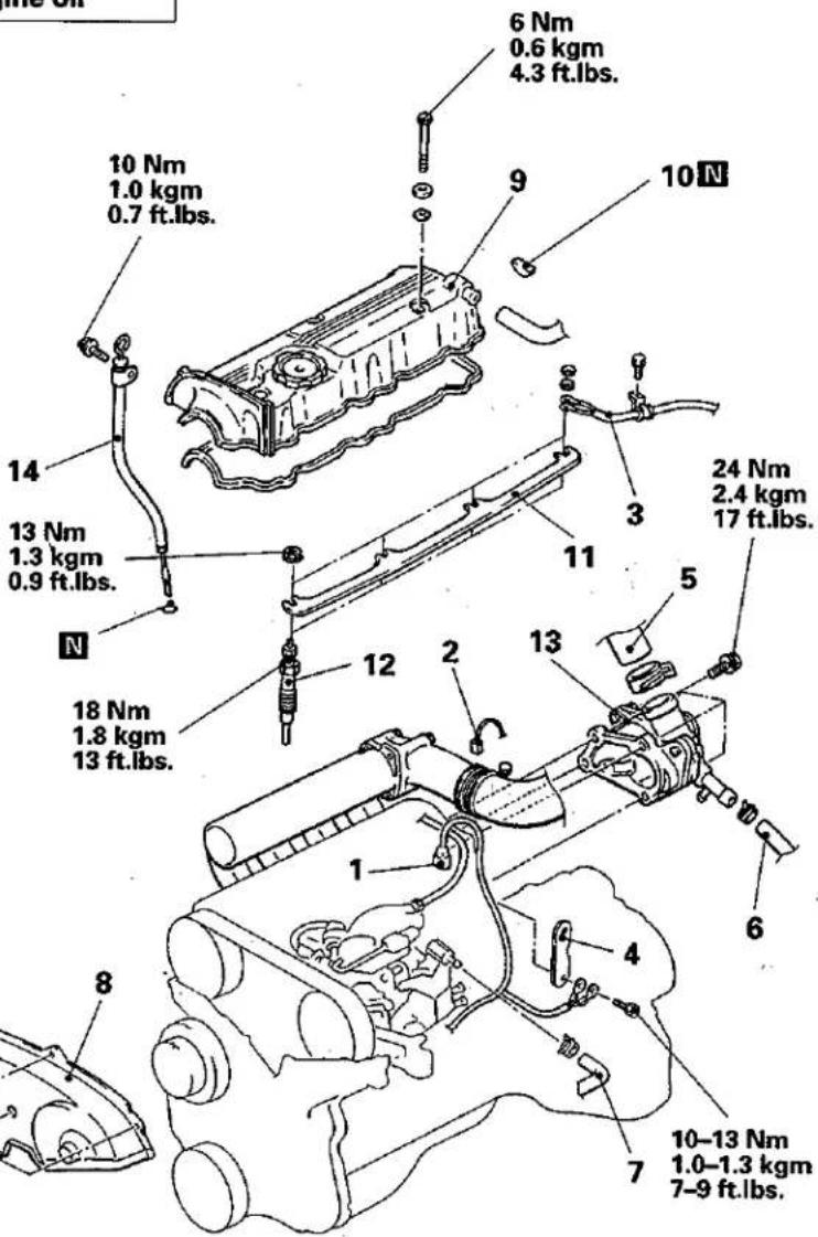
01\$0178
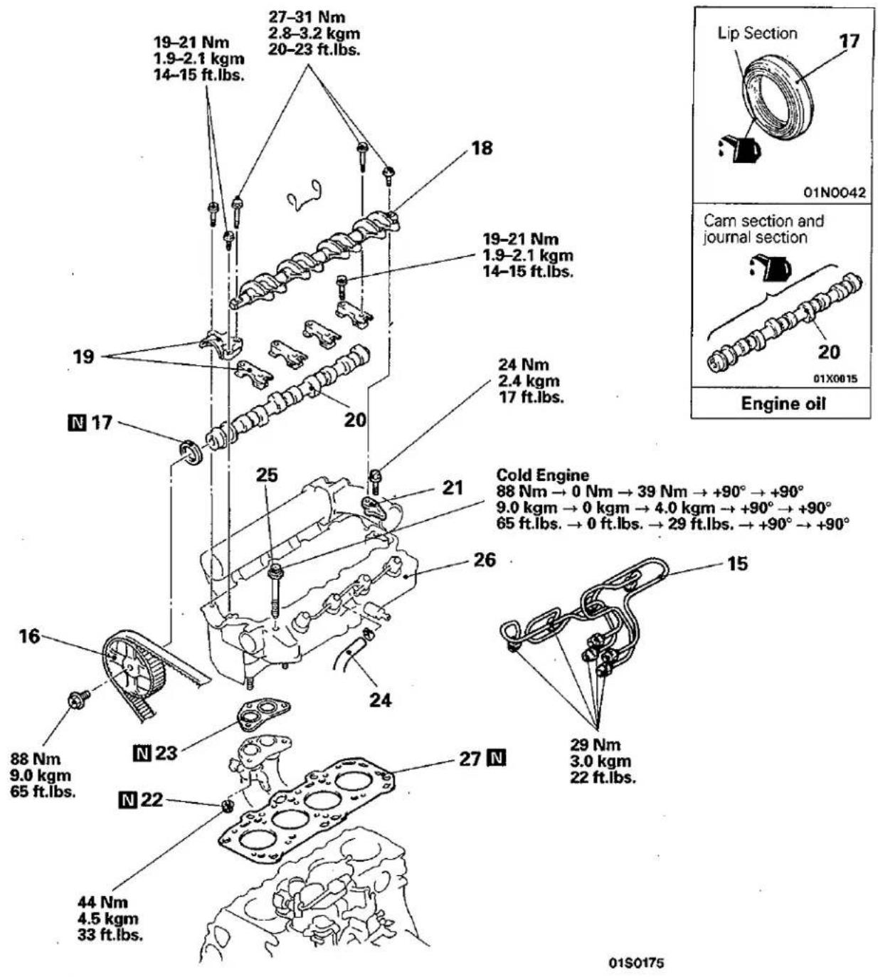
Removal steps
- Fuel injection pipe
- Camshaft sprocket
- Oil seal
- Rocker arm and shaft assembly
- Camshaft bearing cap
- Camshaft
- Rocker shaft support
- Self-locking nut
- Gasket
- Fuel return hose
◆◆ ◆◆ 25. Cylinder head bolt
26. Cylinder head assembly
27. Cylinder head gasket
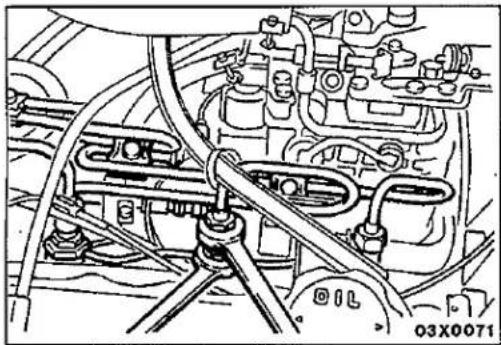
natural_image
Technical line drawing of an engine assembly with hoses and components (no readable text or symbols)SERVICE POINTS OF REMOVAL
E11JBBH
15. DISCONNECTION OF INJECTION PIPE
When loosening nuts at both ends of injection pipe, hold the other side (pump side-delivery holder, nozzle side-nozzle holder) with wrench and loosen nut.
Caution
After disconnecting the injection pipe, plug the opening so that no foreign particles get inside the pump or into the injection nozzle.
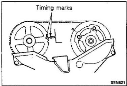
16. REMOVAL OF CAMSHAFT SPROCKET
(1) Rotate the crankshaft clockwise and check that the camshaft sprocket's timing mark and the injection sprocket's timing mark are aligned.
Caution
The crankshaft should always be turned in a clockwise direction.
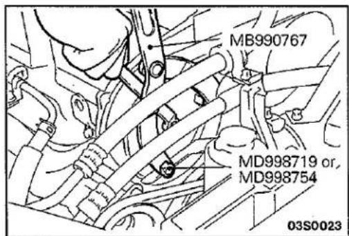
(2) Use the special tool to loosen the camshaft sprocket bolt.
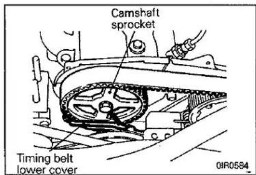
(3) Remove the camshaft sprocket with the timing belt still attached, and place it on the timing belt lower cover.
NOTE
At this time, tie the timing belt and camshaft sprocket and also the timing belt and injection pump sprocket together with cord or similar so that they do not become unmeshed.
Caution
The crankshaft should not be turned after the camshaft sprocket has been removed.
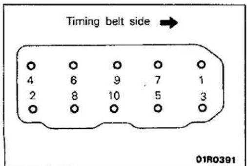
25. REMOVAL OF CYLINDER HEAD BOLT
Loosen each of the bolts in 2 or 3 steps (in the order shown in the illustration), and then remove the cylinder head assembly.
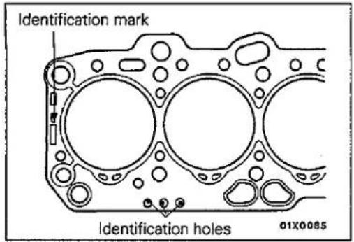
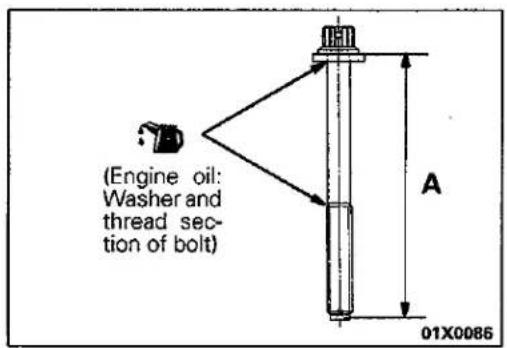
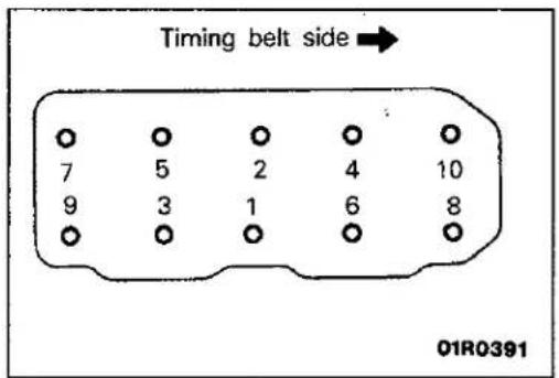
SERVICE POINTS OF INSTALLATION
E11JDCV
27. INSTALLATION OF CYLINDER HEAD GASKET
(1) Wipe off any oil or grease from the gasket mounting surface.
(2) Check the number of identification holes on the cylinder head gasket that was removed, and select a cylinder head gasket with the same number of identification holes.
(3) Place the cylinder head gasket on top of the cylinder block so that the identification mark is facing upwards as in the illustration.
25. INSTALLATION OF CYLINDER HEAD BOLT
(1) When installing the cylinder head bolts, the length below the head of the bolts should be within the standard value. If it is outside the standard value, replace the bolts.
Limit: Within 119.7 mm (4.713 in.)
(2) Apply a small amount of engine oil to the thread section and the washer of the cylinder head bolt.
(3) Tighten the bolts in order by the following procedure.
| Procedure | Operation contents | Remarks |
| 1↓2↓3↓4↓5 | Tighten to 90 Nm(9.0 kgm, 65 ft.lbs.) | Carry out in the order shown in the illustration |
| Fully loosen. | Carry out in the reverse or-der to that shown in the il-lustration | |
| Tighten to 40 Nm(4.0 kgm, 29 ft.lbs.) | Carry out in the order shown in the illustration | |
| Tighten by 1/4 turn(90°) | Carry out in the order shown in the illustration | |
| Tighten by 1/4 turn(90°) | Carry out in the order shown in the illustration |
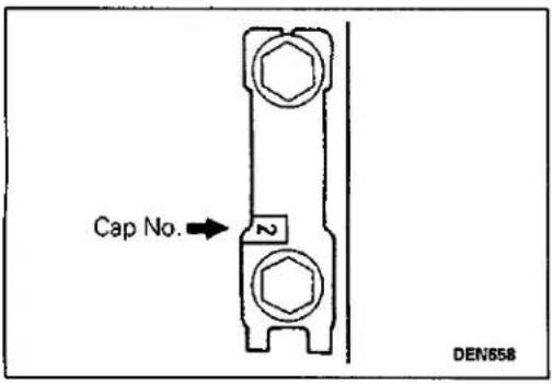
19. INSTALLATION OF CAMSHAFT BEARING CAP
The cap numbers are embossed on the top surface of the bearing caps, so install in the order of the numbers. However, no numbers are embossed on bearing caps 1 and 5.
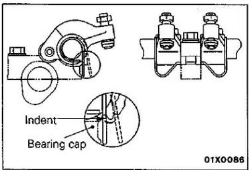
18. INSTALLATION OF ROCKER ARM AND SHAFT ASSEMBLY
(1) Install the rocker arm and shaft assembly to the bearing caps.
(2) Set the rocker arm springs into the bearing cap indents.
(3) Check the valve clearance and adjust if necessary. (Refer to P.11-xx.)
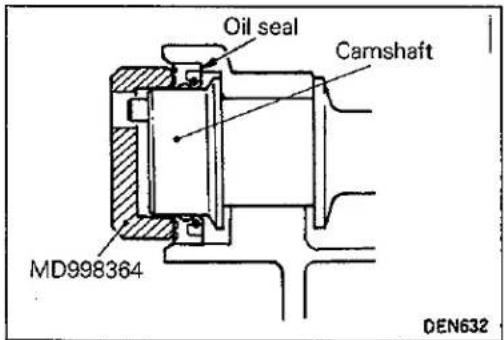
17. INSTALLATION OF CAMSHAFT OIL SEAL
(1) Apply a small amount of engine oil to the entire circumference of the oil seal lip and camshaft.
(2) Use the special tool to tap in the oil seal.
NOTE
The oil seal should be tapped in until the distance from the end of the camshaft to the end of the oil seal is as shown in the illustration.
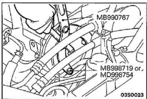
16. INSTALLATION OF CAMSHAFT SPROCKET
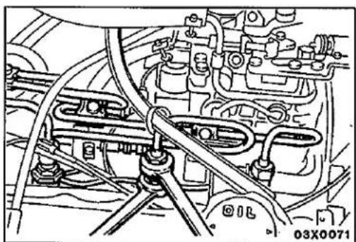
natural_image
Technical line drawing of an automotive engine bay with hoses and components (no readable text or symbols)15. INSTALLATION OF FUEL INJECTION PIPE
When tightening the nuts at both ends of the fuel injection pipe, hold the other side (pump-side delivery holder, nozzle-side nozzle holder) with a wrench, and tighten the nuts to the specified torque.
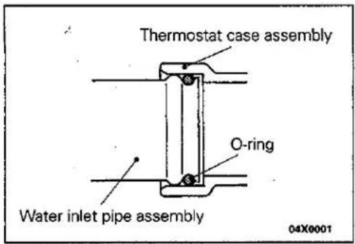
![Thermostat case assembly [Bead diameter 2.3-3.0 mm (10.09-0.12 in.)] 04X0011](/content/2026/05/858112/images/c27f83e9f0e3835143e6c361dc6bd93ece7e117926454b668dcd1edda566c676.jpg)
13. INSTALLATION OF THERMOSTAT CASE ASSEMBLY
(1) Insert the O-ring into the groove of the water inlet pipe assembly and rinse the outside of the O-ring with water.
(2) Apply specified sealant to the sections of the thermostat case assembly shown in the illustration.
Semi-dry sealant: Three bond 1207F
(3) After rinsing the inside of the thermostat case assembly with water, install the thermostat case assembly hole and the water inlet pipe.
(4) Tighten the thermostat case assembly mounting bolts.
TIMING BELT AND TIMING BELT B
REMOVAL AND INSTALLATION
Pre-removal and Post-installation Operations
- Removal and Installation of Left-side Under Cover
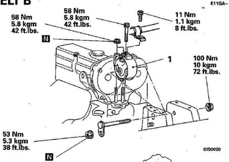
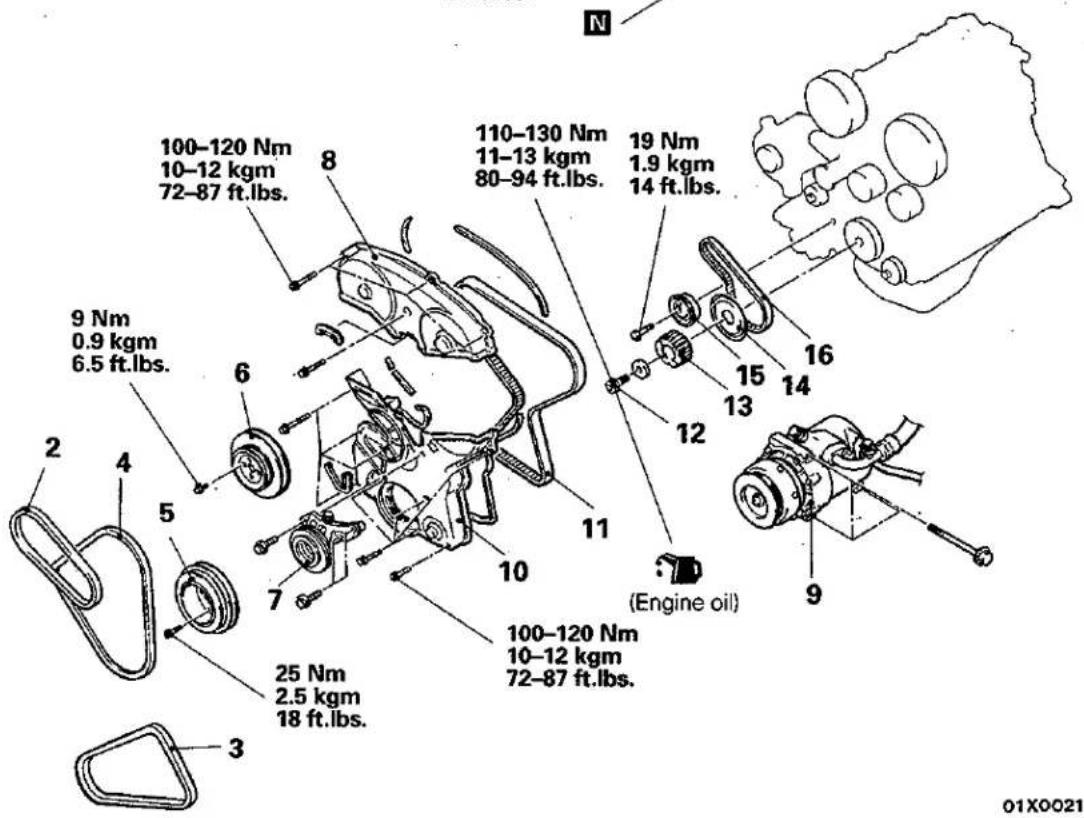
Timing belt removal steps
- Engine mount bracket
- Adjustment of drive belt tensions (Refer to P.11-79.)
- Power steering drive belt
- Air conditioner drive belt
- Alternator drive belt
- Crankshaft pulley
- Water pump pulley
- Air conditioner tensioner pulley assembly
- Timing belt upper cover
-
Air conditioner compressor connection
-
Timing belt lower cover
Adjustment of timing belt tension - Timing belt
Timing belt B removal steps
- Timing belt
- Crankshaft bolt
- Crankshaft sprocket
- Flange
- Timing belt B tensioner
Adjustment of timing belt B tension - Timing belt B
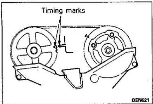
SERVICE POINTS OF REMOVAL
E11GBDL
11. REMOVAL OF TIMING BELT
(1) Align the timing marks.
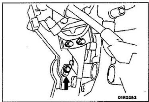
natural_image
Mechanical assembly diagram showing a hand adjusting components with an arrow indicating a specific part (no text or symbols present)(2) Using a long extension, loosen the installation bolt of the timing belt tensioner (from the engine rear).
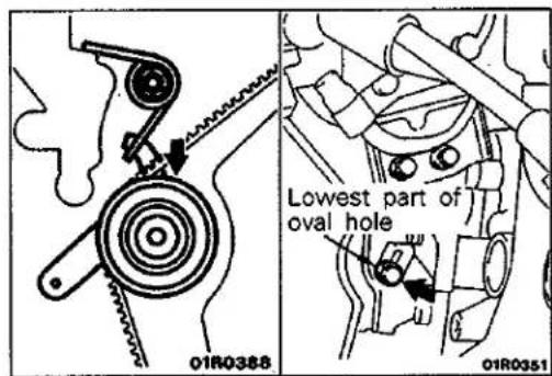
(3) Move the timing belt tensioner downward and loosely tighten the bolt so that the tensioner doesn't return; then remove the timing belt.
Caution
If the timing belt is to be re-used, use chalk to mark (on its flat side) an arrow indicating the clockwise direction.
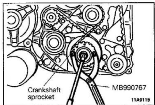
12./13. REMOVAL OF CRANKSHAFT SPROCKET AND CRANKSHAFT BOLT
16. REMOVAL OF TIMING BELT "B"
Caution
If the timing belt "B" is to be re-used, use chalk to mark (on its flat side) an arrow indicating the clockwise direction.
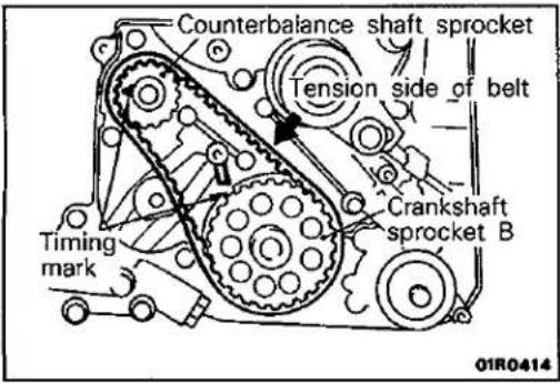
SERVICE POINTS OF INSTALLATION
E111DAH
16. INSTALLATION OF TIMING BELT "B"
(1) Ensure that crankshaft sprocket"B" timing mark and the counterbalance shaft sprocket timing mark are aligned.
(2) Fit timing belt "B" over crankshaft sprocket "B" and the counterbalance shaft sprocket. Ensure that there is no slack in the belt.
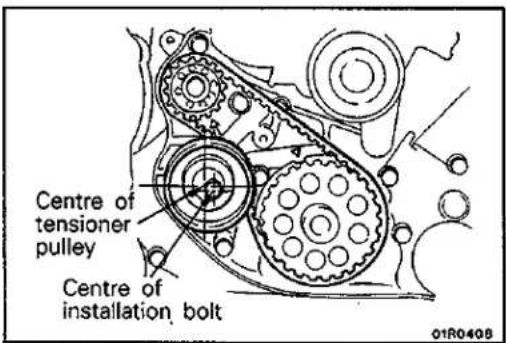
• ADJUSTMENT OF TIMING BELT "B" TENSION
(1) Temporarily fix the timing belt "B" tensioner such that the centre of the tensioner pulley is to the left and above the centre of the installation bolt, and temporarily attach the tensioner pulley so that the flange is toward the front of the engine.
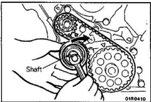
(2) Holding the timing belt "B" tensioner up with your finger in the direction of the arrow, place pressure on the timing belt so that the tension side of the belt is taut. Now tighten the bolt to fix the tensioner.
Caution
When tightening the bolt, ensure that the tensioner pulley shaft does not rotate with the bolt. Allowing it to rotate with the bolt can cause excessive tension of the belt.
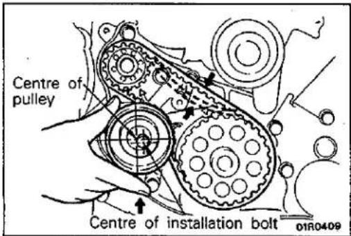
(3) Check to ensure that when centre of span on tension side is depressed with index finger in direction of arrow, tension of belt is up to specification.
Standard value: 5–7 mm (0.20–0.28 in.)
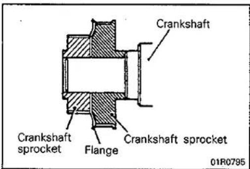
14./13./12. INSTALLATION OF FLANGE, CRANKSHAFT SPROCKET AND CRANKSHAFT BOLT
(1) When installing, be sure the direction is correct.
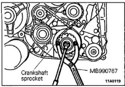
(2) Install the crankshaft sprocket by using the special tool.
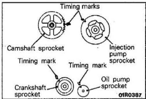
flowchart
graph TD
    A["Timing mark"] --> B["Camshaft sprocket"]
    A --> C["Crankshaft sprocket"]
    D["Injection pump sprocket"] --> E["Timing mark"]
    D --> F["Timing mark"]
    G["Oil pump sprocket"] --> H["End"]
11. INSTALLATION OF TIMING BELT
(1) Ensure that the timing marks of the camshaft sprocket, the injection pump sprocket, the crankshaft sprocket, and the oil pump sprocket are all aligned.
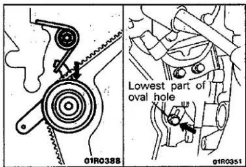
(2) Move the timing belt tensioner downward and loosely tighten the bolt so that the tensioner doesn't return.
(3) Install the timing belt onto the crankshaft sprocket, the timing belt idler, the camshaft sprocket, the injection pump sprocket, and the oil pump sprocket in that order.
Caution
If the timing belt is reused, install so that the arrow marked on it at the time of removal is pointing in the clockwise direction.
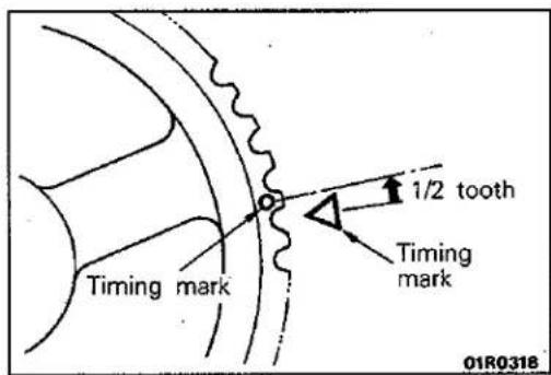
• ADJUSTMENT OF TIMING BELT TENSION
(1) Turn the crankshaft anticlockwise by a distance equivalent to 1/2 tooth of the camshaft sprocket in order to correct looseness at the timing belt idler side.
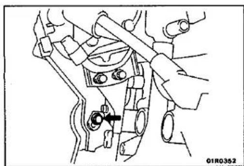
natural_image
Mechanical assembly diagram showing a lever mechanism with no visible text or symbols(2) Loosen (by 1/6 to 1/2 turn) the tensioner installation bolt previously secured provisionally, taking advantage of the force of the tensioner spring to provide tension to the belt.
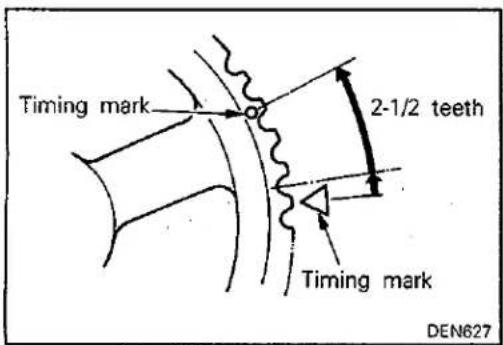
(3) In addition, turn the crankshaft anticlockwise by a distance equivalent to 2-1/2 teeth.
(4) Tighten the timing belt tensioner at the specified torque.
(5) Turn the crankshaft clockwise and align the timing mark.
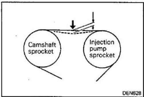
flowchart
graph TD
    A["Camshaft sprocket"] --> B["Injection pump sprocket"]
    style A fill:#fff,stroke:#000
    style B fill:#fff,stroke:#000
    style A -.-> C["Arrow down"]
    style B -.-> D["Arrow up"]
(6) Using the index finger, press between the camshaft sprocket and the injection pump and sprocket, and check whether or not the amount of flexion is within the standard value range or not.
Standard value range: 4–5 mm (0.16–0.20 in.)
ENGINE ASSEMBLY
REMOVAL AND INSTALLATION
E11TA--
Pre-removal Operations
(1) Removal of Hood (Refer to GROUP 42 - Hood)
(2) Prevention of Fuel Flow (Refer to GROUP 13 - Service Adjustment Procedures)
(3) Draining of Engine Coolant
(4) Removal of Transmission Assembly (Refer to GROUPS 22 and 23 - Transmission Assembly)
(5) Removal of Radiator Assembly (Refer to GROUP 14 – Radiator)
Post-installation Operations
(1) Installation of Radiator Assembly (Refer to Group 14 - Radiator)
(2) Installation of Transmission Assembly (Refer to GROUPS 22 and 23 - Transmission Assembly)
(3) Supplying of Engine Coolant
(4) Adjustment of Accelerator Cable (Refer to GROUP 13 - Service Adjustment Procedures.)
(5) Air Bleeding of Fuel Line (Refer to GROUP 13 - Service Adjustment Procedures)
(6) Installation of Hood (Refer to GROUP 42 - Hood)
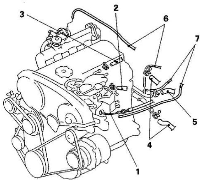
Removal steps
- Accelerator cable connection
- Fuel hose (return) connection
- Fuel hose (main) connection
- Heater hose connection
- Brake booster vacuum hose connection
- EGR vacuum hose connection
- Vacuum hose connection for air conditioner idle-up solenoid valve
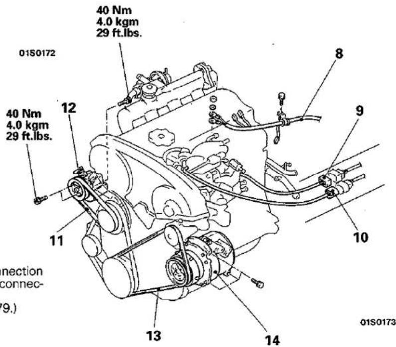
- Control harness connection
- Fuel injection pump harness connection
- Lever (throttle) position sensor connector
• Adjustment of drive belts (P.11-79.) - Power steering drive belt
- Power steering oil pump
- Air conditioner drive belt
- Air conditioner compressor
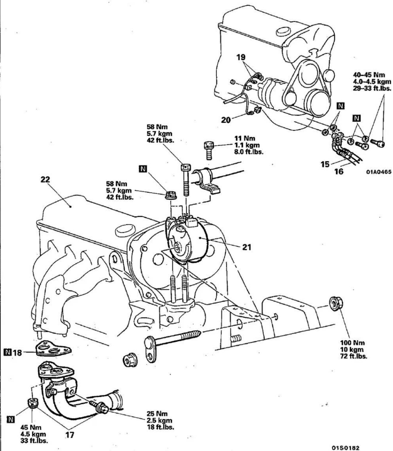
- Engine oil feed hose connection
- Engine oil return hose connection
- Self-locking nut and bolt
- Gasket
- Alternator connector
- Oil pressure switch connector
- Engine mount bracket
- Engine assembly
SERVICE POINTS OF REMOVAL
E11TBAN
12. REMOVAL OF POWER STEERING OIL PUMP
Remove the power steering oil pump from the bracket, with the hose attached.
NOTE
Place the removed power steering oil pump in a place where it will not be a hindrance when removing and installing the engine assembly, and tie it with a cord.
14. REMOVAL OF AIR CONDITIONER COMPRESSOR
Disconnect the air conditioner compressor connector and remove the compressor from the compressor bracket with the hose still attached.
NOTE
Place the removed air conditioner compressor in a place where it will not be a hindrance when removing and installing the engine assembly, and tie it with a cord.
21. REMOVAL OF ENGINE MOUNT BRACKET
(1) Support the engine with a garage jack.
(2) Hold the engine assembly with a chain block, etc.
(3) Place the garage jack against the engine oil pan with a piece of wood in between, and after raising the engine until there is no weight on the engine mount brackets, remove the engine mount brackets.
22. REMOVAL OF ENGINE ASSEMBLY
After checking that all cables, hoses and harness connectors, etc., are disconnected from the engine, lift the chain block slowly to remove the engine assembly upward from the engine compartment.
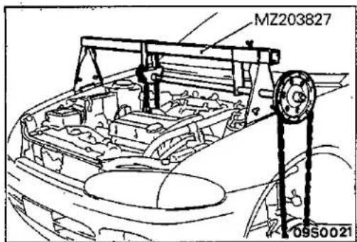
© Mitsubishi Motors Corporation
Jun. 1992
SERVICE POINTS OF INSTALLATION
E11TDAQ
21. INSTALLATION OF ENGINE MOUNT BRACKET
(1) Place a garage jack against the engine oil pan with a piece of wood in between, and install the engine mount bracket while adjusting the position of the engine.
(2) Support the engine with a garage jack.
(3) Remove the chain block and support the engine assembly with the special tool.
- ENGINE
- CONTENTS
- SPECIFICATIONS 2
- SPECIAL TOOLS 5
- ENGINE 7
- SERVICE ADJUSTMENT PROCEDURES .... 7
- CRANKSHAFT PULLEY 17
- CAMSHAFT AND CAMSHAFT OIL SEAL .... 18
- OIL PAN 20
- CRANKSHAFT OIL SEAL 22
- CYLINDER HEAD GASKET 24
- TIMING BELT 28
- ENGINE ASSEMBLY 30
- ENGINE 33
- SERVICE ADJUSTMENT PROCEDURES .... 33
- CRANKSHAFT PULLEY 42
- CAMSHAFT AND CAMSHAFT OIL SEAL 43
- CAMSHAFT AND CAMSHAFT OIL SEAL 45
- OIL PAN 48
- CRANKSHAFT OIL SEAL 50
- CYLINDER HEAD GASKET 54
- CYLINDER HEAD GASKET ..... 59
- TIMING BELT 64
- TIMING BELT 69
- ENGINE ASSEMBLY 73
- ENGINE ASSEMBLY 77
- ENGINE 79
- SERVICE ADJUSTMENT PROCEDURES .... 79
- CAMSHAFT AND CAMSHAFT OIL SEAL .... 90
- OIL PAN 92
- CRANKSHAFT FRONT OIL SEAL 94
- CRANKSHAFT REAR OIL SEAL 95
- CYLINDER HEAD GASKET 97
- TIMING BELT AND TIMING BELT B ..... 103
- ENGINE ASSEMBLY 108
- SPECIFICATIONS
- GENERAL SPECIFICATIONS
- SERVICE ADJUSTMENT PROCEDURES
- ALTERNATOR DRIVE BELT TENSION INSPECTION AND ADJUSTMENT E11FQBM
- ALTERNATOR DRIVE BELT TENSION INSPECTION
- ALTERNATOR DRIVE BELT TENSION ADJUSTMENT
- Standard value:
- POWER STEERING OIL PUMP DRIVE BELT TEN- SION INSPECTION AND ADJUSTMENT
- POWER STEERING OIL PUMP DRIVE BELT TENSION INSPECTION
- POWER STEERING OIL PUMP DRIVE BELT TENSION ADJUSTMENT
- AIR CONDITIONER COMPRESSOR DRIVE BELT TENSION INSPECTION AND ADJUSTMENT AIR CONDITIONER COMPRESSOR DRIVE BELT TENSION INSPECTION
- AIR CONDITIONER COMPRESSOR DRIVE BELT TENSION ADJUSTMENT
- VALVE CLEARANCE INSPECTION AND ADJUSTMENT E11FDAW
- IGNITION TIMING INSPECTION AND ADJUSTMENT E11FUBG
- Standard value: Approx. 10° BTDC
- NOTE
- IDLE SPEED INSPECTION
- Standard value: 5° BTDC ± 2°
- Curb idle speed: 750±100 r/min.
- IDLE MIXTURE INSPECTION
- Standard value
- COMPRESSION PRESSURE INSPECTION
- Caution
- Limit: max. 100 kPa (1.0 kg/cm², 14 psi)
- MANIFOLD VACUUM INSPECTION
- TIMING BELT TENSION ADJUSTMENT
- CRANKSHAFT PULLEY REMOVAL AND INSTALLATION
- Pre-removal and Installation Operation
- Removal steps
- SERVICE POINTS OF REMOVAL AND INSTALLATION E11LEAA
- CAMSHAFT AND CAMSHAFT OIL SEAL
- REMOVAL AND INSTALLATION
- Pre-removal and Post-installation Operation
- SERVICE POINTS OF REMOVAL
- REMOVAL OF CAMSHAFT SPROCKET
- SERVICE POINTS OF INSTALLATION
- INSTALLATION OF CAMSHAFT
- INSTALLATION OF OIL SEAL
- OIL PAN
- REMOVAL OF OIL PAN
- INSTALLATION OF OIL PAN
- INSTALLATION OF GASKET
- CRANKSHAFT OIL SEAL REMOVAL AND INSTALLATION
- Removal steps of crankshaft front oil seal
- Removal steps of crankshaft rear oil seal
- REMOVAL OF FLYWHEEL ASSEMBLY OR DRIVE PLATE
- INSTALLATION OF CRANKSHAFT REAR OIL SEAL
- INSTALLATION OF CRANKSHAFT FRONT OIL SEAL
- CYLINDER HEAD GASKET
- Pre-removal Operation
- Post-installation Operation
- REMOVAL OF TIMING BELT UPPER COVER
- REMOVAL OF CAMSHAFT SPROCKET
- REMOVAL OF CYLINDER HEAD ASSEMBLY
- INSTALLATION OF CYLINDER HEAD GASKET
- INSTALLATION OF CYLINDER HEAD ASSEMBLY
- TIMING BELT
- REMOVAL OF TIMING BELT UPPER COVER
- REMOVAL OF TIMING BELT
- INSTALLATION OF TIMING BELT
- INSTALLATION OF TIMING BELT LOWER COVER/ 1. TIMING BELT UPPER COVER
- ENGINE ASSEMBLY
- REMOVAL OF AIR CONDITIONER COMPRESSOR
- REMOVAL OF POWER STEERING OIL PUMP
- REMOVAL OF ENGINE ASSEMBLY
- INSTALLATION OF ENGINE ASSEMBLY
- ALTERNATOR DRIVE BELT TENSION INSPECTION AND ADJUSTMENT E11FQBN
- POWER STEERING OIL PUMP AND AIR CONDITIONER COMPRESSOR DRIVE BELT TENSION INSPECTION AND ADJUSTMENT
- VALVE CLEARANCE INSPECTION AND ADJUSTMENT E11FDBZ
- IGNITION TIMING INSPECTION AND ADJUSTMENT E11FUBK
- Standard value: 5° BTDC ±2°
- CO concentration: 0.5% or less
- HC concentration: 100 ppm or less
- Standard value: Approx. 33 mm (1.30 in.)
- LASH ADJUSTERS CHECK
- CRANKSHAFT PULLEY
- REMOVAL OF CRANKSHAFT PULLEY BOLT
- INSTALLATION OF CRANKSHAFT PULLEY WASHER/3. CRANKSHAFT PULLEY BOLT
- REMOVAL OF CAMSHAFT SPROCKET
- INSTALLATION OF CAMSHAFT OIL SEAL
- REMOVAL OF CAMSHAFT SPROCKET
- INSTALLATION OF CAMSHAFT
- INSTALLATION OF BEARING CAP
- REMOVAL OF TRANSFER ASSEMBLY
- REMOVAL OF OIL PAN
- INSTALLATION OF DRAIN PLUG GASKET
- Crankshaft front oil seal removal steps
- Crankshaft rear oil seal removal steps
- REMOVAL OF FLYWHEEL ASSEMBLY OR DRIVE PLATE
- INSTALLATION OF CRANKSHAFT REAR OIL SEAL
- INSTALLATION OF FLYWHEEL ASSEMBLY OR DRIVE PLATE
- Specified sealant: 3M Stud locking 4170 or equivalent
- INSTALLATION OF CRANKSHAFT FRONT OIL SEAL
- REMOVAL OF CAMSHAFT SPROCKET
- REMOVAL OF CYLINDER HEAD ASSEMBLY
- INSTALLATION OF CYLINDER HEAD GASKET
- INSTALLATION OF CYLINDER HEAD ASSEMBLY/34. WASHER/33. CYLINDER HEAD BOLT
- INSTALLATION OF WATER INLET FITTING, THERMOSTAT AND THERMOSTAT CASE ASSEMBLY
- √ 30. INSTALLATION OF CYLINDER HEAD ASSEMBLY/29. CYLINDER HEAD BOLT
- INSTALLATION OF WATER INLET FITTING, THERMOSTAT AND THERMOSTAT CASE ASSEMBLY
- REMOVAL OF CRANKSHAFT BOLT/5. CRANKSHAFT PULLEY
- REMOVAL OF TIMING BELT
- INSTALLATION OF TIMING BELT
- • ADJUSTMENT OF TIMING BELT TENSION
- INSTALLATION OF FLANGE
- INSTALLATION OF TIMING BELT LOWER COVER/6. TIMING BELT UPPER COVER
- INSTALLATION OF CRANKSHAFT PULLEY/4. CRANKSHAFT BOLT
- REMOVAL OF TIMING BELT
- INSTALLATION OF AUTO TENSIONER
- INSTALLATION OF TIMING BELT
- Standard value: 3.8–4.5 mm (0.15–0.17 in)
- INSTALLATION OF TIMING BELT LOWER COVER/2. TIMING BELT UPPER COVER
- REMOVAL OF AIR CONDITIONER COMPRESSOR
- REMOVAL OF ENGINE MOUNT BRACKET
- REMOVAL OF ENGINE ASSEMBLY
- INSTALLATION OF ENGINE ASSEMBLY
- INSTALLATION OF ENGINE MOUNT BRACKET
- DRIVE BELT TENSION INSPECTION AND ADJUSTMENT E11F0BQ
- DRIVE BELT TENSION INSPECTION
- DRIVE BELT TENSION ADJUSMENT
- ALTERNATOR DRIVE BELT
- Tightening torque
- POWER STEERING OIL PUMP DRIVE BELT
- VALVE CLEARANCE INSPECTION AND ADJUSTMENT E11FDAX
- Standard value (hot engine):
- Specified sealant: 3M ATD Part No. 8660 or equivalent
- INJECTION TIMING ADJUSTMENT
- ENGINE IDLE SPEED INSPECTION AND ADJUSTMENT
- Limit: max. 300 kPa (3.0 kg/cm, 43 psi)
- Tightening torque: 55 Nm (5.5 kgm, 40 ft.lbs.)
- TIMING BELT ADJUSTMENT
- Standard value range: 4.0–5.0 mm (0.16–0.20 in.)
- REMOVAL OF CAMSHAFT SPROCKET
- INSTALLATION OF CAMSHAFT BEARING CAP
- INSTALLATION OF ROCKER ARM AND SHAFT ASSEMBLY
- INSTALLATION OF CAMSHAFT OIL SEAL
- INSTALLATION OF CAMSHAFT SPROCKET
- INSTALLATION OF GASKET
- CRANKSHAFT FRONT OIL SEAL
- INSTALLATION OF CRANKSHAFT FRONT OIL SEAL
- CRANKSHAFT REAR OIL SEAL
- Pre-removal and Post-installation Operations
- REMOVAL OF FLYWHEEL BOLT /3. DRIVE PLATE BOLT
- INSTALLATION OF CRANKSHAFT REAR OIL SEAL
- INSTALLATION OF DRIVE PLATE BOLT /1. FLYWHEEL BOLT
- DISCONNECTION OF INJECTION PIPE
- REMOVAL OF CAMSHAFT SPROCKET
- REMOVAL OF CYLINDER HEAD BOLT
- INSTALLATION OF CYLINDER HEAD GASKET
- INSTALLATION OF CYLINDER HEAD BOLT
- INSTALLATION OF CAMSHAFT BEARING CAP
- INSTALLATION OF ROCKER ARM AND SHAFT ASSEMBLY
- INSTALLATION OF CAMSHAFT OIL SEAL
- INSTALLATION OF CAMSHAFT SPROCKET
- INSTALLATION OF FUEL INJECTION PIPE
- INSTALLATION OF THERMOSTAT CASE ASSEMBLY
- Semi-dry sealant: Three bond 1207F
- TIMING BELT AND TIMING BELT B
- Timing belt removal steps
- Timing belt B removal steps
- REMOVAL OF TIMING BELT
- 12./13. REMOVAL OF CRANKSHAFT SPROCKET AND CRANKSHAFT BOLT
- REMOVAL OF TIMING BELT "B"
- INSTALLATION OF TIMING BELT "B"
- • ADJUSTMENT OF TIMING BELT "B" TENSION
- 14./13./12. INSTALLATION OF FLANGE, CRANKSHAFT SPROCKET AND CRANKSHAFT BOLT
- INSTALLATION OF TIMING BELT
- Pre-removal Operations
- Post-installation Operations
- REMOVAL OF POWER STEERING OIL PUMP
- REMOVAL OF AIR CONDITIONER COMPRESSOR
- REMOVAL OF ENGINE MOUNT BRACKET
- REMOVAL OF ENGINE ASSEMBLY
- INSTALLATION OF ENGINE MOUNT BRACKET
Mærke : MITSUBISHI
Model : Colt (1992)
Kategori : Bil