LGA1700 LC1 Upgrade Kit - Computer tilbehør SilentiumPC - Gratis brugsanvisning og manual
Find enhedens vejledning gratis LGA1700 LC1 Upgrade Kit SilentiumPC i PDF-format.

Brugerspørgsmål om LGA1700 LC1 Upgrade Kit SilentiumPC
0 spørgsmål om dette apparat. Besvar dem du kender, eller stil dit eget.
Stil et nyt spørgsmål om dette apparat
Download vejledningen til din Computer tilbehør i PDF-format gratis! Find din vejledning LGA1700 LC1 Upgrade Kit - SilentiumPC og tag din elektroniske enhed tilbage i hånden. På denne side er alle dokumenter nødvendige for brugen af din enhed offentliggjort. LGA1700 LC1 Upgrade Kit af mærket SilentiumPC.
BRUGSANVISNING LGA1700 LC1 Upgrade Kit SilentiumPC
Accessories / Akcesoria
A
日
c

B

E

F
T

PH

P

Comparison of Navis' frames
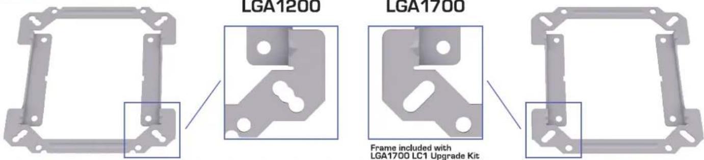
LGA1200
LGA1700
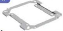
Frame included with LGA1700 LC1 Upgrade Kit
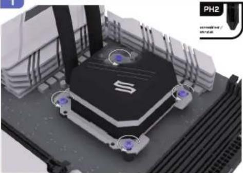
1
natural_image
3D rendering of a mechanical device with purple components and a labeled part 'PH2' (no readable text or symbols beyond labels)2
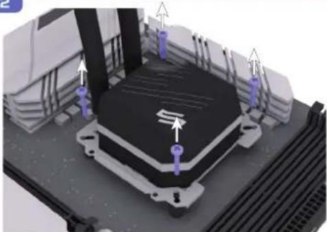
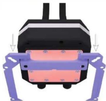
natural_image
3D mechanical assembly diagram showing a base platform with mounting brackets and directional arrows (no text or symbols)3
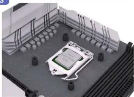
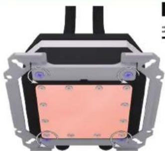
natural_image
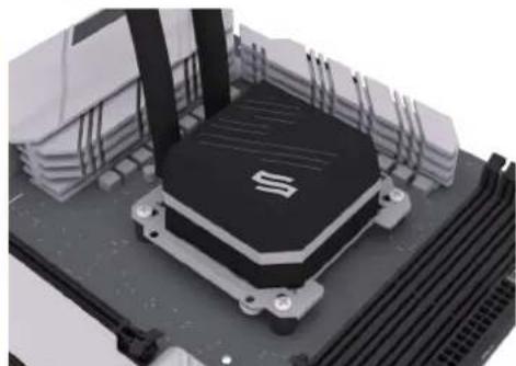
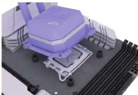
3D rendering of a microchip mounted on a platform with surrounding hardware (no visible text or symbols)4
natural_image
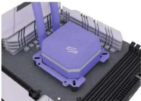
3D diagram of a mechanical or electronic component with no visible text, numbers, or symbols5
natural_image
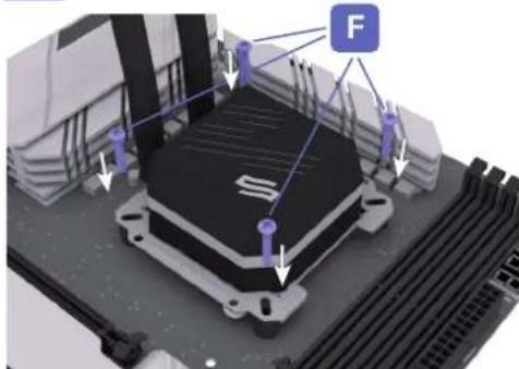
Diagram of a mechanical assembly with labeled components and directional arrows (no readable text or symbols)6
natural_image
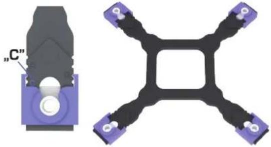
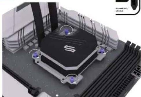
Diagram of a mechanical component with purple and pink parts, showing directional arrows (no text or symbols)7

8
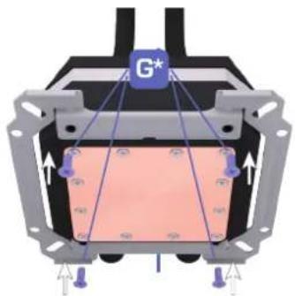
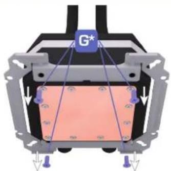
natural_image
Cross-sectional diagram of a mechanical or electrical component with labeled G* and directional arrows (no readable text or symbols)9
natural_image
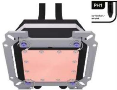
Cross-sectional diagram of a mechanical or electronic component with labeled part PH1 (no readable text or symbols beyond label)10A
natural_image
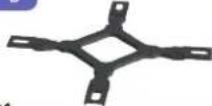
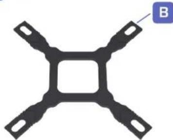
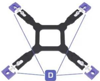
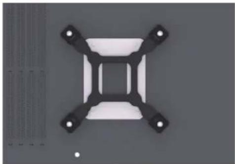
Pure mechanical component diagram with four symmetrical arms and a central square cutout (no text or symbols)10B
flowchart
graph TD
    A["Sensor 1"] --> B["Central Control Unit"]
    C["Sensor 2"] --> B
    D["Sensor 3"] --> B
    E["Sensor 4"] --> B
    F["Sensor 5"] --> B
    G["Sensor 6"] --> B
    H["Sensor 7"] --> B
    I["Sensor 8"] --> B
    J["Sensor 9"] --> B
    K["Sensor 10"] --> B
    L["Sensor 11"] --> B
    M["Sensor 12"] --> B
    N["Sensor 13"] --> B
    O["Sensor 14"] --> B
    P["Sensor 15"] --> B
    Q["Sensor 16"] --> B
    R["Sensor 17"] --> B
    S["Sensor 18"] --> B
    T["Sensor 19"] --> B
    U["Sensor 20"] --> B
    V["Sensor 21"] --> B
    W["Sensor 22"] --> B
    X["Sensor 23"] --> B
    Y["Sensor 24"] --> B
    Z["Sensor 25"] --> B
    AA["Sensor 26"] --> B
    AB["Sensor 27"] --> B
    AC["Sensor 28"] --> B
    AD["Sensor 29"] --> B
    AE["Sensor 30"] --> B
    AF["Sensor 31"] --> B
    AG["Sensor 32"] --> B
    AH["Sensor 33"] --> B
    AI["Sensor 34"] --> B
    AJ["Sensor 35"] --> B
    AK["Sensor 36"] --> B
    AL["Sensor 37"] --> B
    AM["Sensor 38"] --> B
    AN["Sensor 39"] --> B
    AO["Sensor 40"] --> B
    AP["Sensor 41"] --> B
    AQ["Sensor 42"] --> B
    AR["Sensor 43"] --> B
    AS["Sensor 44"] --> B
    AT["Sensor 45"] --> B
    AU["Sensor 46"] --> B
    AV["Sensor 47"] --> B
    AW["Sensor 48"] --> B
    AX["Sensor 49"] --> B
    AY["Sensor 50"] --> B
10C
natural_image
Pure mechanical component diagram with four arms and central square (no text or symbols)10D
natural_image
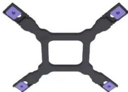
Symmetrical mechanical or electrical component diagram with four arms and a central square, connected by purple connectors (no text or symbols)10E
natural_image
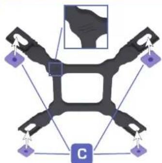
Technical diagram showing a mechanical component labeled 'C' and a cross-shaped structure with four arms (no text or symbols beyond label)10F

natural_image
Black four-angle screwdriver with a green checkmark indicating selection (no text or symbols)LGA1700: MARKINGS „A“, „B“ AND „C“ VISIBLE / ZNAKI „A“, „B“ I „C“ WIDOCZNE
11
natural_image
Pure electrical circuit lines without any symbols12

natural_image
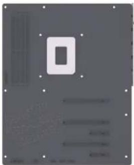
Simple geometric shape with a rectangular cutout on a gray background, surrounded by small dots (no text or symbols)13
natural_image
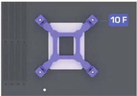
3D rendered purple mechanical component with four arms and a central square cutout, labeled '10 F' (no other text or symbols)14
natural_image
Top-down view of a mechanical component with four symmetric arms and central square cutout (no text or symbols)15
natural_image
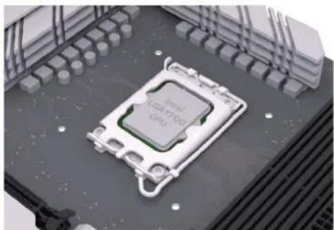
3D rendering of an Intel LOGATCO CPU chip mounted on a circuit board (no text or symbols visible)16
natural_image
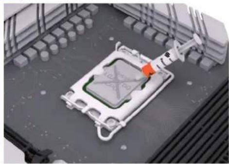
3D rendering of a robotic arm interacting with a mechanical component on a platform (no visible text or symbols)17
natural_image
3D rendering of a microchip with surrounding components and no visible text or symbols18
natural_image
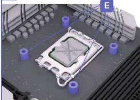
3D rendering of a purple robotic device mounted on a black CPU socket (no visible text or symbols)19
natural_image
3D rendering of a purple industrial machine component with cooling fins and mounting brackets (no visible text or symbols)20
21
natural_image
3D rendering of a computer processor with visible CPU socket and drive slots (no text or symbols)22