R-78K5.0-1.0 - Lyd/video konverter Recom - Gratis brugsanvisning og manual
Find enhedens vejledning gratis R-78K5.0-1.0 Recom i PDF-format.

Brugerspørgsmål om R-78K5.0-1.0 Recom
0 spørgsmål om dette apparat. Besvar dem du kender, eller stil dit eget.
Stil et nyt spørgsmål om dette apparat
Download vejledningen til din Lyd/video konverter i PDF-format gratis! Find din vejledning R-78K5.0-1.0 - Recom og tag din elektroniske enhed tilbage i hånden. På denne side er alle dokumenter nødvendige for brugen af din enhed offentliggjort. R-78K5.0-1.0 af mærket Recom.
BRUGSANVISNING R-78K5.0-1.0 Recom
Features
• Efficiency up to 95%, no need for heatsinks
• 4.5 - 36VDC wide input voltage
- -40°C to +90°C ambient operation without derating
- Pin compatible with 78 series regulators
• Non isolated DC/DC converter
- Undervoltage and short circuit protection
Switching Regulator
Description
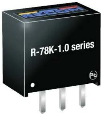
The R-78K-1.0 series is a switching regulator module that has been designed to offer all the advantages of a switching regulator (high efficiency, wide input range, accurate output voltage regulation) but with a low cost for production quantities. Due to the R-78K-1.0's high efficiency of up to 95% no heat-sink is required, and operation from -40 to 90°C is possible with slight derating. The compact TO-220 compatible SIP3 package measures only 11.5 x 7.55 x 10.2mm, so it saves precious board space.
Selection Guide
| Part Number | Input Voltage Range [VDC] | Output Voltage [VDC] | Output Current [mA] | Efficiency @ min. Vin [%] | @ max. Vin [%] |
| R-78K1.8-1.0 | 4.5 - 36 | 1.8 | 1000 | 83 | 71 |
| R-78K2.5-1.0 | 4.5 - 36 | 2.5 | 1000 | 85 | 75 |
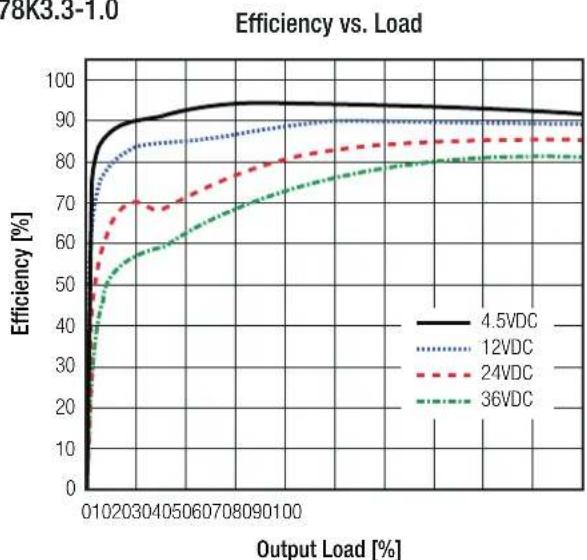
| R-78K3.3-1.0 | 4.5 - 36 | 3.3 | 1000 | 88 | 79 |
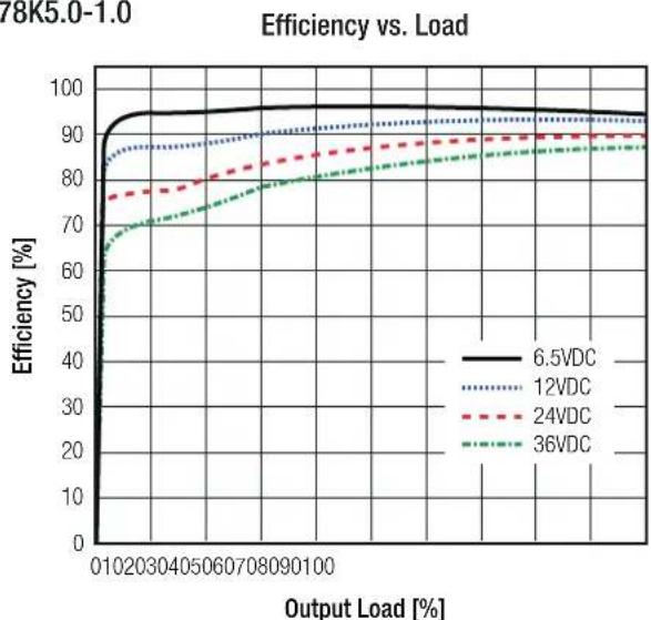
| R-78K5.0-1.0 | 6.5 - 36 | 5 | 1000 | 92 | 85 |
| R-78K9.0-1.0 | 12 - 36 | 9 | 1000 | 93 | 89 |
| R-78K12-1.0 | 15 - 36 | 12 | 1000 | 95 | 91 |
| R-78K15-1.0 | 18 - 36 | 15 | 1000 | 94 | 91 |
R-78K-1.0
1.0 Amp
SIP3

Single Output


IEC/EN62368-1 3rd Edition certified
EN55032 compliant
CB-Report
Model Numbering

Specifications
ABSOLUTE MAX RATINGS (exceeding these ratings may damage the device)
| Parameter Condition Min. Typ. Max. | ||||
| Maximum Input Voltage Slew Rate (1) | +VIN to GND 10VDC/μs | |||
| Case Temperature | -40°C 110°C | |||
| Storage Temperature | -50°C 125°C | |||
Notes:
| Note1: At higher slew rates or hard plugging, add 27μF E-Cap between +Vin and GND, especially when Vin is >18VDC |
Specifications (measured @ Ta= -40°C to +90°C, V _th = 24VDC, full load and after warm-up unless otherwise stated)
BASIC CHARACTERISTICS
| Parameter Condition Min. Typ. Max. | |||||
| Input Under Voltage Lockout (UVLO) | R-78K1.8-1.0, R-78K2.5-1.0,R-78K3.3-1.0 | DC-DC ON | 3.75VDC 4 | 05VDC | |
| DC-DC OFF | 3.6VDC 3.8VDC | ||||
| R-78K5.0-1.0 | DC-DC ON | 5VDC 5.25VDC | |||
| DC-DC OFF | 4.6VDC 4.9VDC | ||||
| R-78K9.0-1.0 | DC-DC ON | 9.5VDC 10 | .5VDC | ||
| DC-DC OFF | 9.1VDC 9.7VDC | ||||
| R-78K12-1.0 | DC-DC ON | 13.0VDC 13 | .5VDC | ||
| DC-DC OFF | 12.5VDC 13 | .1VDC | |||
| R-78K15-1.0 | DC-DC ON 16.9VDC 17 | .5VDC | |||
| DC-DC OFF 15.6VDC 16 | .6VDC | ||||
| Quiescent Current | 1mA | ||||
| Internal Switching Frequency | 400kHz | ||||
| Minimum Load 0% | |||||
| Output Ripple and Noise | 20MHz BW | R-78K1.8-1.0 - R-78K5.0-1.0 | 50mVp-p | ||
| R-78K9.0-1.0 | 60mVp-p | ||||
| R-78K12-1.0 | 75mVp-p | ||||
| R-78K15-1.0 | 100mVp-p | ||||
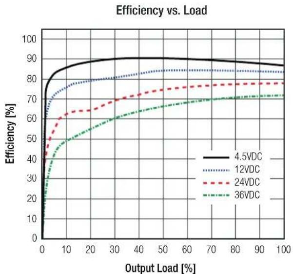
R-78K1.8-1.0
line
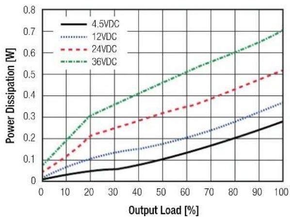
| Output Load [%] | 4.5VDC | 12VDC | 24VDC | 36VDC | | --------------- | ------ | ----- | ----- | ----- | | 0 | 0 | 0 | 0 | 0 | | 10 | 85 | 75 | 60 | 45 | | 20 | 88 | 78 | 65 | 55 | | 30 | 89 | 80 | 70 | 60 | | 40 | 89 | 82 | 72 | 65 | | 50 | 89 | 83 | 75 | 68 | | 60 | 89 | 84 | 76 | 70 | | 70 | 89 | 84 | 77 | 71 | | 80 | 89 | 84 | 77 | 72 | | 90 | 89 | 84 | 77 | 72 | | 100 | 89 | 84 | 77 | 72 |Power Dissipation vs. Load
line
| Output Load [%] | 4.5VDC | 12VDC | 24VDC | 36VDC | | --------------- | ------ | ----- | ----- | ----- | | 0 | 0.0 | 0.0 | 0.0 | 0.0 | | 10 | 0.05 | 0.08 | 0.1 | 0.15 | | 20 | 0.07 | 0.12 | 0.2 | 0.3 | | 30 | 0.08 | 0.15 | 0.25 | 0.35 | | 40 | 0.1 | 0.18 | 0.3 | 0.4 | | 50 | 0.12 | 0.2 | 0.35 | 0.45 | | 60 | 0.15 | 0.22 | 0.4 | 0.5 | | 70 | 0.18 | 0.25 | 0.45 | 0.55 | | 80 | 0.2 | 0.28 | 0.5 | 0.6 | | 90 | 0.22 | 0.3 | 0.55 | 0.65 | | 100 | 0.25 | 0.35 | 0.6 | 0.7 |continued on next page
Specifications (measured @ Ta= -40°C to +90°C, V_th=24VDC , full load and after warm-up unless otherwise stated)
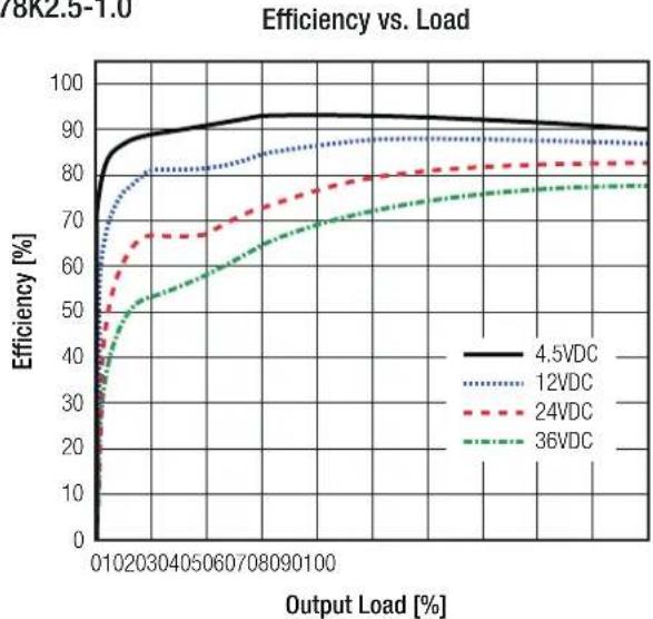
R-78K2.5-1.0
line
| Output Load [%] | 4.5VDC | 12VDC | 24VDC | 36VDC | | --------------- | ------ | ----- | ----- | ----- | | 01 | 85 | 80 | 65 | 50 | | 20 | 90 | 85 | 70 | 55 | | 30 | 92 | 88 | 75 | 60 | | 40 | 93 | 89 | 78 | 65 | | 50 | 94 | 90 | 80 | 70 | | 60 | 94 | 90 | 82 | 72 | | 70 | 94 | 90 | 83 | 74 | | 80 | 94 | 90 | 84 | 75 | | 90 | 94 | 90 | 85 | 76 | | 100 | 94 | 90 | 85 | 77 |Power Dissipation vs. Load
line
| Output Load [%] | 4.5VDC | 12VDC | 24VDC | 36VDC | | --------------- | ------ | ----- | ----- | ----- | | 0 | 0.0 | 0.0 | 0.0 | 0.0 | | 10 | 0.05 | 0.08 | 0.12 | 0.25 | | 20 | 0.07 | 0.12 | 0.20 | 0.38 | | 30 | 0.08 | 0.15 | 0.25 | 0.45 | | 40 | 0.10 | 0.18 | 0.30 | 0.50 | | 50 | 0.12 | 0.20 | 0.35 | 0.55 | | 60 | 0.15 | 0.22 | 0.40 | 0.60 | | 70 | 0.18 | 0.25 | 0.45 | 0.65 | | 80 | 0.22 | 0.28 | 0.50 | 0.70 | | 90 | 0.25 | 0.32 | 0.55 | 0.75 | | 100 | 0.30 | 0.38 | 0.60 | 0.80 |R-78K3.3-1.0
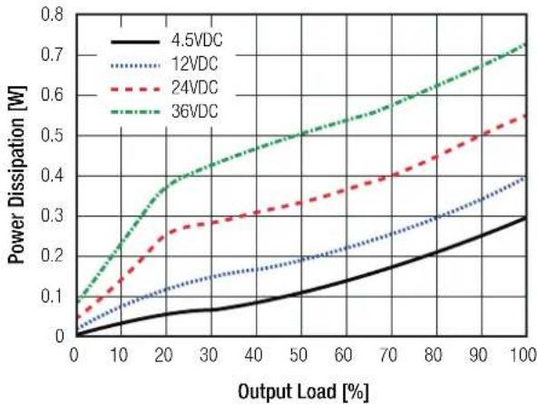
Power Dissipation vs. Load
line
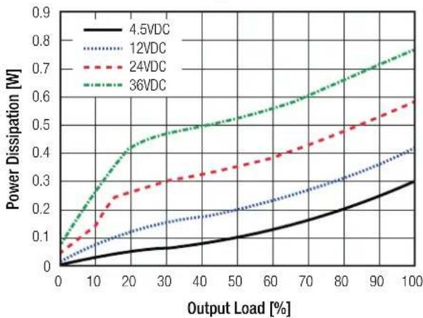
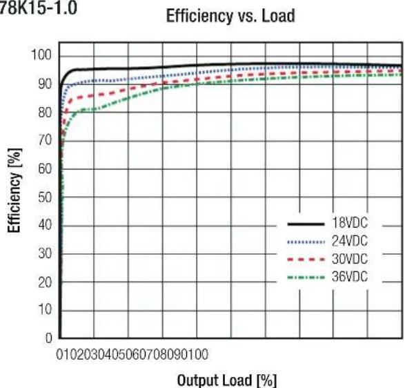
| Output Load [%] | 4.5VDC | 12VDC | 24VDC | 36VDC | | --------------- | ------ | ----- | ----- | ----- | | 0 | 0.0 | 0.0 | 0.0 | 0.0 | | 10 | 0.05 | 0.08 | 0.15 | 0.25 | | 20 | 0.08 | 0.12 | 0.25 | 0.45 | | 30 | 0.1 | 0.15 | 0.3 | 0.5 | | 40 | 0.12 | 0.18 | 0.35 | 0.55 | | 50 | 0.15 | 0.2 | 0.4 | 0.6 | | 60 | 0.18 | 0.22 | 0.45 | 0.65 | | 70 | 0.2 | 0.25 | 0.5 | 0.7 | | 80 | 0.22 | 0.28 | 0.55 | 0.75 | | 90 | 0.25 | 0.3 | 0.6 | 0.8 | | 100 | 0.3 | 0.35 | 0.65 | 0.85 |R-78K5.0-1.0
line
| Output Load [%] | 6.5VDC | 12VDC | 24VDC | 36VDC | | --------------- | ------ | ----- | ----- | ----- | | 010 | 95 | 85 | 75 | 65 | | 20 | 96 | 87 | 77 | 70 | | 30 | 96 | 88 | 78 | 72 | | 40 | 96 | 89 | 79 | 74 | | 50 | 96 | 90 | 80 | 76 | | 60 | 96 | 90 | 81 | 78 | | 70 | 96 | 91 | 82 | 80 | | 80 | 96 | 91 | 83 | 82 | | 90 | 96 | 92 | 84 | 84 | | 100 | 96 | 92 | 85 | 86 | | Final | 95 | 91 | 84 | 85 |Power Dissipation vs. Load

line
| Output Load [%] | 6.5VDC | 12VDC | 24VDC | 36VDC | | --------------- | ------ | ----- | ----- | ----- | | 0 | 0.0 | 0.0 | 0.0 | 0.0 | | 10 | 0.05 | 0.08 | 0.15 | 0.35 | | 20 | 0.07 | 0.12 | 0.22 | 0.40 | | 30 | 0.08 | 0.14 | 0.28 | 0.42 | | 40 | 0.09 | 0.15 | 0.30 | 0.45 | | 50 | 0.10 | 0.16 | 0.32 | 0.48 | | 60 | 0.12 | 0.18 | 0.35 | 0.52 | | 70 | 0.15 | 0.20 | 0.38 | 0.55 | | 80 | 0.18 | 0.22 | 0.42 | 0.60 | | 90 | 0.22 | 0.25 | 0.45 | 0.65 | | 100 | 0.28 | 0.35 | 0.50 | 0.70 |continued on next page
Specifications (measured @ Ta= -40°C to +90°C, V _in = 24VDC, full load and after warm-up unless otherwise stated)
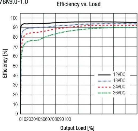
R-78K9.0-1.0
line
| Output Load [%] | 12VDC | 18VDC | 24VDC | 36VDC | | --------------- | ----- | ----- | ----- | ----- | | 010 | 95 | 90 | 85 | 70 | | 20 | 95 | 90 | 85 | 75 | | 30 | 95 | 90 | 85 | 78 | | 40 | 95 | 90 | 85 | 80 | | 50 | 95 | 90 | 85 | 82 | | 60 | 95 | 90 | 85 | 84 | | 70 | 95 | 90 | 85 | 86 | | 80 | 95 | 90 | 85 | 88 | | 90 | 95 | 90 | 85 | 90 | | 100 | 95 | 90 | 85 | 90 |Power Dissipation vs. Load
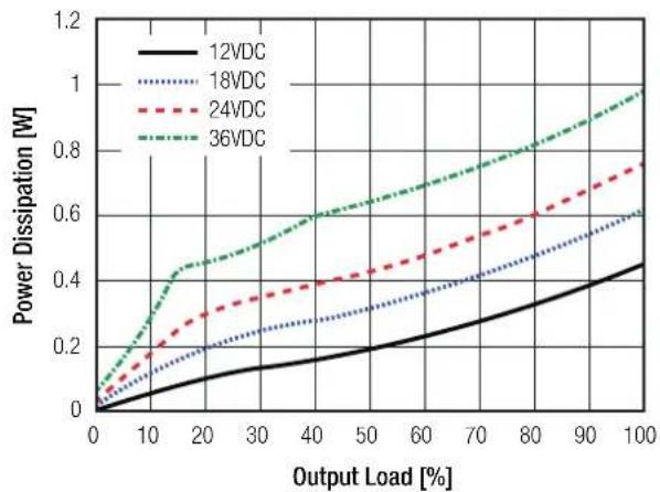
line
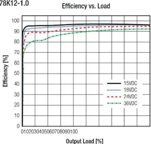
| Output Load [%] | 12VDC | 18VDC | 24VDC | 36VDC | | --------------- | ----- | ----- | ----- | ----- | | 0 | 0.0 | 0.0 | 0.0 | 0.0 | | 10 | 0.1 | 0.15 | 0.2 | 0.3 | | 20 | 0.15 | 0.2 | 0.3 | 0.45 | | 30 | 0.2 | 0.25 | 0.35 | 0.5 | | 40 | 0.25 | 0.3 | 0.4 | 0.6 | | 50 | 0.3 | 0.35 | 0.45 | 0.65 | | 60 | 0.35 | 0.4 | 0.5 | 0.7 | | 70 | 0.4 | 0.45 | 0.55 | 0.75 | | 80 | 0.45 | 0.5 | 0.6 | 0.8 | | 90 | 0.5 | 0.55 | 0.65 | 0.85 | | 100 | 0.55 | 0.6 | 0.7 | 0.95 |R-78K12-1.0
line
| Output Load [%] | 15VDC | 18VDC | 24VDC | 36VDC | | --------------- | ----- | ----- | ----- | ----- | | 01 | 95 | 94 | 90 | 75 | | 20 | 96 | 95 | 91 | 78 | | 30 | 96 | 95 | 91 | 80 | | 40 | 96 | 95 | 91 | 82 | | 50 | 96 | 95 | 91 | 84 | | 60 | 96 | 95 | 91 | 86 | | 70 | 96 | 95 | 91 | 88 | | 80 | 96 | 95 | 91 | 90 | | 90 | 96 | 95 | 91 | 91 | | 100 | 96 | 95 | 91 | 92 |Power Dissipation vs. Load
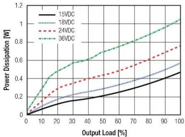
line
| Output Load [%] | 15VDC | 18VDC | 24VDC | 36VDC | | --------------- | ----- | ----- | ----- | ----- | | 0 | 0.0 | 0.0 | 0.0 | 0.0 | | 10 | 0.1 | 0.1 | 0.15 | 0.3 | | 20 | 0.15 | 0.15 | 0.25 | 0.5 | | 30 | 0.2 | 0.2 | 0.35 | 0.6 | | 40 | 0.25 | 0.25 | 0.4 | 0.7 | | 50 | 0.3 | 0.3 | 0.45 | 0.75 | | 60 | 0.35 | 0.35 | 0.5 | 0.8 | | 70 | 0.4 | 0.4 | 0.55 | 0.85 | | 80 | 0.45 | 0.45 | 0.6 | 0.9 | | 90 | 0.5 | 0.5 | 0.65 | 0.95 | | 100 | 0.55 | 0.55 | 0.7 | 1.0 |R-78K15-1.0
line
| Output Load [%] | 18VDC | 24VDC | 30VDC | 36VDC | | --------------- | ----- | ----- | ----- | ----- | | 010 | 95 | 90 | 85 | 80 | | 20 | 97 | 92 | 88 | 83 | | 30 | 98 | 93 | 89 | 84 | | 40 | 98 | 93 | 89 | 84 | | 50 | 98 | 93 | 89 | 84 | | 60 | 98 | 93 | 89 | 84 | | 70 | 98 | 93 | 89 | 84 | | 80 | 98 | 93 | 89 | 84 | | 90 | 98 | 93 | 89 | 84 | | 100 | 98 | 93 | 89 | 84 |Power Dissipation vs. Load
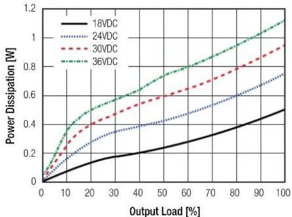
line
| Output Load [%] | 18VDC | 24VDC | 30VDC | 36VDC | | --------------- | ----- | ----- | ----- | ----- | | 0 | 0.0 | 0.0 | 0.0 | 0.0 | | 10 | 0.1 | 0.2 | 0.3 | 0.4 | | 20 | 0.15 | 0.3 | 0.4 | 0.5 | | 30 | 0.2 | 0.35 | 0.5 | 0.6 | | 40 | 0.25 | 0.4 | 0.6 | 0.7 | | 50 | 0.3 | 0.45 | 0.65 | 0.8 | | 60 | 0.35 | 0.5 | 0.7 | 0.9 | | 70 | 0.4 | 0.55 | 0.75 | 1.0 | | 80 | 0.45 | 0.6 | 0.8 | 1.1 | | 90 | 0.5 | 0.65 | 0.85 | 1.2 | | 100 | 0.55 | 0.7 | 0.9 | 1.3 |Specifications (measured @ Ta= -40°C to +90°C, V_th=24VDC , full load and after warm-up unless otherwise stated)
REGULATIONS
| Parameter Condition Value | ||
| Output Accuracy ±2.0% typ. / ±3.5% max. | ||
| Line Regulation low line to high line, full load ±0.5% max. | ||
| Load Regulation 0% to 100% 2.0% typ. / 3.5% max. |
PROTECTIONS
| Parameter Condition Value | ||
| Short Circuit Protection (SCP) continuous, automatic recovery | ||
| Short Circuit Input Current 50mA max. |
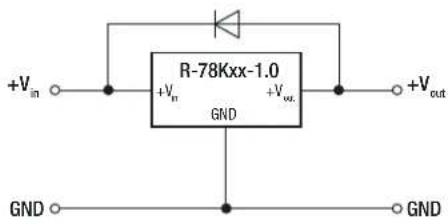
Optional Diode Protection Circuit
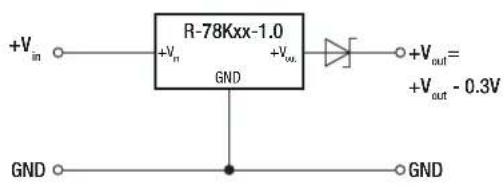
Add a blocking diode to Vout if current can flow backwards into the output, as this can damage the converter when it is powered down.
The diode can either be fitted across the device if the source is low impedance or fitted in series with the output (recommended).
Optional Protection 1:
Optional Protection 2:
ENVIRONMENTAL
| Parameter | Condition | Value | |
| Operating Temperature Range | refer to “Derating Graph” | -40°C to +90°C | |
| Maximum Case Temperature | +110°C | ||
| Temperature Coefficient | 0.01%/K | ||
| Operating Humidity | non-condensing | 95% RH max. | |
| MTBF | according to MIL-HDBK-217F, G.B., +25°C | R-78K1.8-1.0 | 5139 x 10^3 hours |
| R-78K2.5-1.0 | 4990 x 10^3 hours | ||
| R-78K3.3-1.0 | 4878 x 10^3 hours | ||
| R-78K5.0-1.0 | 5031 x 10^3 hours | ||
| R-78K9.0-1.0 | 4546 x 10^3 hours | ||
| R-78K12-1.0 | 4340 x 10^3 hours | ||
| R-78K15-1.0 | 4546 x 10^3 hours | ||
| Vibration | 10-55Hz, 2G, 30min along X,Y and Z axis | ||
| continued on next page | |||
Specifications (measured @ Ta= -40°C to +90°C, V _th = 24VDC, full load and after warm-up unless otherwise stated)
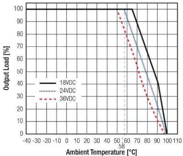
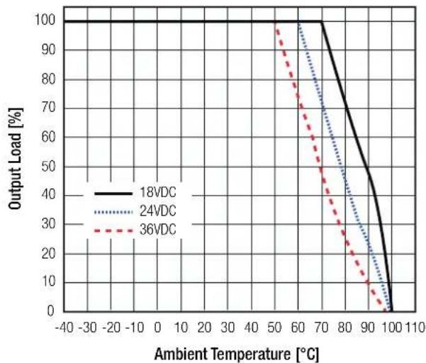
Derating Graph
(@ Chamber and natural convection 0.1m/s, over Vin)
R-78K1.8-1.0 & R-78K2.5-1.0
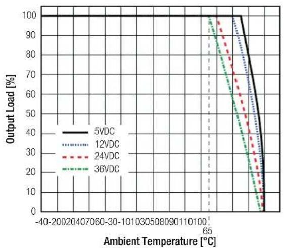
R-78K3.3-1.0
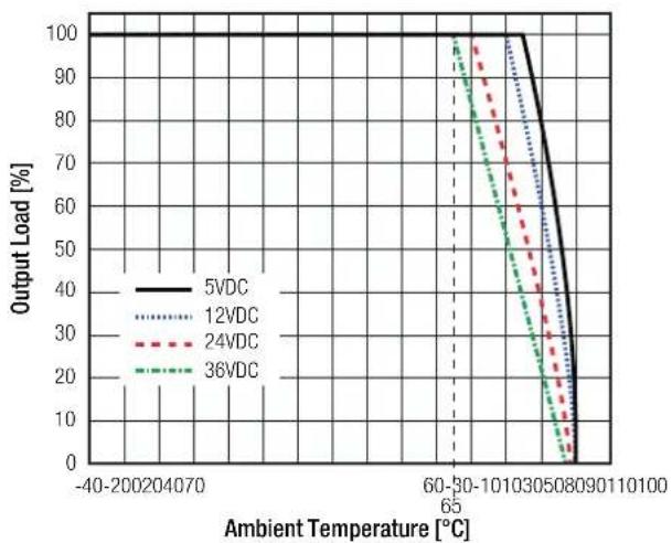
line
| Ambient Temperature [°C] | 5VDC | 12VDC | 24VDC | 36VDC | | ------------------------ | ---- | ----- | ----- | ----- | | -40-200204070 | 100 | 100 | 100 | 100 | | 65 | 100 | 100 | 100 | 100 | | 60-30-10103050890110100 | 100 | 100 | 100 | 100 |R-78K5.0-1.0
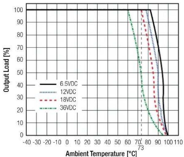
line
| Ambient Temperature [°C] | 6.5VDC | 12VDC | 18VDC | 36VDC | | ------------------------ | ------ | ----- | ----- | ----- | | -40 | 100 | 100 | 100 | 100 | | -30 | 100 | 100 | 100 | 100 | | -20 | 100 | 100 | 100 | 100 | | -10 | 100 | 100 | 100 | 100 | | 0 | 100 | 100 | 100 | 100 | | 10 | 100 | 100 | 100 | 100 | | 20 | 100 | 100 | 100 | 100 | | 30 | 100 | 100 | 100 | 100 | | 40 | 100 | 100 | 100 | 100 | | 50 | 100 | 100 | 100 | 100 | | 60 | 100 | 100 | 100 | 100 | | 73 | 100 | 100 | 100 | 100 | | 80 | 95 | 95 | 95 | 95 | | 90 | 75 | 75 | 75 | 75 | | 100 | 5 | 5 | 5 | 5 | | 110 | 0 | 0 | 0 | 0 |R-78K9.0-1.0
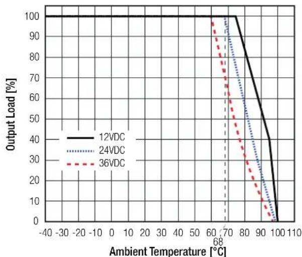
R-78K12-1.0
line
| Ambient Temperature [°C] | 18VDC | 24VDC | 36VDC | | ------------------------- | ----- | ----- | ----- | | -40 | 100 | 100 | 100 | | -30 | 100 | 100 | 100 | | -20 | 100 | 100 | 100 | | -10 | 100 | 100 | 100 | | 0 | 100 | 100 | 100 | | 10 | 100 | 100 | 100 | | 20 | 100 | 100 | 100 | | 30 | 100 | 100 | 100 | | 40 | 100 | 100 | 100 | | 58 | 100 | 100 | 100 | | 67 | 95 | 95 | 95 | | 76 | 85 | 85 | 85 | | 85 | 75 | 75 | 75 | | 93 | 65 | 65 | 65 | | 101 | 55 | 55 | 55 | | 110 | 45 | 45 | 45 | | 128 | 35 | 35 | 35 | | 146 | 25 | 25 | 25 | | 164 | 15 | 15 | 15 | | 182 | 5 | 5 | 5 | | 200 | 0 | 0 | 0 |R-78K15-1.0
Specifications (measured @ Ta= -40°C to +90°C, V_th=24VDC , full load and after warm-up unless otherwise stated)
SAFETY AND CERTIFICATIONS
| Certificate Type (Safety) Report Number Standard | ||
| Audio/Video, information and communication technology equipment - Part 1: Safety requirements (CB Scheme) | 085-210593601-100 | IEC62368-1:2018 3rd Edition |
| Audio/Video, information and communication technology equipment - Part 1: Safety requirements | EN IEC 62368-1:2020+A11:2020 | |
| RoHS2 RoHS 2011/65/EU + AM2015/863 |
| EMC Compliance Condition Standard / Criterion | ||
| Electromagnetic compatibility of multimedia equipment - Emission requirements with external filter EN55032, Class B |
EMC filtering suggestions according to EN55032
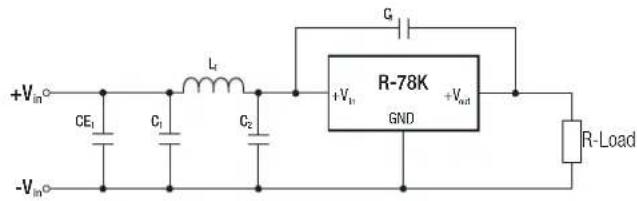
| Component List Class B for 1.8V, 2.5V & 3.3V version | |||
| C1/C2 | L1 | C3 | CE1 |
| 10μF | 22μH | 1nF | 100μF |
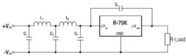
| Component List Class B for 15V & 15V version | ||||
| C1/C2 | L1 | C3 | C4 | L2 |
| 10μF | 22μH | 1nF | 1nF | 3.9μH |
DIMENSION AND PHYSICAL CHARACTERISTICS
| Parameter Type Value | ||
| Material | case | black plastic, (UL94 V-0) |
| potting | PU, (UL94 V-0) | |
| PCB | FR4, (UL94 V-0) | |
| Dimension (LxWxH) 11.5 x 7.55 x 10.2mm | ||
| Weight 1.7g typ. |
Dimension Drawing (mm)
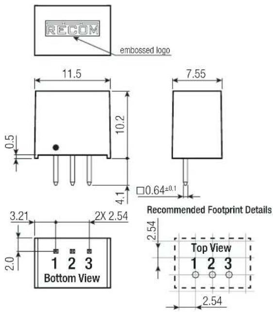
Pinning Information
| Pin # | Single |
| 1 | +V_IN |
| 2 | GND |
| 3 | +V_OUT |
Tolerance:
$$ x x. x = \pm 0. 5 m m $$
$$ x x. x x = \pm 0. 2 5 \mathrm{mm} $$
Specifications (measured @ Ta= -40°C to +90°C, V_in = 24VDC, full load and after warm-up unless otherwise stated)
| PACKAGING INFORMATION | ||
| Parameter Type Value | ||
| Packaging Dimension (LxWxH) tube 520.0 x 9.2 x 19.0mm | ||
| Packaging Quantity 43pcs | ||
| Storage Temperature Range -50°C to +125°C | ||
| Storage Humidity non-condensing 95% RH max. | ||