L-550AX - Modtager LUXMAN - Gratis brugsanvisning og manual
Find enhedens vejledning gratis L-550AX LUXMAN i PDF-format.

Brugerspørgsmål om L-550AX LUXMAN
0 spørgsmål om dette apparat. Besvar dem du kender, eller stil dit eget.
Stil et nyt spørgsmål om dette apparat
Download vejledningen til din Modtager i PDF-format gratis! Find din vejledning L-550AX - LUXMAN og tag din elektroniske enhed tilbage i hånden. På denne side er alle dokumenter nødvendige for brugen af din enhed offentliggjort. L-550AX af mærket LUXMAN.
BRUGSANVISNING L-550AX LUXMAN

INTEGRATED AMPLIFIER
L-550AX
Contents
Precautions 1
Features of This Unit 2
Names and Functions 4
Connections 12
Operations.... 16
How to Use Remote Control.... 18
Block Diagram 20
Specifications 21
Before Asking for Repair Services 22
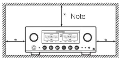
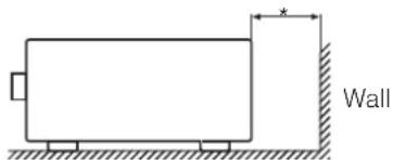
Installation place
This·unit·shall·be·installed·in·a·well-ventilated·and·effectively·heat-released·place·because·this·unit·is·an·A-class·amplifier-and-generates·considerable·heat.
Especially, installation of this unit where direct sunlight is present, where the temperature rises excessively high such as close to a heater, or where it is humid or dusty may cause a malfunction even if heat is efficiently released. Therefore, do not install this unit in such places.
Ventilation holes
The·ventilation·holes·on·the·top·and·bottom·boards·of·this·product·must·not·be·blocked·because·this·unit·is·an·A-class·amplifier·and·generates·considerable·heat.·If·the·amplifier·is·installed·on·a·rack·or·the·like,·secure·ample·space·for·cooling·and·leave·the·door·open.·Do·not·pile·up·other·things·on·the·amplifier·and·never·put·articles·on·it.·Failure·to·observe·this·may·cause·a·malfunction.
Note:
For·heat·dispersal,·do·not·install·this·equipment·in·a·confined-space·such·as·a·book·case·or·similar·unit.
Precautions in connecting with other components
When·connecting·this·unit·to·input·devices·such·as·a·CD·player,·an·SACD·player,·a·tuner,·and·a·recorder,·be·sure·to·turn·off·the·power·of·this·unit·and·all·other·connected·devices. Failure·to·observe·this·may·generate·a·strong·noise·resulting·in·speaker·damage·or·cause·a·malfunction.
The pin - plug to be inserted in each input terminal of this unit shall be pushed in firmly. If the grounding terminal is inadequately connected, noises including hum may be generated, resulting in an adverse S/N ratio.
Cautions in connecting speakers
When-making-speaker-system-connections,exercise-extra-care-not-to-short-circuit-between⊕and⊖of-the-speaker-terminals-and-speaker-input-terminals-of-this-unit.If-a-large-signal-is-applied-to-the-amplifier-with-its-circuit-left-short-circuited,a-large-current-may-be-passed-through-the-output-circuit-and-cause-a-malfunction.
The sound is not generated shortly after the power supply is turned on.
This-amplifier-is-equipped-with-a-time-muting-circuit-in-order-to-separate-the-output-circuit.--Therefore,-no-sound-is-generated-shortly-after-the-power-supply-is-turned-on.
If the volume-control is moved to a high sound level before the time-muting circuit is canceled, a large sound is suddenly generated. Please be advised that the volume-control shall be set to a low level at first and adjusted after sound comes out of the speakers.
Protection circuit
This·product·is·equipped·with·a·protection·circuit·that·is·activated·upon·detection·of·overcurrent,·abnormally·high·temperature,·and·DC·drift·to·protect·the·amplifier·and·speakers. When·the·protection·circuit·is·activated,·the·output·to·the-speaker·terminal·is·shut-off·and·the·standby-indicator·blinks·to·show·that·this·unit·is·in·the·muting·state. If·the·protection·circuit·is·frequently·activated·even·when·disconnecting·the·power·plug·from·the·wall-outlet-and·turning-on-the-power-again·after·a·lapse-of-a·certain·time,·please·consult·your-dealer.
Batteries
Caution:
Batteries·used·for·remote·controller·shall·not·be·exposed·to·excessive·heat·such·as·sunshine,·fire·or·the·like.
Repair and adjustment
When-repairs-or-adjustments-are-needed,please-ask-the-dealer-where-you-bought-the-unit.
Cleaning
For·cleaning,·use·a·piece·of·soft·cloth·to·wipe·the·unit·such·as·cleaning·cloth·available·on·the·market.·If·the·unit·has·become·very·dirty,·remove·the·dirt·with·soft·cloth·absorbing·a·small·amount·of·neutral·detergent,·and·then·wipe·the·unit·with·dry·cloth.·Do·not·use·a·solvent·like·benzine·or·thinner·because·such·a·substance·can·often·damage·the·exterior.
LECUA-WM - LUXMAN Electric Controlled Ultimate Attenuator - Waiting Matrix
Application-of-the-system-to-obtain-attenuation-by-combining-2-fixed-resistances-connected-to-this-product-series-has-improved-efficiency-of-the-LECUA1000-attenuator-used-in-our-flagship-model, C-1000f.
The-shortest-signaling-route-has-been-achieved-by-the-integrated-amplifier-circuit-thanks-to-the-3D-structure-of-the-mounting-boards.-
Controlling·LECUA-WM·to·the·level·equal·to·the·volume·position·detected·by·a·microprocessor·has·achieved·the·operation·feeling·similar·to·our·conventional·sliding-type·volume·controls.
ODNF - Only Distortion Negative Feedback -
The-amplification-feedback-circuit-that-has-acquired-the-high-speed-primary-slew-rate-and-ultra-high-bandwidth-by-feeding-back-only-distortion-components-generated-during-amplification-to-maintain-the-pure-sound-quality-of-the-main-amplifier-that-is-almost-non-feedback.
The-newest-version, 3.0A, has achieved the low impedance and high S/N ratio of the transmission circuit by parallelization of the first and second stages of the amplifier circuit. In addition, the input stages of the error detection circuit are parallelized to moderate the frequency characteristic and noise.
2 parallel push-pull output stages
2·parallel·push-pull·structure·of·bipolar·transistor. Pure·class·A·rated·output·20W+20W·(8Ω).
High-inertia power supply
High-inertia·electronic·circuit·that·combines·a·large-capacity·El-core-type-power-transformer-with-customizable·10,000μF·x·4·capacitor·blocks.
Parallel speaker relays
This·unit·is·equipped·with·large·type·of·2·parallel·speaker·relays·with·a·low·resistance·value·to·reduce·the·impedance·of·the·speaker·output·lines.
Beeline construction
Newly-designed-beeline-construction-composes-the-audio-input-signal-via-the-optimally-shortest-route-to-the-speaker-output.
Selector switch IC
Selector-switch-IC-with-high-sound-quality,which-is-used-in-the-top-end-control-amplifier,C-1000f,improves-the-separation-and-crosstalk-performances.
Schottky barrier diode
Application-of-schottky-barrier-diode-manufactured-by-Nihon-Inter-Electronics-Corporation-that-has-less-switching-noises-and-higher-conversion-efficiency-to-the-DC-voltage-for-the-power-supply-rectifier-circuit.
LUXMAN's original OFC wires
Our original OFC-wires are used in the internal wiring to achieve smooth signal transmission thanks to the spiral wrap shielding on each core and the non-plating process on the core wire.
Round pattern board
After careful consideration of delicate audio signal flow, a round pattern board has been applied to achieve smooth signal transmission.
Phono amplifier
This·unit·is·equipped·with·a·phono·amplifier·that·is·compatible·with·the·MM/MC·cartridge·to·achieve·analog·record·reproduction·in·a·high-grade·level·without·adding·a·dedicated·phono·amplifier.
Separate function
This·unit·is·equipped·with·a·separate·switch·to·separate·the·pre-amplifier·and·power-amplifier·each·other·that·enables·the·bi-amp·connection·adding·a-power-amplifier·and·the·coexistence·with·an·AV·system.
Loopless chassis structure
This·unit·consists·of·the·independent·construction·of·a·loopless·chassis·to·eliminate·increased·ground·impedance·caused·by·chassis·current.
18 mm pitch RCA terminal
Introduction-of-18-mm-pitch-all-RCA-input/output-terminals allows-even-a-high-performance-line-cable-with-large-plug-to-be-connected.
Large type of speaker terminals
Speaker terminals·(A·and·B·systems)·of·inline·layout·(with-same characteristics·for-right-and-left),·which·is-compatible-with·Y·lugs-and-banana-plugs-to-enable·easy·connection-with-extra-thick-speaker-cables.
New standard size
This·unit·has·been·manufactured·based·on·LUXMAN's·new-standard-size·(440mm·wide,·common·with·a·series·of·separate·amplifiers·and·a·series·of·SACD·players.
Headphone output terminal
This-terminal allows you to casually enjoy sound even at midnight.
AC inlet
This·inlet·enables·the·connection·with·an·external·power·cable.
Needle-type meter
This·unit·is·equipped·with·needle-type·meters·lighted·with·LED,·which·improves·the·visibility·in·the·room·where·the·unit·will·be·installed.
Remote control encased in aluminum
The high-grade remote-control, which is encased in aluminum, can control applicable CD/SACD-players.
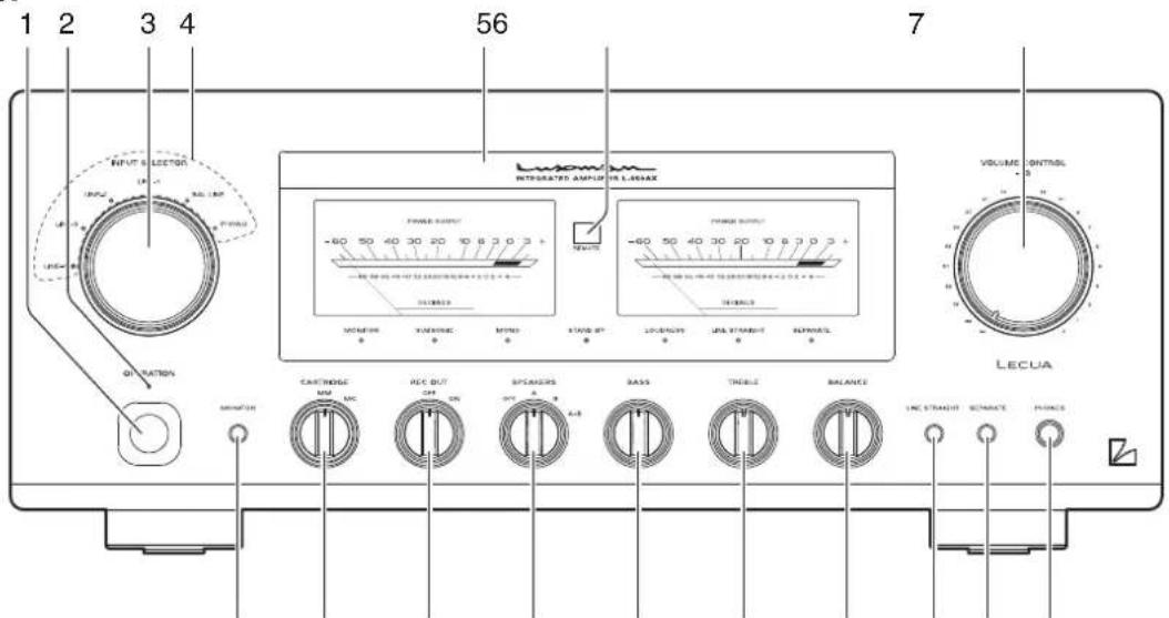
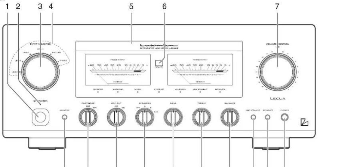
Names and Functions
Front panel
891011121314151617
1. Operation switch (OPERATION)
Toggles·the·power·on·and·off.
When·wiring·or·connection·is·performed,·be·sure·to·turn·off·this·switch.
2. Operation indicator (OPERATION)
Blinks-in-the-time-of-muting-mode-when-the-operation-switch-is-turned-on-and-lights-up-when-the-operation-state-is-activated-afterward.-This-indicator-blinks-when-the-unit-is-in-the-muting-mode-or-when-the-volume-is-adjusted-with-the-remote-control.-
3. Input selector (INPUT SELECTOR)
Selects·an·input·device·from·the·devices·such·as·a·CD·player·,an·SACD·player·and·a·tuner·connected·to·each·input·terminal.
The-input-selector-has-6-positions-consisting-of-LINE-4, LINE-3, LINE-2, LINE-1, BAL-LINE, and PHONO-from-left-to-right-that-correspond-to-each-input-terminal-on-the-rear-panel. The-knob-is-rotated-to-light-the-input-indicator-of-the-input-device-to-be-selected.
4. Input indicator
Lights-up-at-the-input-device-to-be-selected-with-the-input-selector-or-remote-control.
5. Display
Displays·the·operation·status·of·this·unit.
This·display·is·composed·of·7·indicators·and·2·power·meters.
6. Remote control infrared receiver (REMOTE)
This is a sensor to receive signals from the accessory remote control.
7. Volume control (VOLUME CONTROL)
Adjusts·the·sound·volume.·Sound·is·not·generated·when·this·control·is·rotated·counterclockwise·to·the·end,·and·then,·the·sound·volume·gradually·becomes·higher·when·the·control·is·slowly·rotated·clockwise.
8. Headphone jack (PHONES)
Insert·the·headphone·plug·into·this·output·jack.·Even·when·the·plug·is·inserted,·signals·to·the·speaker·output·terminal·are·not·interrupted.·Accordingly,·to·listen·to·sound·with·only·use·of·headphones,·set·the·speaker·selector·to·off.
9. Separate switch (SEPARATE)
Separates·the·pre-amplifier·and·main-amplifier·each·other.
off:…Uses·this·unit·as·a·normal·pre-main·amplifier.
(separate...
indicator-off)
on: Feeds external signals from the MAIN IN termi-
(separate-indicator-on) nal·on·the·rear·panel·to·the·main-amplifier·section.
- Every-pressing-of-this-switch-toggles-the-separate-on-and-off.
The·separate·indicator·lights·up·when·the·separate·switch·is·on.
When the separate switch is set to on, the volume control of this unit cannot adjust the volume of the speakers connected to this unit. Volume adjustment shall be performed at the input device side such as the control amplifier connected to the MAIN IN terminal.
Entry of direct output into the MAIN IN terminal from a CD player or other devices that cannot adjust sound volume constantly provides a full power state and accordingly results in the risk of speaker damage.
For such input devices, be sure to use a control amplifier equipped with the sound volume adjustment function as a relay, generate sound through the speakers with volume lowered, and adjust the volume to your favorite level.
When arranging the wiring, be sure to turn off the power of this unit.
Front panel
8910111213741516
10. Line straight switch (LINE STRAIGHT)
Enhances·the·purity·of·the·sound·quality·by·bypassing·the·balance·control·circuit,·tone·control·circuit,·or·the·like.
off···Line·straight·off/bypass·off (line·straight· indicator·off)
on:…Line·straight·on/bypass·on (line·straight· indicator·on)
- Every-pressing-of-this-switch-toggles-the-line-straight-on-and-off.
The-line-straight-indicator-lights-up-when-the-line-straight-switch-is-on.
When the line straight switch is set to on, the balance control, tone control, subsonic, monaural and loudness cannot be adjusted and the mode selector does not function.
11. Balance control (BALANCE)
Adjusts·the·balance·of·sound·volume·between·right·and·left·channels.
Rotating·this·switch·counterclockwise·causes·the·left·sound·volume·to·be·enhanced, and·rotating·the·switch·clockwise·causes·the·right·sound·volume·to·be·enhanced.
This-switch shall be set to the center position under normal conditions, and rotated to make adjustment if necessary.
When the line straight switch is set to on, this switch does not function.
12. Tone control for treble (TREBLE)
Controls-the-frequency-characteristics-in-the-high-frequency-range.
When this switch is set to the center position, flat frequency characteristic is obtained. Rotating the switch clockwise causes the high-frequency range to be enhanced, and rotating the switch counterclockwise causes the high-frequency range to be attenuated.
When the line straight switch is set to on, this switch does not function.
13. Tone control for bass (BASS)
Controls·the·frequency·characteristics·in·the·low-frequency·range.
When this switch is set to the center position, flat frequency characteristic is obtained. Rotating the switch clockwise causes the low-frequency range to be enhanced, and rotating the switch counterclockwise causes the low-frequency range to be attenuated.
When the line straight switch is set to on, this switch does not function.
14. Speaker selector (SPEAKERS)
Selects·either·of·2·speaker·systems,·A·or·B,·located·at·the rear·panel.
OFF:·Activates·only·headphones.·No·sound·is·generated·from·any·speakers.
A:·Selects·the·A·system·speaker·terminal.·(center)
B:·Selects·the·B·system·speaker·terminal.
A+B:·Simultaneously-activates-both-A-and-B-system-speakers. When both-speaker-terminals are simultaneously-used, select-speakers with impedance-of-8-ohms-or-more-because-both-output-terminals are connected-in-parallel.
15. Recording switch (REC OUT)
Sends-recording-signals-to-the-recorder-connected-to-this-unit.
OFF:…Does not send recording signals to the recorder output terminals on the rear panel.
- When not using the recorder, set the recording switch to this position.
ON:·Selects·an-input·source·to·be·recorded·with·the·input·selector·and·sends·recording·signals·to·the-recorder-connected·the-recorder·output·terminals-of·this·unit.
16. Cartridge selector (CARTRIDGE)
Changes·the·gain·level·of·the·equalizer·amplifier·(amplifier·circuit·required·to·play·an·analog·record).
MC:·Selects·an·MC·(moving·coil)·type·cartridge·of·low-output·voltage.
- Be-aware-that-the-sound-volume-becomes-higher-and-unbalanced-sound-without-high-frequencies-is-generated-owing-to-the-impedance-when-"MC"-is-selected-during-use-of-the-MM-type-cartridge.
MM:· Selects·an·MM·(moving·magnet)·type·cartridge·of·high·output·voltage.
17. Monitor switch (MONITOR)
Toggles·between·use·and·nonuse·of·the·monitor·input·terminals·(MONITOR)·on·the·rear·panel.
on:: Enables-to-reproduce-the-data-from-the-recorder. (monitor-- indicator-off)
off:· ·Enables·to·reproduce·the·data·from·the·source· (monitor· indicator·on) selected·with·the·input·selector.
- Every-pressing-of-this-switch-toggles-the-monitor-on-and-off.
The·monitor·indicator·lights·up·when·the·monitor·switch·is·on.
Names and Functions
Display
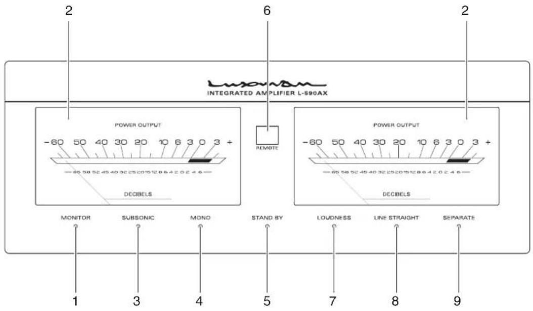
1. Monitor indicator (MONITOR)
Lights-up-when-the-monitor-switch-is-on.
2. Power meters
The left-meter reads the output of the L-channel, and the right-meter reads the output of the R-channel. The meters read the level in decibels.
The·meters·light·when·the·power·is·on.
3. Subsonic indicator (SUBSONIC)
Lights-up-when-the-subsonic-switch-is-on.
4. Monaural indicator (MONO)
Lights-up-when-the-monaural-switch-is-on.
The subsonic, monaural and loudness can be toggled only from the accessory remote control (RA-17).
5. Standby indicator (STAND BY)
Lights-up when the AC plug is plugged into a wall socket and the operation switch is set to off.
This-indicator-turns-off-when-the-AC-plug-is-disconnected-from-the-wall-socket-or-the-power-switch-is-set-to-on.-This-indicator-blinks-when-the-protection-circuit-is-activated.-
6. Remote sensor (REMOTE)
Receives·signals·from·the·accessory·remote·control.
7. Loudness indicator (LOUDNESS)
Lights-up-when-the-loudness-switch-is-on.
8. Line straight indicator (LINE STRAIGHT)
Lights-up-when-the-line-straight-switch-is-on.
When the line straight switch is set to on, the subsonic, monaural and loudness cannot be adjusted from the accessory remote control.
When one of these switches is pressed, the line straight indicator blinks for 3 seconds to show that this unit cannot be operated.
Adjust the subsonic, monaural or loudness after setting the line straight switch to off.
9. Separate indicator (SEPARATE)
Lights-up-when-the-separate-switch-is-on.
The subsonic, monaural and loudness can be toggled only from the accessory remote control (RA-17).
Names and Functions
Rear panel
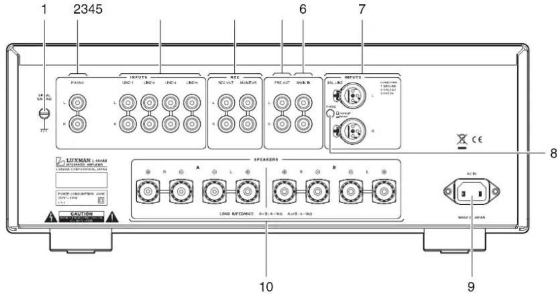
1. Signal ground (ground terminal) (SIGNAL GROUND)
Is-a-ground-terminal-for-devices-to-be-connected-to-this-unit. This-terminal-is-used-to-reduce-noise-when-other-devices-are-connected. This-terminal-is-designed-not-for-safety.
2. Phono input terminal (PHONO)
Is·an·input·terminal·to·connect·an·analog·record·player.
Do not connect a CD player or other devices whose output level is high.
Normal playback cannot be achieved due to sound crack.
3. LINE-1, LINE-2, LINE-3, and LINE-4 input terminals (unbalance) (LINE-1, LINE-2, LINE-3, LINE-4)
Are-used-for-high-level-signal-inputs-from-a-CD-player,an-SACD-player,a-tuner,a-DVD-player,a-TV,and-other-such-devices.The-input-sensitivity-is-180-mV,and-the-impedance-is-42-kohms.These-input-terminals-offer-the-same-functions.
4. Recorder input/output terminals (REC)
Connect-the-audio-input/output-of-a-recorder.-The-audio-input-of-a-recorder-is-connected-to-REC-OUT,-and-the-audio-output-of-a-recorder-is-connected-to-MONITOR.-
Do not insert shortpin plugs into REC OUT. No sound is generated.
5. Pre-out terminal (PRE OUT)
This terminal is used to obtain the output of the preamplifier. A bi-amp connection can be performed with a combination of an external power amplifier because this terminal always provides output regardless of the separate switch setting.
Do not insert shortpin plugs into PRE OUT. No sound is generated.
6. Main in terminal (MAIN IN)
Provides·input·to·the·main-amplifier·section·when·the·pre-amplifier·and·main-amplifier·are·separated·by·setting·the·separate·switch·to·on.
7. Balance input terminals (BAL LINE)
Are the balance type input terminals of the LINE level for an XLR connector (Cannon connector).
8. Phase inverters (PHASE)
Change·the·phase·when·the·balance·input·terminal·is·used. The·phase·shall·be·corresponding·to·the·phase·of·the·input·device.
Normal-position①·GROUND
②·COLD
③HOT
□·Invert·position·①·GROUND
·②·HOT
③·COLD
9. AC inlet (AC IN)
Connects·the·accessory·power·cable.·The·power·shall·be-supplied·from·a-household·wall·socket.
10. Speaker terminals (SPEAKERS)
Connects·a·speaker·system.
The-right-speaker-terminal shall-be-connected-to-the-R-side, and-the-left-speaker-terminal shall-be-connected-to-the-L-side-in-consideration-of-the-polarity.
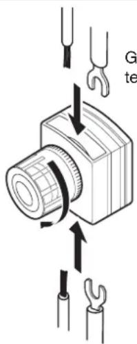
General type terminal
* It is possible to insert cables from below as well as from above.
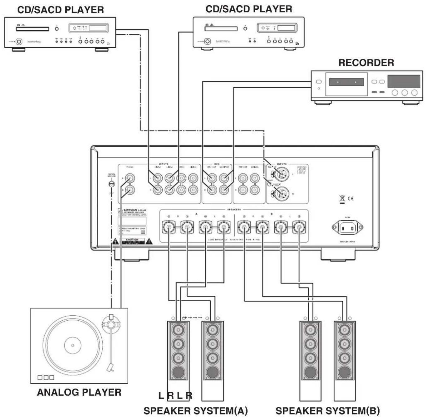
Connections

flowchart
graph TD
    A["ANALOG PLAYER"] --> B["CD/SACD PLAYER"]
    B --> C["CD/SACD PLAYER"]
    C --> D["RECORDER"]
    D --> E["SPEAKER SYSTEM(A)"]
    D --> F["SPEAKER SYSTEM(B)"]
How to connect power supply
Use the accessory-power-cable-and-insert-the-AC-plug-in-an-outlet-on-the-wall-in-the-room-where-the-unit-will-be-installed.
How to connect CD player, SACD player, tuner, or other devices
Connect-between-the-output-terminals-of-a-CD-player,an-SACD-player,a-tuner,or-other-such-input-devices-and-the-LINE-1-input-terminals-of-this-unit-with-2-(R-and-L)pin-plug-cables-or-balanced-cables.
For·LINE-2,·LINE-3,·and·LINE-4·input·terminals,·connection-in·the·same·fashion-as·the·LINE-1·terminals·provides·the-reproduction·likewise.
How to connect speakers
Connect-the-left-channel-speaker-to-the-LEFT-SPEAKER-terminal-of-this-unit-and-the-right-channel-speaker-to-the-RIGHT-SPEAKER-terminal.
Securely connect the terminal of the speaker system to the speaker terminal (red) of this unit, and the terminal of the speaker system to the speaker terminal (black) of this unit.
If the ⊕ and ⊖ terminals are reversely connected to either of the right and left speaker systems, the acoustic phases of the sound reproduced from the right and left speaker systems are also reversed. In such a case, be aware that the sound level in the low range will be reduced and the acoustic stability will worsen, thus failing in normal stereo playback.
Connections
flowchart
graph TD
    A["ANALOG PLAYER"] --> B["CD/SACD PLAYER"]
    B --> C["CD/SACD PLAYER"]
    C --> D["RECORDER"]
    D --> E["SPEAKER SYSTEM(A)"]
    D --> F["SPEAKER SYSTEM(B)"]
How to connect record player
Connect·between·the·output·terminal·of·an·analog·record·player·and·the·PHONO·terminal·of·this·unit·with·2·(R·and·L)·pin-plug·cables.
For some types of players, the ground wire from the phonomotor or the tone-arm should be connected to the ground-terminal of this unit.
The·phono-equalizer·of·this·unit·uses·the·MM·or·MC·cartridge.·If·an·MC·cartridge·with·low·output·voltage·is·used,·set·the·cartridge·selector·on·the·front·panel·to·the·MC·position.
The output from a record player equipped with a phono equalizer or from an independent phono equalizer shall be connected to the line input terminals of this unit.
How to connect recorder
1. Connection to monitor terminal (playing)
Connect-between-the-line-output-terminals-(LINE-OUT)of-a-recorder-and-the-monitor-terminals-of-this-unit-with-pin-plug-cables-in-consideration-of-R-and-L.-Now, -setting-the-monitor-switch-on-the-front-panel-or-the-remote-control-to-on-provides-playback.
2. Connection to REC OUT terminal (recording)
When the sound source from the various input devices is reproduced, which are connected to the PHONO or LINE terminals of this unit, setting the recording switch to on allows users to provide the REC OUT terminal with the signal. Connection between the REC OUT terminal of this unit and the line input terminals (LINE IN) of the recorder with pin plug cables is required for recording on the recorder. After the connection, you can enjoy listening to the sound from the speaker system and record the sound at the same time. These output signals for recording are not affected by the control functions such as the volume control and tone control functions.
When you need not toggle an input source to be recorded (especially when a recorder connected to the recorder output terminals is recording), do not operate this switch. Do not insert shortpin plugs into REC OUT. No sound is generated.
When a CD recorder, tape recorder, or other devices are connected, be aware that the playback sound volume becomes low or no sound is generated if the device extremely decreases the impedance of the line input terminals of the recorder or causes short-circuit on the line input terminals or if the recording switch is set to on.
How to connect PRE OUT/MAIN IN terminal
Either the pre-amplifier or main-amplifier can be separately used.
When the pre-amplifier or main-amplifier is separately used, set the separate switch on the front panel to on.
When-only-the-pre-amplifier-is-used,connect-the-PRE-OUT-terminal-of-this-unit-to-the-input-terminal-of-another-power-amplifier,and-when-only-the-main-amplifier-is-used,connect-the-MAIN-IN-terminal-of-this-unit-to-the-output-terminal-of-another-power-amplifier.
When this amplifier is used without separating between pre-amplifier and main-amplifier, set the separate switch on the front panel to off, or no sound is generated.
Do not insert shortpin plugs into PRE OUT. No sound is generated.
Before operation
- · Ensure · that · the · connections · are · correctly · performed · (Normal · playback · cannot · be · achieved · with · wrong · connection · of · R, · L, · ⊕, · or · ⊖)
- When the power is toggled between on and off or the input selector is changed over, set the volume control to the minimum position in advance.
Playback procedure
- Press·the·operation·switch·after·ensuring·that·the·volume-control·is·set·to·the·minimum·position.
- Select·a-source-to-be-reproduced-with-the-input-selector.
- Adjust the sound level with the volume control.
4.…Operate·the·line·straight·switch,·balance·control,·and·tone·control·according·to·the·reproduced·source.
How to operate line straight switch
The-line-straight-switch-is-used-to-play-sound-with-the-shortest-signaling-route-for-enhancing-the-purity-of-the-source-selected-with-the-input-selector.-When-this-switch-is-set-to-on,-the-balance-control,-tone-control,-subsonic,-monaural-and-loudness-are-bypassed.
How to operate balance control
The balance-control allows users to adjust the balance of sound volume between right and left channels.
When the balance adjustment is not required, the balance control is set to the center position.
When the line straight switch is set to on, the balance control does not function.
How to operate the tone control
This·unit·has·the·tone·control·function·for·the·low-frequency·and·high-frequency·ranges.
The low-frequency-range-type-works-in-the-300-Hz-or-lower. The tone-control-is-set-to-flat-frequency-characteristic-at-the-center-position. Rotating-the-control-clockwise-causes-the-low-frequency-range-to-be-enhanced, and rotating-the-control-counterclockwise-causes-the-low-frequency-range-to-be-attenuated.
The·high-frequency·range·type·works·in·the·3·kHz·or·higher. As·with·the·low-frequency·range·type, the·tone·control·is·set·to·flat-frequency·characteristic·at·the·center·position. Rotating·the·control·clockwise·causes·the·high-frequency·range·to·be-enhanced, and·rotating·the·control·counterclockwise·causes·the·high-frequency·range·to·be·attenuated.
For both the low-frequency and high-frequency ranges, the right and left channels interlockingly function.
When the line straight switch is set to on, the tone control does not function.
How to record a source
- Select·a-source·to·be-recorded·with·the-input-selector.
- Set the recording switch to on.
- Play the source to be recorded and set the recorder to the recording state.
*·Operation·of·the·tone·control·or·balance·control·does·not·affect·the·recording·signals.
*…The-recording-switch-works-when-the-power-is-on.
Procedure of timer-controlled recording
- ·Turn·on·the·operation·switch·to·activate·this·unit.
- Select·a·source·to·be·recorded·under·timer·control·with·the·input·selector.
- Set the recording switch to on.
- Perform·time·setting·for·start·and·stop·times·with·your·timer.
- Refer to the operating instructions of the timer and other connected devices for further information.
If the volume control is not set to low levels, the source selected with the input selector may be reproduced from the speakers. Be sure to set the volume control to a low level. When timer-controlled recording is performed, operations of the amplifier are the same as regular use.
Procedure of timer-controlled playing
- ·Turn·on·the·operation·switch·to·activate·this·unit.
- Select-a-source-to-be-reproduced-under-timer-control-with-the-input-selector.
3.·Adjust·the·volume·level·with·the·volume·control. - Perform·time·setting·for·start·and·stop·times·with·your·timer.
- Refer to the operating instructions of the timer and other connected devices for further information.
Memory
This·unit·stores·the·following·items·when·the·power·is·off:
| ItemTo-be-stored |
| INPUTSelected-source |
| METERon/off |
| MONITORon/off |
| SUBSONICon/off |
| MONOon/off |
| LOUDNESSon/off |
| LINE-STRAIGHTon/off |
| SEPARATEon/off |
Memory reset
The following operations restore all the settings to the factory defaults.
(1)·Turn-off-the-power-of-this-unit.
(2)·Hold·down·the·operation·switch·on·the·main·unit·for·5·seconds·or·more·and·press·the·line·straight·switch·on·the·main·unit·once, and the power state switches from on to off.
That's-all-for-memory-reset.
| Factory-default |
| ItemDefault |
| INPUTLINE-1 |
| METERon |
| MONITORoff |
| SUBSONICoff |
| MONOoff |
| LOUDNESSoff |
| LINE·STRAIGHToff |
| SEPARATEoff |
Remote control (RA-17)
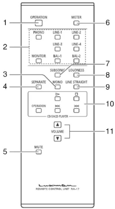
1. Operation switch (OPERATION)
Toggles·the·power·on·and·off.
When·wiring·or·connection·is·performed,·be·sure·to·turn·off·this·switch.
2. Input selector
(LINE-1, LINE-2, LINE-3, LINE-4, BAL-1, BAL-2, PHONO, MONITOR)
Selects·an-input-terminal-from-among-the-unbalanced-input terminals-on-the-rear-panel-consisting-of-LINE-1, LINE-2, LINE-3, LINE-4, PHONO, and MONITOR-or-the-balanced-input-terminal-consisting-of-BAL-LINE.
*The·balanced·input·terminal·(BAL·LINE)·can·be-selected·by·pressing·either·of·BAL-1·or·BAL-2.
3. Monaural switch (MONO)
Mixes·the·signals·from·right·and·left·channels.·The·monaural-indicator·lights·up·when·this·switch·is·pressed.
Pressing·this·button·again·to·turn·off·the·monaural·switch·allows·regular·stereophonic·reproduction.
*…When·the·line·straight·switch·is·set·to·on,·this·switch·does·not-function.
4. Separate switch (SEPARATE)
Separates·the·pre-amplifier·and·main-amplifier·each·other.
off:…Uses·this·unit·as·a·normal·pre-main·amplifier.·(separate)
indicator-off)
on: Feeds·external·signals·from·the·MAIN·IN·termi- (separate)
indicator-on) nal-on-the-rear-panel-to-the-main-amplifier-sec-tion.
- Holding·down·this·switch·for·1·second·toggles·the·separate·switch·on·and·off.
- The·separate·indicator·lights·up·when·the·separate·switch·is·on.
5. Mute switch (MUTE)
Activates·the·mute·function·and·blinks·the·power-on-indicator·resulting·in·no·sound-generated.
Pressing·this·button·again·to·set·the·mute·function·to·off·allows·sound·to·be-generated.
6. Meter switch (METER)
Turns-off-the-meter-lights.
Pressing·this·switch·again·turns·on·the·meter·lights·again.
7. Subsonic switch (SUBSONIC)
Cuts-ultra-low-frequencies-out-of-audible-range-to-prevent-ultra-low-range-noise-from-adversely-affecting-audible-range. This-function-is-significantly-effective-especially-when-a-record-is-warped-or-a-woofer-is-shaking-owing-to-ultra-low-range-vibration.
- Every-pressing-of-this-switch-toggles-the-subsonic-on-and-off.
The·subsonic·indicator·lights·up·when·the·subsonic·switch·is·on.
*…When·the·line·straight·switch·is·set·to·on,·this·switch·does·not·function.
8. Loudness switch (LOUDNESS)
Psychoacoustically·compensates·the·frequency·characteristics·when·the·volume·control·is·set·to·the·center·position·or·lower.
This·compensation·allows·listeners·to·complement-human-listening-characteristics·when·the·sound·volume·is·in·the-low-level.
- Every-pressing-of-this-switch-toggles-the-loudness-on-and-off.
The·loudness·indicator·lights·up·when·the·loudness·switch·is·on.
*…When·the·line·straight·switch·is·set·to·on,·this·switch·does·not·function.
9. Line straight switch (LINE STRAIGHT)
Enhances·the·purity·of·the·sound·quality·by·bypassing·the·balance·control·circuit,·tone·control·circuit,·or·the·like.
off::Line-straight-off/bypass-off
(line-straight·
indicator-off)
on::Line-straight-on/bypass-on
(line-straight-)
indicator·on)
- Every-pressing-of-this-switch-toggles-the-line-straight-on-and-off.
The·line·straight·indicator·lights·up·when·the·line·straight·switch·is·on.
10. CD/SACD player operation switch (CD/SACD PLAYER)
This·switch·is·used·to·control·the·corresponding·CD/SACD-players.
As of October 2010, the corresponding CD/SACD players are D-08, D-06, D-05, D-10, D-7, D-600, and D-700S.
11. Volume (VOLUME, ▲, ▼)
This button is used to adjust the sound volume. The sound volume is lowered with ▼ and raised with ▲.
Remote control
The remote-control shall be aimed at the remote sensor of this unit within the specified angle range shown in the illustration when used.
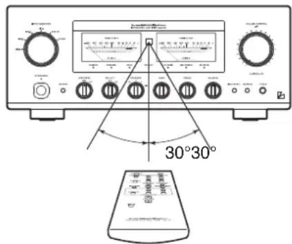
Effective distance: approx. 5 m
Dry cell
[How to load batteries]
- Put your finger on the battery cover claw on the rear of the remote control, and slide the cover downward to open it.
- Put·2·AAA·batteries·in·the·battery·case·as·shown·in·the·illustration.
3.…Close·the·battery·cover.
![LUXMAN L-550AX - [How to load batteries] - 1](/content/2026/05/1015337/images/9b357b9cdf9991a396341c9adf37bb04b10e1c653042a0f1fced240be8c347a9.jpg)
natural_image
Diagram of a device's internal structure with a directional arrow indicating rotation (no text or symbols present)*…When-the-batteries-start-to-lose-power, the-effective distance becomes shorter-or-the-unit does not function even though the switch is pressed. In such a case, both of-the-batteries shall be replaced with new ones at the same time.
*·If·the·remote·control·is·not·used·for·a·long·time,·the·batteries·shall·be·removed·from·the·case.
![LUXMAN L-550AX - [How to load batteries] - 2](/content/2026/05/1015337/images/fb4cbb6f7266c9316195b560c14002dc945e2b0a5d84d2fc39d273fe3ae75df5.jpg)
flowchart
graph TD
    subgraph_Input_Sector["Input Selector"]
        direction TB
        A["Input"] --> B["μ-COIN"]
        C["Key"] --> B
        D["LED"] --> B
    end

    subgraph_Monitoring["Monitor"]
        direction TB
        E["Phase INV/REF"] --> F["VA-20+AG"]
        G["BAL, LINE"] --> H["Phase INV/REF"]
        I["BAL, LINE"] --> J["Phase INV/REF"]
        K["REC OUT"] --> L["REC OUT"]
        M["MAIN IN"] --> N["REC OUT"]
    end

    subgraph Monitoring_Selfort
        direction TB
        O["SEG. B2"] --> P["SEPERATE"]
        Q["+H2"] --> R["MUTE"]
        S["-B2"] --> T["+"]
        U["-B2'"] --> V["+"]
    end

    subgraph Monitoring_Peak_Selfort
        direction TB
        W["REC OUT"] --> X["REC OUT"]
        Y["SEPATE"] --> Z["MUTE"]
        AA["SETE"] --> AB["MUTE"]
        AC["Time Control"] --> AD["MUTE"]
        AE["MONO"] --> AF["MUTE"]
        AG["SURFACE"] --> AH["MUTE"]
        AI["Buffer"] --> AJ["LECUA 1 LECUA 2"]
        AK["Buffer"] --> AL["LECUA 1 LECUA 2"]
        AM["Speaker selector / Protector"] --> AN["A - Speakers"]
        AO["Phone"] --> AP["B - Speakers"]
    end

    subgraph Monitoring_Peak_Selfort
        direction TB
        AQ["REC OUT"] --> AR["REC OUT"]
        AS["SEPATE"] --> AT["MUTE"]
        AU["SETE"] --> AV["MUTE"]
        AW["SETE"] --> AX["MUTE"]
        AY["REC OUT"] --> AZ["REC OUT"]
        BA["SEPATE"] --> BB["MUTE"]
        BC["SETE"] --> BD["MUTE"]
        BE["SETE"] --> BF["MUTE"]
        BG["SETE"] --> BH["MUTE"]
        BI["SETE"] --> BJ["MUTE"]
        BK["SETE"] --> BL["MUTE"]
        BM["SETE"] --> BN["MUTE"]
    end

    subgraph Monitoring_Peak_Selfort
        direction TB
        BO["REC OUT"] --> BP["REC OUT"]
        BQ["SEPATE"] --> BR["MUTE"]
        BS["SETE"] --> BT["MUTE"]
        BU["SETE"] --> BV["MUTE"]
        BW["SETE"] --> BX["MUTE"]
        BY["SETE"] --> BZ["MUTE"]
    end

    subgraph Monitoring_Peak_Selfort
        direction TB
        CA["REC OUT"] --> CB["REC OUT"]
        DC["SEPATE"] --> CE["MUTE"]
        CF["SETE"] --> CG["MUTE"]
        CH["SETE"] --> CI["MUTE"]
        CJ["SETE"] --> CK["MUTE"]
        CL["SETE"] --> CM["MUTE"]
    end

    subgraph Monitoring_Peak_Selfort
        direction TB
        CN["REC OUT"] --> CO["REC OUT"]
        CP["SEPATE"] --> CE
        CE --> CY["MUTE"]
        CZ["SETE"] --> CE
        CE --> CY
        DD["SETE"] --> CE
    end

    subgraph Monitoring_Peak_Selfort
        direction TB
        DE["REC OUT"] --> DF["REC OUT"]
        DG["SEPATE"] --> DF
        DF --> DH["MUTE"]
        DI["SETE"] --> DH
        DH --> DH
        DJ["SETE"] --> DH
    end

    subgraph Monitoring_Peak_Selfort
        direction TB
        DK["REC OUT"] --> DL["REC OUT"]
        DV["SEPATE"] --> DL
        DL --> DV
        DW["SETE"] --> DL
    end

    subgraph Monitoring_Peak_Selfort
        direction TB
        DA["REC OUT"] --> DB["REC OUT"]
        DC["SEPATE"] --> DB
        DB --> DB
        DCW["SETE"] --> DB
    end

    subgraph Monitoring_Peak_Selfort
        direction TB
        DAW["BASE"] --> DX["MUTE"]
        DXM["COS"] --> DXP["TEMP"]
        DXP --> DXP
    end

    subgraph Monitoring_Peak_Selfort
        direction TB
        DAW["W1-L"] --> DXW["PUMP"]
        DXW["PUMP"] --> DXW["PUMP"]
    end

    subgraph Monitoring_Peak_Selfort
        direction TB
        DAW["W1-R"] --> DXW["PUMP"]
        DXW["PUMP"] --> DXW["PUMP"]
    end

    subgraph Monitoring_Peak_Selfort
        direction TB
        DAW["W2-L"] --> DXW["PUMP"]
        DXW["PUMP"] --> DXW["PUMP"]
    end

    subgraph Monitoring_Peak_Selfort
        direction TB
        DAW["W2-R"] --> DXW["PUMP"]
        DXW["PUMP"] --> DXW["PUMP"]
    end

    subgraph Monitoring_Peak_Selfort
        direction TB
        DAW["W3-R"] --> DXW["PUMP"]
        DXW["PUMP"] --> DXW["PUMP"]
    end

    subgraph Monitoring_Peak_Selfort
        direction TB
        DAW["W4-R"] --> DXW["PUMP"]
        DXW["PUMP"] --> DXW["PUMP"]
    end

    subgraph Monitoring_Peak_Selfort
        direction TB
        DAW["W5-R"] --> DXW["PUMP"]
        DXW["PUMP"] --> DXW["PUMP"]
    end

    subgraph Monitoring_Peak_Selfort
        direction TB
        DAW["W6-R"] --> DXW["PUMP"]
        DXW["PUMP"] --> DXW["PUMP"]
    end

    subgraph Monitoring_Peak_Selfort
        direction TB
        DAW["W7-R"] --> DXW["PUMP"]
        DXW["PUMP"] --> DXW["PUMP"]
    end

    subgraph Monitoring_Peak_Selfort
        direction TB
        DAW["W8-R"] --> DXW["PUMP"]
        DXW["PUMP"] --> DXW["PUMP"]
    end

    subgraph Monitoring_Peak_Selfort
        direction TB
        DAW["W9-R"] --> DXW["PUMP"]
        DXW["PUMP"] --> DXW["PUMP"]
    end

    subgraph Monitoring_Peak_Selfort
        direction TB
        DAW["W10-R"] --> DXW["PUMP"]
        DXW["PUMP"] --> DXW["PUMP"]
    end

    subgraph Monitoring_Peak_Selfort
        direction TB
        DAW["W11-R"] --> DXW["PUMP"]
        DXW["PUMP"] --> DXW["PUMP"]
    end

    subgraph Monitoring_Peak_Selfort
        direction TB
        DAW["W12-R"] --> DXW["PUMP"]
        DXW["PUMP"] --> DXW["PUMP"]
    end

    subgraph Monitoring_Peak_Selfort
        direction TB
        DAW["W13-R"] --> DXW["PUMP"]
        DXW["PUMP"] --> DXW["PUMP"]
    end

    subgraph Monitoring_Peak_Selfort
        direction TB
        DAW["W14-R"] --> DXW["PUMP"]
        DXW["PUMP"] --> DXW["PUMP"]
    end

    subgraph Monitoring_Peak_Selfort
        direction TB
        DAW["W15-R"] --> DXW["PUMP"]
        DXW["PUMP"] --> DXW["PUMP"]
    end

    subgraph Monitoring_Peak_Selfort
        direction TB
        DAW["W16-R"] --> DXW["PUMP"]
        DXW["PUMP"] --> DXW["PUMP"]
    end

    subgraph Monitoring_Peak_Selfort
        direction TB
        DAW["W17-R"] --> DXW["PUMP"]
        DXW["PUMP"] --> DXW["PUMP"]
    end

    subgraph Monitoring_Peak_Selfort
        direction TB
        DAW["W18-R"] --> DXW["PUMP"]
        DXW["PUMP"] --> DXW["PUMP"]
    end

    subgraph Monitoring_Peak_Selfort
        direction TB
        DAW["W19-R"] --> DXW["PUMP"]
        DXW["PUMP"] --> DXW["PUMP"]
    end

    subgraph Monitoring_Peak_Selfort
        direction TB
        DAW["W20-R"] --> DXW["PUMP"]
        DXW["PUMP"] --> DXW["PUMP"]

    subgraph Monitoring_Peak_Selfort
            direction TB
            EQ[BASE, OC, TEMP, STOP, STOP, STOP, STOP, STOP, STOP, STOP, STOP, STOP, STOP, STOP, STOP, STOP, STOP, STOP, STOP, STOP, STOP, STOP, STOP, STOP, STOP, STOP, STOP, STOP, STOP, STOP, STOP, STOP, STOP, STOP, STOP, STOP, STOP, STOP, STOP, STOP, STOP, STOP, STOP, STOP, STOP, STOP, STOP, STOP, STOP, STOP, STOP, STOP, STOP, Stop, Stop, Stop, Stop, Stop, Stop, Stop, Stop, Stop, Stop, Stop, Stop, Stop, Stop, Stop, Stop, Stop, Stop, Stop, Stop, Stop, Stop, Stop, Stop, Stop, Stop, Stop, Stop, Stop, Stop, Stop, Stop, Stop, Stop, Stop, Stop, Stop, Stop, Stop, Stop, Stop, Stop, Stop, Stop, Stop, Stop, Stop, Stop, Stop, Stop, Top (Main Transformer)
            EQ[BASE, OC, TEMP, STOP, STOP, STOP, STOP, STOP, STOP, STOP, STOP, STOP, STOP, STOP, STOP, STOP, STOP, STOP, STOP, STOP, STOP, STOP, STOP, STOP, STOP, STOP, Stop & Stop & Stop & Stop & Stop & Stop & Stop & Stop & Stop & Stop & Stop & Stop & Stop & Stop & Stop & Stop & Stop & Stop & Stop & Stop & Stop & Stop & Stop & Stop & Stop & Stop & Stop & Stop & Stop & Stop & Stop & Stop & Stop & Stop & Stop & Stop & Stop & Stop & Stop & Stop & Stop & Stop & Stop & Stop & Stop & Stop & Stop & Stop & Stop & Stop & Stop &
            EQ[BASE,BASE,BASE,BASE,BASE,BASE,BASE,BASE,BASE,BASE,BASE,BASE,BASE,BASE,BASE,BASE,BASE,BASE,BASE,BASE,BASE,BASE,BASE,BASE,BASE,BASE,BASE,BASE,BASE,BASE,BASE,BASE,BASE,BASE,BASE,BASE,BASE,BASE,BASE,BASE,BASE,BASE,BASE,BASE,BASE,BASE,BASE,BASE,BASE,BASE,BASE,CLOSE,DISE,DISE,DISE,DISE,DISE,DISE,DISE,DISE,DISE,DISE,DISE,DISE,DISE,DISE,DISE,DISE,DISE,DISE,DISE,DISE,DISE,DISE,DISE,DISE,DISE,DISE,DISE,DISE,DISE,DISE,DISE,DISE,DISE,DISE,DISE,DISE,DISE,DISE,DISE,DISE,DISE,DISE,DISE,DISE,DISE,DISE,DISE,DISE,DISE,DISE,Dise,Dise,Dise,Dise,Dise,Dise,Dise,Dise,Dise,Dise,Dise,Dise,Dise,Dise,Dise,Dise,Dise,Dise,Dise,Dise,Dise,Dise,Dise,Dise,Dise,Dise,Dise,Dise,Dise,Dise,Dise,Dise,Dise,Dise,Dise,Dise,Dise,Dise,Dise,Dise,Dise,Dise,Dise,Dise,Dise,Dise,Dise,Dise,Dise,Dise,DaseDiseDiseDiseDiseDiseDiseDiseDiseDiseDiseDiseDiseDiseDiseDiseDiseDiseDiseDiseDiseDiseDiseDiseDiseDiseDiseDiseDiseDiseDiseDiseDiseDiseDiseDiseDiseDiseDiseDiseDiseDiseDiseDiseDiseDiseDiseDiseDiseDiseDiseDose Dose Dose Dose Dose Dose Dose Dose Dose Dose Dose Dose Dose Dose Dose Dose Dose Dose Dose Dose Dose Dose Dose Dose Dose Dose Dose Dose Dose Dose Dose Dose Dose Dose Dose Dose Dose Dose Dose Dose Dose Dose Dose Dose Dose Dose Dose Dose Dose Dose Dose C#DC#DC#DC#DC#DC#DC#DC#DC#DC#DC#DC#DC#DC#DC#DC#DC#DC#DC#DC#DC#DC#DC#DC#DC#DC#DC#DC#DC#DC#DC#DC#DC#DC#DC#DC#DC#DC#DC#DC#DC#DC#DC#DC#DC#DC#DC#DC#DC#DC#DC#BC#
            EQ[BASE,BASE,BASE,BASE,BASE,BASE,BASE,BASE,BASE,BASE,BASE,BASE,BASE,BASE,BASE,BASE,BASE,BASE,BASE,BASE,BASE,BASE,BASE,BASE,BASE,BASE,BASE,BASE,BASE,BASE,BASE,BASE,BASE,BASE,BASE,BASE,BASE,BASE,BASE,BASE,BASE,BASE,BASE,BASE,BASE,BASE,BASE,BASE,BAS-DISE-DISE-DISE-DISE-DISE-DISE-DISE-DISE-DISE-DISE-DISE-DISE-DISE-DISE-DISE-DISE-DISE-DISE-DISE-DISE-DISE-DISE-DISE-DISE-DISE-DISE-DISE-DISE-DISE-DISE-DISE-DISE-DISE-DISE-DISE-DISE-DISE-DISE-DISE-DISE-DISE-DISE-DISE-DISE-DISE-DISE-DISE-DISE-DISE-DISE-DIS(DISE)
      EQ[BASE,BASE,BASE,BASE,BASE,BASE,BASE,BASE,BASE,BASE,BASE,BASE,BASE,BASE,BASE,BASE,BASE,BAS-DISE-DISE-DISE-DISE-DISE-DISE-DISE-DISE-DISE-DISE-DISE-DISE-DISE-DISE-DISE-DISE-DISE-DISE-DIS(DISE)
      EQ[BAS-BAS-BAS-Balance(BAS) , Remote(Bas-Balance) , Reverse(Bas-Balance) , Reverse(Bas-Balance) , Reverse(Bas-Balance) , Reverse(Bas-Balance) , Reverse(Bas-Balance) , Reverse(Bas-Balance) , Reverse(Bas-Balance) , Reverse(Bas-Balance) , Reverse(Bas-Balance) , Reverse(Bas-Balance) , Reverse(Bas-Balance) , Reverse(Bas-Balance) , Reverse(Bas-Balance) , Reverse(Bas-Balance) , Reverse(BAS-Balance) , Reverse(Bas-Balance) , Reverse(Bas-Balance) , Reverse(Bas-Balance) , Reverse(Bas-Balance) , Reverse(Bas-Balance) , Reverse(Bas-Balance) , Reverse(Bas-Balance) , Reverse(Bas-Balance) , Reverse(Bas-Balance) , Reverse(Bas-Balance) , Reverse(Bas-Balance) , Reverse(Bas-Balance) , Reverse(Bas-Balance) , Reverse(Bas-BBalance) , Reverse(Bas-Balance) , Reverse(Bas-Balance) , Reverse(Bas-Balance) , Reverse(Bas-Balance) , Reverse(Bas-Balance) , Reverse(Bas-Balance) , Reverse(Bas-Balance) , Reverse(Bas-Balance) , Reverse(Bas-Balance) , Reverse(Bas-Balance) , Reverse(Bas-Balance) , Reverse(Bas-Balance) , Reverse(Bas-Balance) , Reverse(Bas-Balance) |
| Continuous power output 20 W + 20 W (8 Ω) | ||
| 40 W + 40 W (4 Ω) | ||
| Total harmonic distortion | 0.007% (8 Ω, 1 kHz both channels simultaneous drive, line straight on) | |
| 0.02% (8 Ω, 20 Hz to 20 kHz both channels simultaneous drive, line straight on) | ||
| Pre-amplifier | PHONO (MM) : 2.5 mV / 47 kΩ | |
| Input sensitivity/input impedance | PHONO (MC) : 0.3 mV / 100 Ω | |
| LINE : 180 mV / 42 kΩ | ||
| MONITOR : 180 mV / 42 kΩ | ||
| BAL. LINE : 180 mV / 79 kΩ | ||
| Main-amplifier | MAIN-IN : 450 mV / 47 kΩ | |
| Input sensitivity/input impedance | ||
| Output voltage REC OUT : 180 mV | ||
| PRE-OUT : 1 V | ||
| S/N ratio PHONO (MM) : 91 dB or more | ||
| (IHF-A weighted, 5 mV input, line straight on) | ||
| PHONO (MC) : 75 dB or more | ||
| (IHF-A weighted, 0.5 mV input, line straight on) | ||
| LINE : 105 dB or more | ||
| (IHF-A weighted, input shorted, line straight on) | ||
| Frequency response PHONO (MM) : 20 Hz to 20,000 Hz (±0.5 dB, line straight on) | ||
| PHONO (MC) : 20 Hz to 20,000 Hz (±0.5 dB, line straight on) | ||
| LINE : 20 Hz to 100,000 Hz (within - 3 dB, line straight on) | ||
| Tone control | Max. amount of change BASS : ±8 dB at 100 Hz | |
| TREBLE : ±8 dB at 10 kHz | ||
| Loudness control | 100 Hz : +7 dB | |
| 10 kHz : +5 dB | ||
| Damping factor | : 160 | |
| Accessories | · Remote control RA-17 · Power cable | |
| · Owner's Manual · Safety cautions | ||
| · size "AAA" batteries (2) | ||
| Power supply voltage | 230 V ~ (50 Hz) | |
| Power consumption | 230 W | |
| 0.4 W (at standby), 170 W (at no input) | ||
| Max. external dimensions | 440 (W) × 178 (H) × 454 (D) mm | |
| Weight | 24.3kg (main unit only) | |
* Specifications and appearance are subject to change without notice.
Before Asking for Repair Services
While the unit is used, an unusual phenomenon may be confused as a malfunction for a certain reason. Prior to asking us for repair services, please check the table below and read the instruction manual for the subsidiary devices. If the cause of the malfunction cannot be identified, please contact your dealer.
Problem Cause Solution
| No power is supplied even though the operation switch is pressed. | ·The power plug is disconnected from the wall outlet, or it is not completely inserted. | ·Insert the power plug in the wall outlet se- Insert the p curely. | |
| ·The power plug is disconnected from the AC inlet, or it is not completely inserted. | ·Insert the power plug in the AC inlet se- Insert th curely. | ||
| No sound is generated. ·The volume control is set to the minimum level. | ·Rotate the volume control clockwise to ad- Rotate the just the sound volume. | ||
| ·Set the input selector to the source to be reproduced. | |||
| ·Cable connections are incomplete. ·Make cable connections securely. | |||
| ·Adjust the output level. | |||
| ·The separate switch is set to on. ·Set the separate switch to off. | |||
| ·The mute switch of the remote control is set to on. | ·Set the mute switch to off. | ||
| No sound is generated on one side. | ·The balance control is fully rotated. | ·The balance control shall be set to the cen- ter position under normal conditions. | |
| ·The connecting cable is not connected on one side only. | ·Make cable connections securely. | ||
| Humming sound (boon or zzz noise) is generated. | ·The ground side of the pin-plug cable has no contact with the terminal. | ·Make connections securely so that the ground side of the pin-plug cable can be connected. | |
| ·The ground wire of the record player is not connected. | ·Connect the ground wire of the record play- er to the GND terminal. | ||
| ·Connections or mounting conditions are in- Connects for mounting the railings, and complete between the cartridge and shell, or between the shell and tone arm of the record player. | ·Connect the ground wire of the record play- er to the GND terminal. | ||
| No effect of tone control or bal- ance control is observed. | ·The line straight switch is set to on. | ·When tone control or balance control is used, the line straight switch shall be set to off. | |
| The subsonic, monaural or loudness is not activated. | ·The line straight switch is set to on. | ·When the subsonic, monaural or loudness is used, the line straight switch shall be set to off. | |
| The lights of the power meters are not turned on. | ·The meter switch is set to off. | ·Set the meter switch of the remote control to on. | |
| The separate switch of the remote control is not activated. | ·To prevent incorrect operations, this unit is designed to toggle the separate on/off by holding down the separate switch approxi- mately for approx. 1 second. | ·Hold down the separate switch of the re- mote control for approx. 1 second. | |
MEMO