BAKERTOP MIND.Maps - Emhætte Unox - Gratis brugsanvisning og manual
Find enhedens vejledning gratis BAKERTOP MIND.Maps Unox i PDF-format.

Brugerspørgsmål om BAKERTOP MIND.Maps Unox
0 spørgsmål om dette apparat. Besvar dem du kender, eller stil dit eget.
Stil et nyt spørgsmål om dette apparat
Download vejledningen til din Emhætte i PDF-format gratis! Find din vejledning BAKERTOP MIND.Maps - Unox og tag din elektroniske enhed tilbage i hånden. På denne side er alle dokumenter nødvendige for brugen af din enhed offentliggjort. BAKERTOP MIND.Maps af mærket Unox.
BRUGSANVISNING BAKERTOP MIND.Maps Unox
text_image
UNOX®HOOD
CHEFTOP - BAKERTOP MIND.Maps™
| XECHC-HC13 | XEVHC-CF11 |
| XECHC-HC23 | XEVHC-CF21 |
| XEVHC-HC11 | XECHC-CF13 |
| XEBHC-HCEU | XECHC-CF23 |
| XEAHC-HCFL | XEAHL-HCFL |
| XEVHC-HC21 | XECHL-HCFC |
INSTALLATION, USE AND MAINTENANCE MANUAL translation of original instructions
HOODS
SAFETY REGULATIONS FOR INSTALLATION AND MAINTENANCE .....4
SAFETY REGULATIONS FOR USE 5
EXPLANATION OF PICTOGRAMS....7
FORWARD 8
UNPACKING OF THE APPLIANCE 11
CHECKING PACK CONTENTS....13
GETTING STARTED 13
POSITIONING....14
ELECTRICAL CONNECTIONS 19
PLUMBING CONNECTIONS 21
SMOKE EXHAUST 28
HOOD AND OVEN INTERCONNECTION....30
USE 31
ROUTINE MAINTENANCE 34
INACTIVITY 36
DISPOSAL 36
CERTIFICATION 37
AFTER-SALES ASSISTANCE 38
SAFETY REGULATIONS FOR INSTALLATION AND MAINTENANCE
- Read this guide carefully before installing or maintaining the appliance, and conserve this guide with care for any future consultation of users.
- All installation, assembly and non-routine maintenance operation must be performed exclusively by qualified technicians that are authorized by UNOX, in compliance with the regulations in force in the user country, with respect to the regulations on systems and work safety.
- Before starting installation or maintenance disconnect the appliance from any electrical connections.
- Check that systems are compliant to the installation country standards and to the specifications indicated on the appliance rating plate before installing the appliance.
- Interventions, alterations or modifications not expressly authorised that do not comply with the indications in this manual shall invalidate the guarantee*.
- Installation or maintenance that fails to respect the indications in this manual may cause damage, injury or fatal accidents.
- Persons not involved with appliance installation may not pass through or occupy the work area during appliance assembly.
- Given its potential danger, the packaging material must be kept out of reach of children and animals, and correctly disposed of in compliance with local regulations.
- The ratings plate provides essential technical information that is of utmost importance for any appliance maintenance or repairs. Do not remove, damage or modify the plate.
- Failure to follow these instructions can cause damage and injury or death, voids the warranty and exempts UNOX from any liability.
SAFETY REGULATIONS FOR USE
- Following procedures other than those indicated in this guide to use and clean the appliances is considered inappropriate and may cause damage, injury or fatal accidents; in addition to invalidating the guarantee* and relieving UNOX of all liability.
- Children must not play with the appliance. Cleaning and maintenance to be implemented by the user shall not be carried out by children without supervision.
- Children must be supervised to ensure they do not play with the appliance.
- This appliance can be used exclusively:
- By qualified personnel that attend scheduled training courses;
- In combination with the UNOX electrical ovens of the CHEFTOP - BAKERTOP MIND.Maps™ line for industrial kitchens;
- For the aspiration and condensation of smoke evacuated via the oven flue;
- For smoke aspiration and evacuation that exit the oven when the door is opened.
- If the appliance does not function or if there are any functional or structural alterations, disconnect the electricity and water supplies and contact a UNOX authorized customer assistance service. Do not attempt
to independently repair the appliance. Request UNOX original spare parts for any repairs necessary.
- To ensure that the appliance is in perfect use and in a safe condition, maintenance and inspections should be performed yearly by an authorised customer agent service.
- Never use the hood without front filters!

RISK OF FIRE!
- Before using the appliance make sure that there are no non-compliant object (instruction manuals, plastic bags or other) in the oven cavity; likewise, make sure that the smoke exhaust is free of obstructions and that no flammable materials are in its vicinity.

RISK OR ELECTRICAL SHOCK
- Do not open the compartments marked with these symbols: access is reserved to qualified personnel authorised by UNOX.
- Failure to observe these regulations may cause damage and (fatal) injuries, and also invalidates the guarantee*.
HOODS Introduction
Dear Customer,
We would like to congratulate and thank you for choosing to purchase an appliance in the CHEFTOP - BAKERTOP MIND.Maps™ range; we hope this is just the beginning of a fruitful and long-lasting partnership.
These ovens are the climax of Unox research and guarantee minimum occupation of space with superlative performance while offering outstanding cooking management at any condition of use and load.
EXPLANATION OF PICTOGRAMS
The installation and user instructions are valid for all models unless otherwise specified by the following pictograms:

Danger! Situation presenting immediate danger, or a hazardous situation which could cause injury or death.
Danger: fire hazard!
Tips and useful information
Danger: electric shock!
Earthing symbol
Read the instruction manual
Equipotential symbol
Danger: risk of burns
Consult other chapter
FORWARD
This appliance can be used exclusively:
- by qualified personnel that attend scheduled training courses;
- in combination with UNOX electrical ovens of the CHEFTOP - BAKERTOP MIND.Maps™ line for industrial kitchens (for more information see "Table A" on page 8);
- for the aspiration and condensation of smoke evacuated via the oven flue;
- for smoke aspiration and evacuation that exit the oven when the door is opened.

We recommend you thoroughly read this manual for all instructions on how to maintain the aesthetic and functional qualities of your purchased product intact.
Table A
| HOOD MODEL | COUPLING WITH COMBINED OVEN'S OF THE RANGE |
| XECHC-HC13 | CHEFTOP MIND.MapsTM COMPACT GN1/3 ovens |
| XECHC-HC23 | CHEFTOP MIND.MapsTM COMPACT GN2/3 ovens |
| XEVHC-HC11 | GN1/1 counter top ovens |
| XEBHC-HCEU | 600x400 counter top ovens |
| XEAHC-HCFL | GN1/1 & 600x400 free standing ovens |
| XEVHC-HC21 | GN2/1 counter top ovens |
| XEVHC-CF11 | GN1/1 counter top ovens |
| XEVHC-CF21 | GN2/1 counter top ovens |
| XECHC-CF23 | CHEFTOP MIND.MapsTM COMPACT GN2/3 ovens |
| XECHC-CF13 | CHEFTOP MIND.MapsTM COMPACT GN1/3 ovens |
| XEAHL-HCFL | BIG ovens |
| XECHL-HCFC | BIG COMPACT ovens |
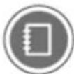
① cold water supply thermically controlled by a temperature sensor
② UNOX.Det&Rinse detergent supply
③ residual water discharge
4 cavity moisture released from underlying oven flues
5 vapour condenser
6 2-speed aspiration motor
⑦ cavity moisture released from open door
8 exiting cold air
9 RJ45 cable: connects the hood to the oven
10 plug for connection to the electricity mains
XEVHC-CF11 - XEVHC-CF21
XECHC-CF23 - XECHC-CF13
text_image
Technical diagram of a device with numbered components and labeled parts, including a component with 'in' and 'out' labels.
text_image
Technical diagram of a device assembly with labeled parts and connections, including hood and oven components.
UNPACKING OF THE APPLI- ANCE
Check the package for any visible damage. If damage is found, immediately contact UNOX and DO NOT install the appliance.
Before transporting the appliance to its installation point, make sure that:
- it easily passes through doorways;
- the floor supports its weight.
Transport must be exclusively performed by mechanical means (i.e. transpallet fork-lift).

Given its potential danger, the packaging material must be kept out of reach of children and animals, and correctly disposed of in compliance with local regulations.
natural_image
Illustration of various workplace and safety items including boots, hard hats, gloves, and a human figure (no text or symbols)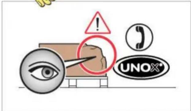
text_image
Safety warning illustration with icons for eye, phone call, UNOX, and warning symbol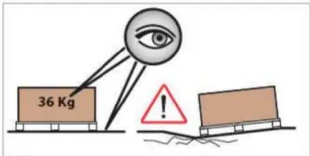
text_image
36 Kg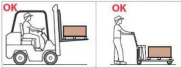
text_image
OK OK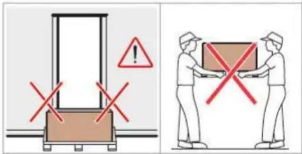
text_image
Safety warning illustration showing a door lock system with red X marks and warning symbols, alongside a delivery worker carrying a box.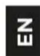
NON-STOP Efforts
UNOX has followed the NON-STOP Efforts philosophy for years to increase the environmental compatibility of its products to reduce energy consumption and wastes.
UNOX wishes to protect the environment and invites the consumer to dispose of waste in recycling bins.
text_image
CARDBOARD NYLON CARDBOARD WOOD POLYESTYRENE
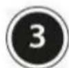
CHECKING PACKAGE CONTENTS
Before installing the appliance, check that the following packaged components are present and free of damage.

Contact UNOX if a component is missing or damaged.
① hood pre-fitting for:
• electrical connections (power supply cable already assembled);
- plumbing connections;
- connection to a CHEFTOP - BAKERTOP MIND.Maps™ oven (RJ45 cable pre-assembled);
② 50mm exhaust pipe (30mm for compact ovens);
③ metal clips;
④ screws; ⑤ siphon support bracket;
⑥ technical documentation (use and maintenance booklet);
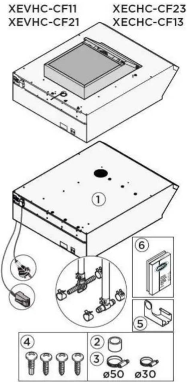
GETTING STARTED
Removing the film
Slowly remove the protective films from the appliance: clean any glue residues with appropriate solvents without using tools, abrasive detergents or acids that could ruin the surfaces.

The removed film, given its potential danger, must be kept out of reach of children and animals; and correctly disposed of in compliance with local regulations.
text_image
XEVHC-CF11 XEVHC-CF21 XECHC-CF23 XECHC-CF13 ① ⑥ ⑤ ④ ② ③ ø50 ø30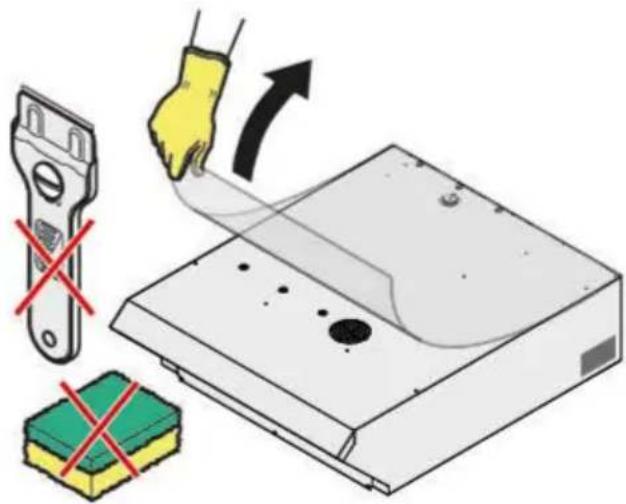
text_image
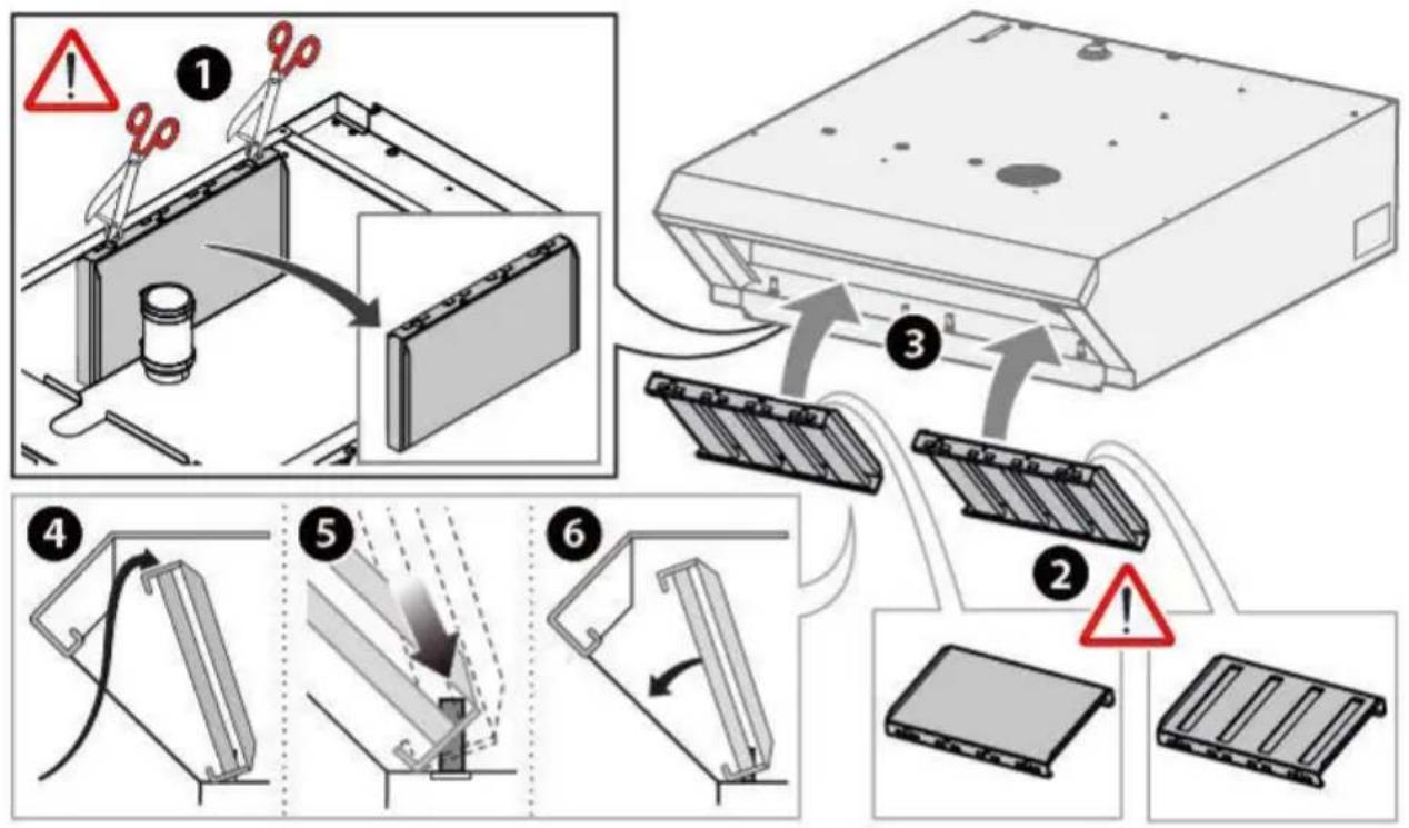
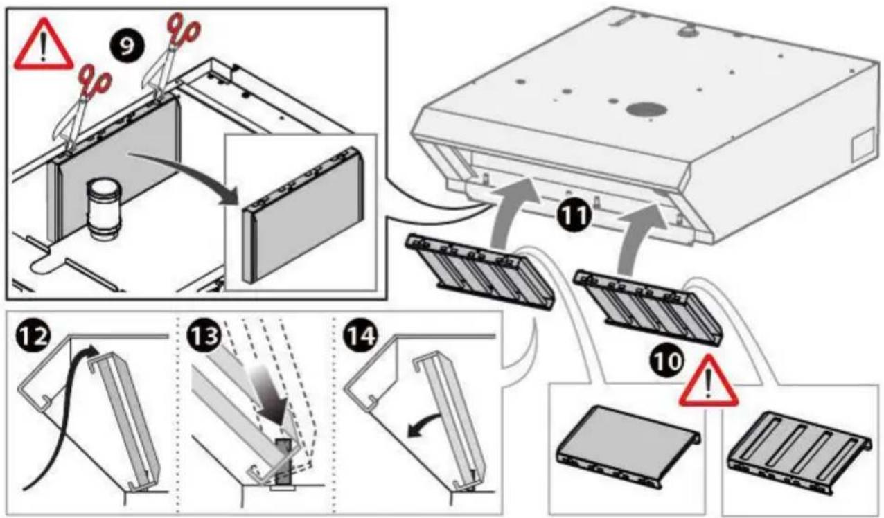
Diagram illustrating a hand using a tool to cut a device with red X marks, showing no text or symbols.Installation of filters (BIG oven hoods EXCLUDED)
Make sure filters are correctly positioned during installation (the filter with slots on both sides must be placed in correspondence to the handle so that the steam is aspirated as soon as the oven door is opened).
flowchart
graph TD
    A["1: Mounting with 10% mark"] --> B["2: Assembly with 3% mark"]
    B --> C["3: Cover with 2% mark"]
    C --> D["4: Disassembly with 5% mark"]
    D --> E["5: Breakdown with 6% mark"]
    E --> F["6: Final packaging with 7% mark"]
    style A fill:#f9f,stroke:#333
    style B fill:#ccf,stroke:#333
    style C fill:#cfc,stroke:#333
    style D fill:#fcc,stroke:#333
    style E fill:#cff,stroke:#333
    style F fill:#ffc,stroke:#333
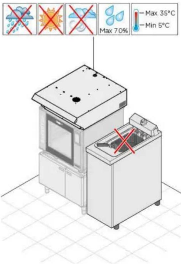
POSITIONING
Characteristics of the installation area
Install the appliance in areas:
- dedicated and conforming to the cooking of industrial foods;
- having adequate air ventilation;
- that comply with the laws in your country;
- protected against the weather;
- with temperatures between +5° to +35°C maximum;
- having a maximum humidity of 70%.
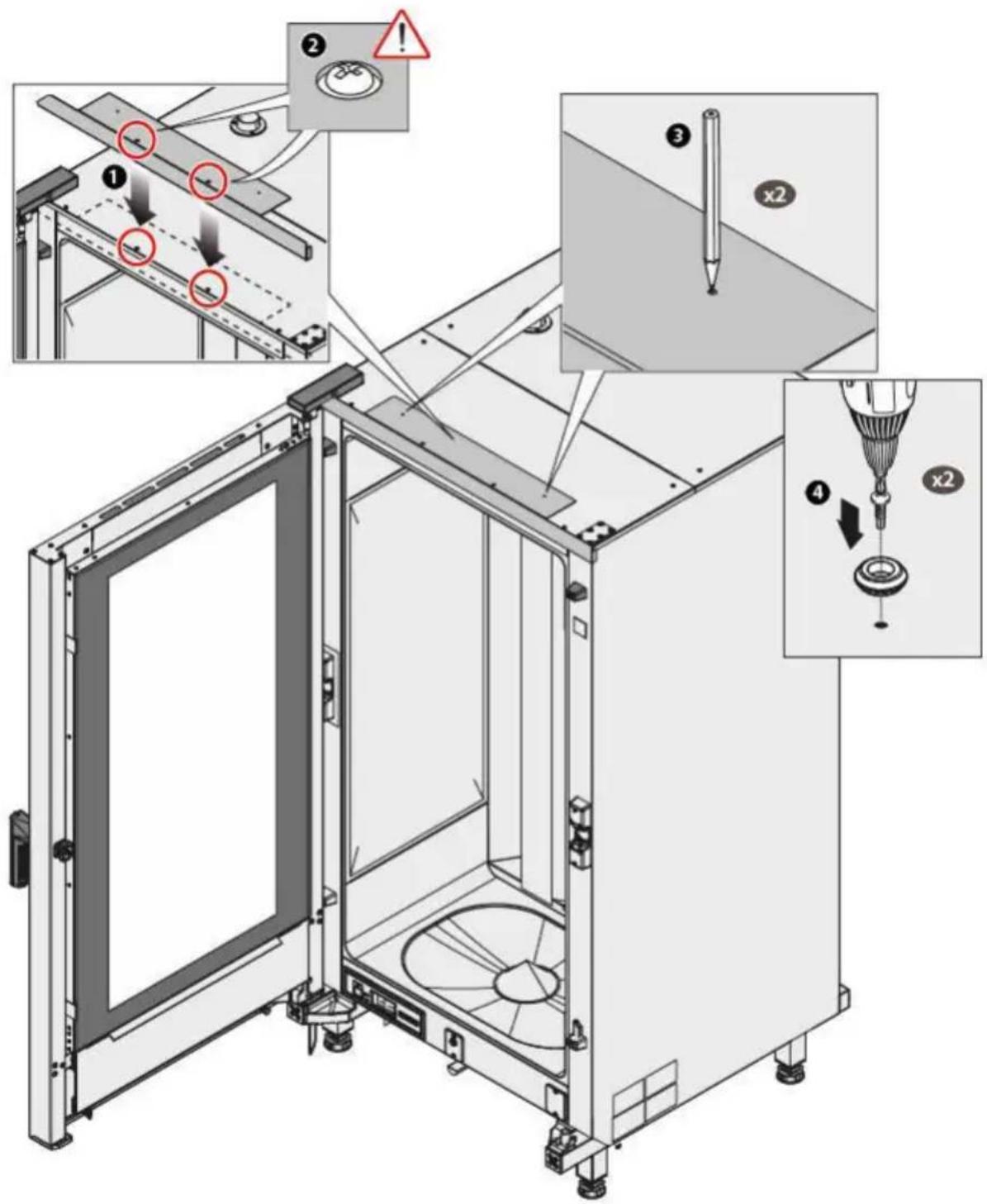
The appliances must only be positioned on top of CHEFTOP - BAKER-TOP MIND.Maps™ model electrical ovens and fixed to them according to the method indicated in section "Anchoring to bottom-stacked ovens" on page 16.
text_image
Max 70% — Max 35°C — Min 5°C
The appliance is not suited for recessed installation.
Make sure that the floor can support the weight of the appliance coupled to the equipment below (see "Table B" on the side).
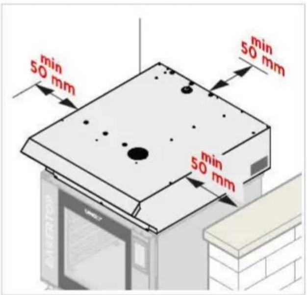
Appliance distances
Position the appliance respecting the indicated distances in the diagram and so that the back of the oven is easily accessible for appliance connections and maintenance.

Do not install the appliance near flammable or heat sensitive materials, walls or furniture. Otherwise, protect them with appropriate non-flammable materials in compliance with fire prevention regulations - see diagram below.
Table B
| MODELS | Size (LxWxH) | Weight kg |
| XECHC-HC13 | 535x900x240 | 20 |
| XECHC-HC23 | 535x1100x240 | 20 |
| XEVHC-HC11 | 750x956x240 | 23 |
| XEBHC-HCEU | 860x1145x240 | 25 |
| XEAHC-HCFL | 868x1159x240 | 30 |
| XEVHC-HC21 | 868x1323x240 | 36 |
| XEVHC-CF11 | 750x956x366 | 30 |
| XEVHC-CF21 | 868x1323x366 | 43 |
| XECHC-CF23 | 535x1100x366 | 27 |
| XECHC-CF13 | 535x900x366 | 27 |
| XEAHL-HCFL | 892x1131x239 | 35 |
| XECHL-HCFC | 650x1208x342 | 25 |
text_image
min 50 mm min 50 mm min 50 mm MAXIST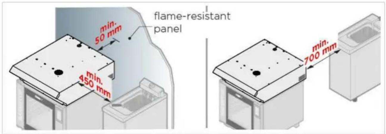
text_image
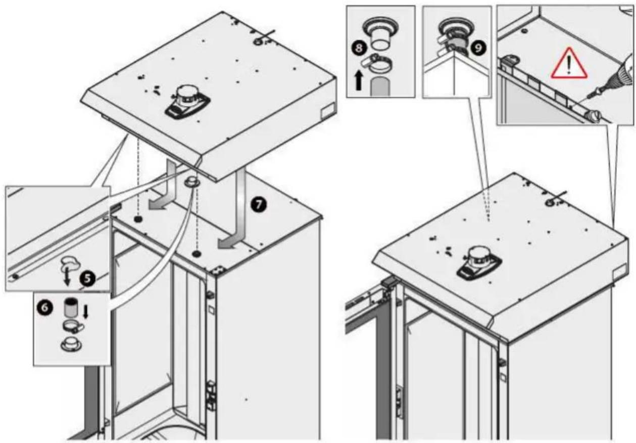
min. 50 mm min. 450 mm flame-resistant panel min. 700 mmAnchoring to bottom-stacked ovens

For sake of practicality, we recommend performing rear connections after having made electrical, plumbing and smoke flue connections.
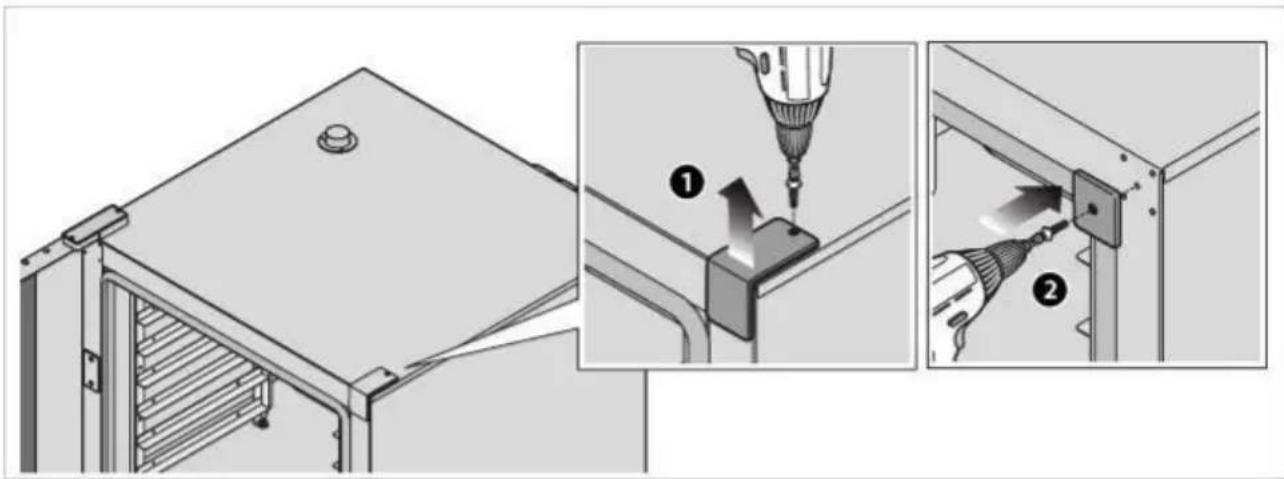
text_image
Technical diagram showing installation steps of a mechanical component with labeled parts and tool path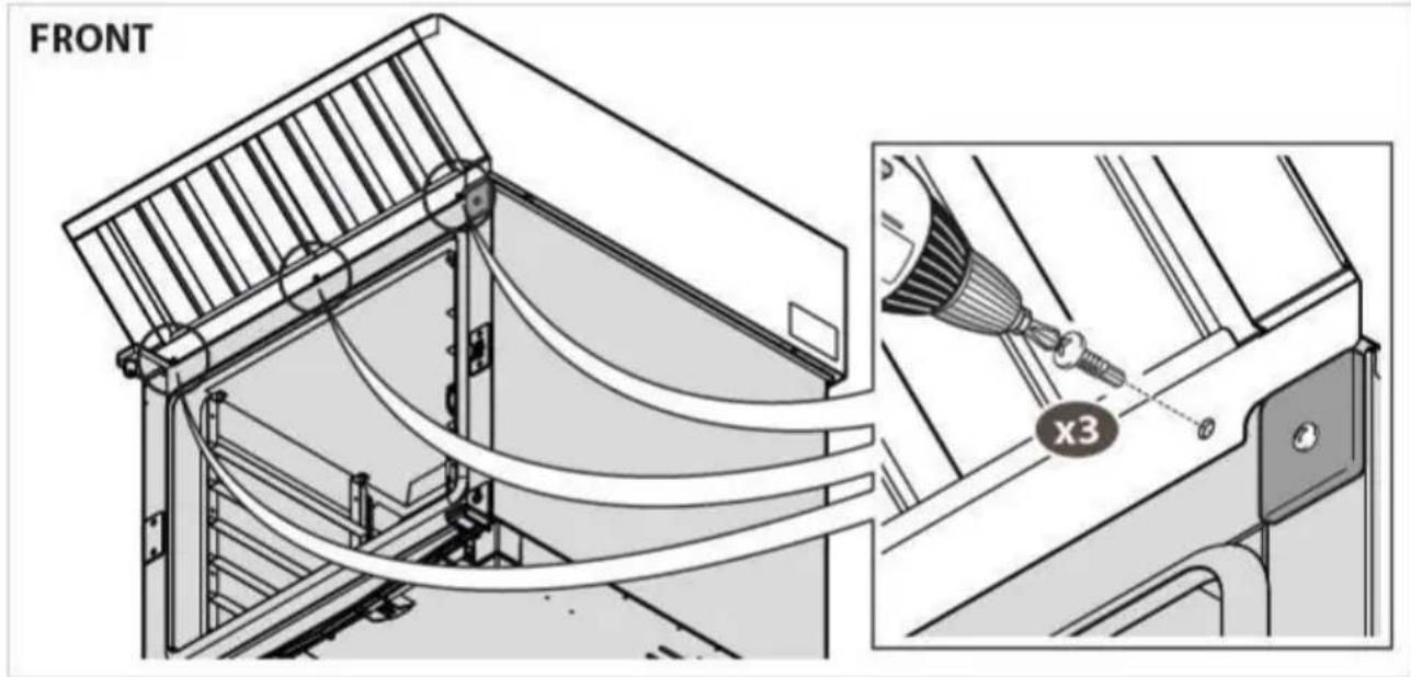
text_image
FRONT x3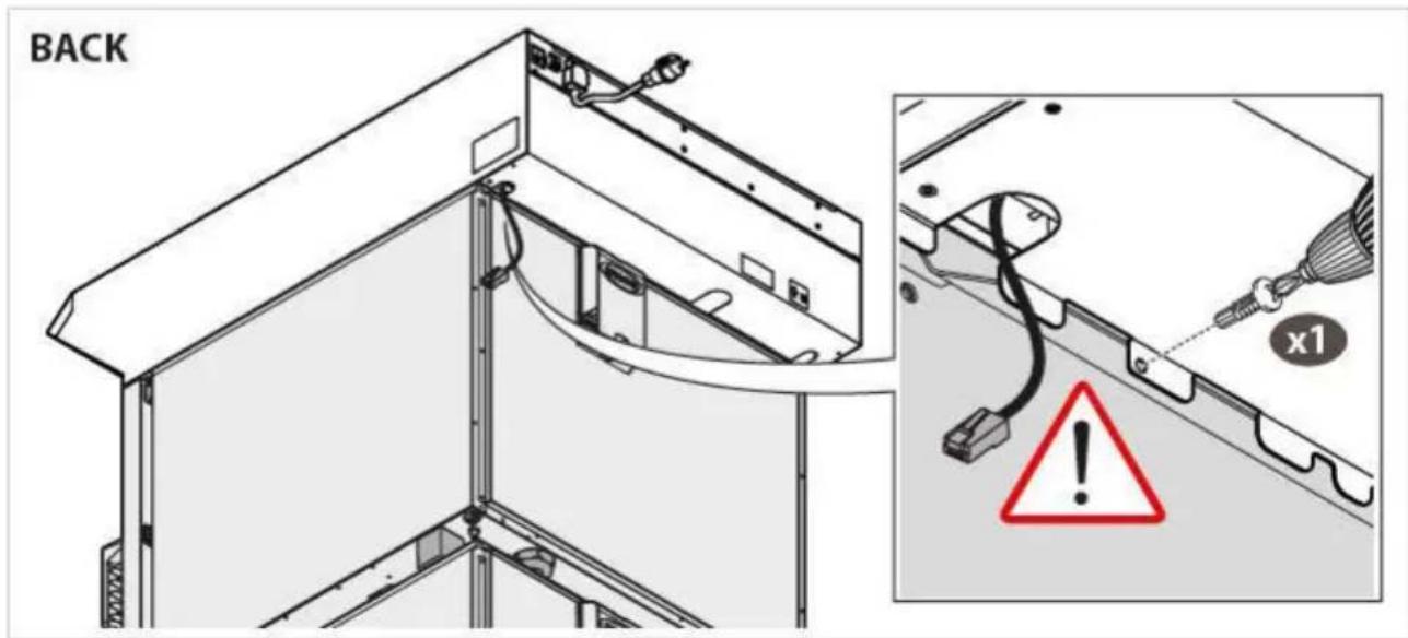
text_image
BACK x1Anchoring to bottom-stacked ovens for BIG ovens

For sake of practicality, we recommend performing rear connections after having made electrical, plumbing and smoke flue connections.
text_image
Technical diagram showing a 3D printing machine with labeled components and warning indicators for installation or repair.Anchoring to bottom-stacked ovens for BIG ovens
text_image
Technical diagram illustrating the installation of a mechanical device with numbered components and warning labels in Chinese.Installation of filters (ONLY hoods provided on BIG ovens)
Make sure filters are correctly positioned during installation (the filter with slots on both sides must be placed in correspondence to the handle so that the steam is aspirated as soon as the oven door is opened).
flowchart
graph TD
    A["Warning"] --> B["Step 9: Mounting a component"]
    B --> C["Step 10: Assembly of battery pack"]
    C --> D["Step 11: Cover or package"]
    D --> E["Step 12: Panel assembly with cable"]
    E --> F["Step 13: Breakdown of battery pack"]
    F --> G["Step 14: Assembly of battery pack"]
    G --> H["Final packaging"]
ELECTRICAL CONNECTIONS
Before installing the appli- ance carefully read section "Safety regulations for installation and maintenance" on page 4.

Connections to the main power and the electrical system must comply with the regulations in force in the country of installation of the appliance; and all connections must be performed by qualified personnel authorised by UNOX. Failure to comply with these regulations may cause damage and injuries, invalidates the guarantee* and relieves UNOX of all liabilities.
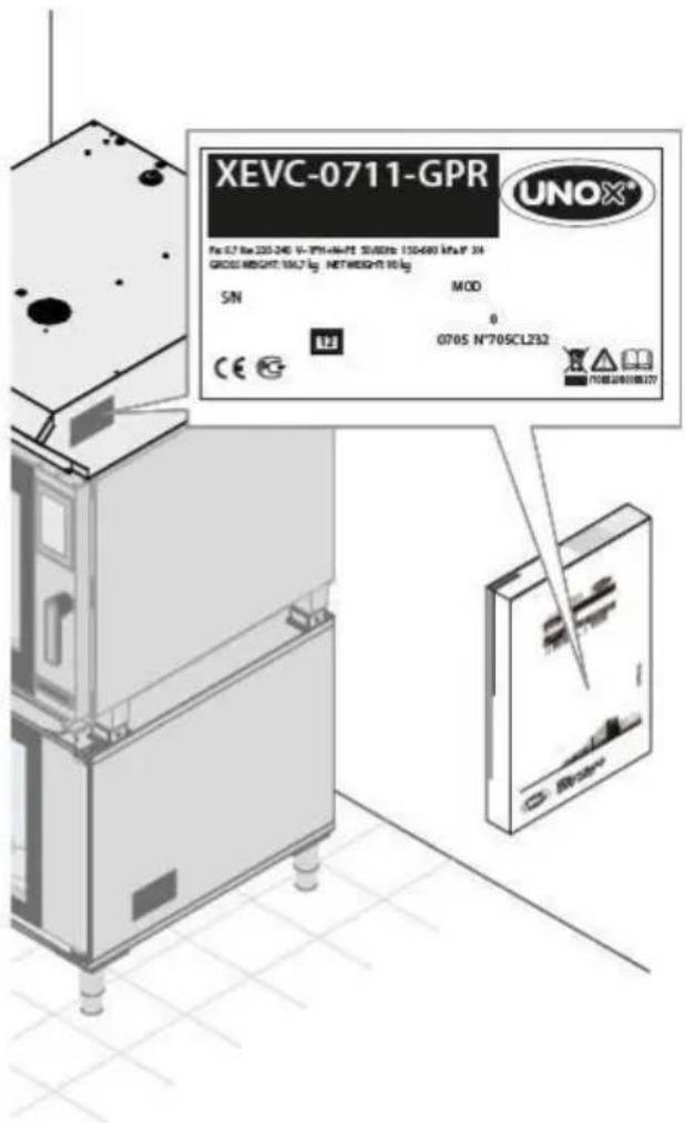
text_image
XEVC-0711-GPR XEVC-0711-GPR UNOX® Pin: 67.8kV 220-240 V~375kVA/PT SUSSN: 120-680 kVA/PT 24 GROSS WEIGHT: 100,7 kg NETWEIGHT: 90 kg SN MOD 0 CE UH 0705 N°70SCL232 代碼: 24000000000000000000000000000000000000000000000000000000000000000000000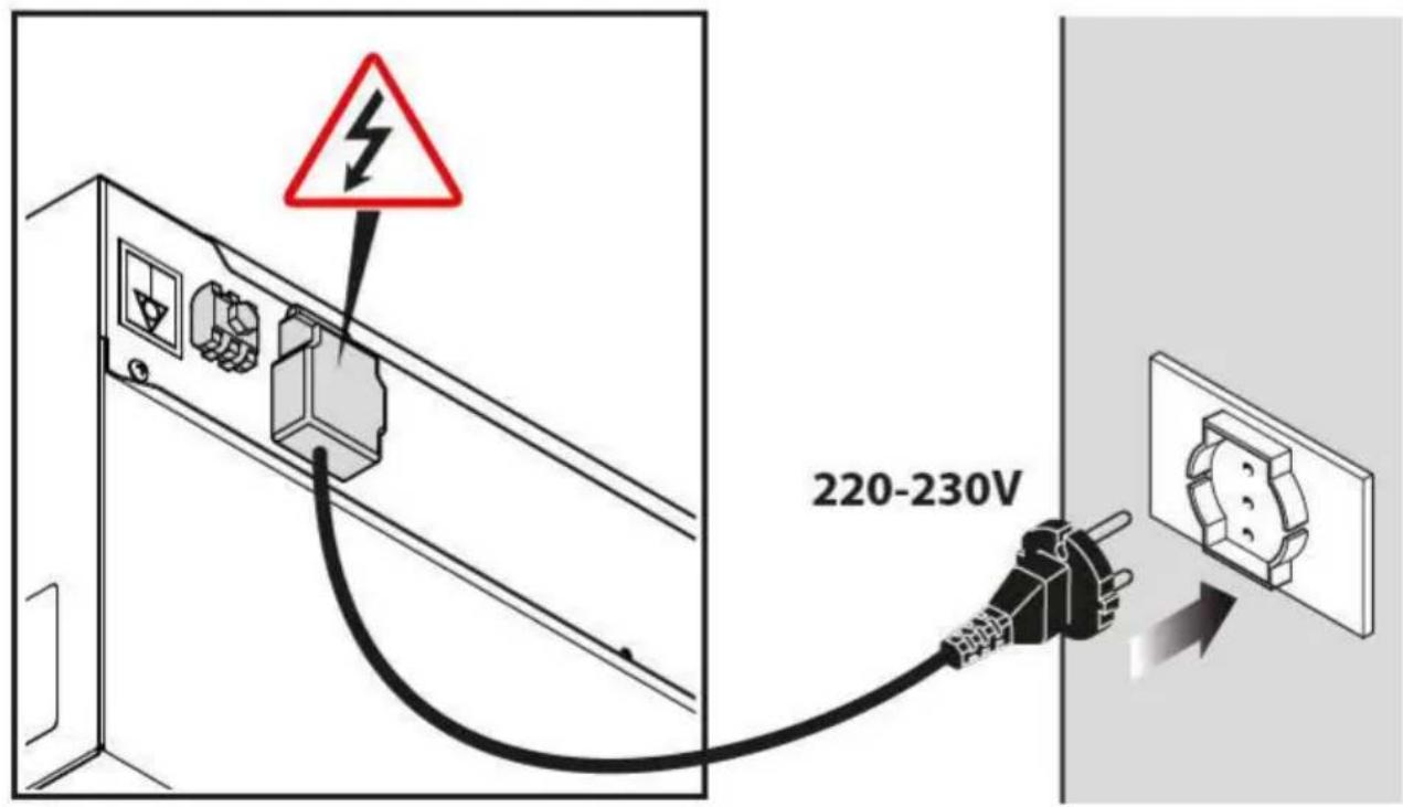
text_image
220-230V*Please visit the Warranty section of the Unix Web site (www.unox.com) for further details
Before connecting the appliance to the mains electricity, always compare the power supply data with that of the appliance specified on the rating plate.
The appliance is released from the factory with power cable and plug already connected to the terminal. Do not make any other type of electrical connection and no dimensional modification of the cable other than extensions, replacing it only with one having specifications equal to the original factory cable (type of rummer, cross-section, etc.).

The cable must be replaced by UNOX or by its technical assistance service, and in all cases by a person with similar qualification in order to avoid possible risks.

The wiring diagrams, wire specifications and the technical data are indicated on the "Technical specifications" sheet attached to the appliance.
For proper electrical connections, the appliance must:
- Be wired into an equipotential system in accordance with current regulations. This connection must be performed between different appliances with the terminal marked with the equipotential symbol. The cable must have a maximum cross-section of 10 mm2 (pursuant standard CEI EN 60335-2-42:2003-09) and be of yellow-green colour.
- Must be grounded ⏚ to the earthing (green-yellow wire).
- Must be connected to a thermal differential switch in compliance with the regulations in force (0.03A Type A).
- Must be connected to a omni polar circuit breaker mechanism that enables complete disconnection in category III over voltage conditions.
Checks
- The copper jumper in the terminal board and the electrical cable must be secured together under the screw in its tightening direction; and the electrical connections must be securely tightened before connecting the appliance to the electricity mains.
- Check for any electrical dispersion between the phases and the ground, and for electrical continuity between the external casing and the main ground line.
- Check that the power supply voltage does not deviate from the nominal voltage value specified on the appliance rating plate when the appliance is operating. If this is not the case, wire the phases as specified on the "technical specifications" sheet attached.
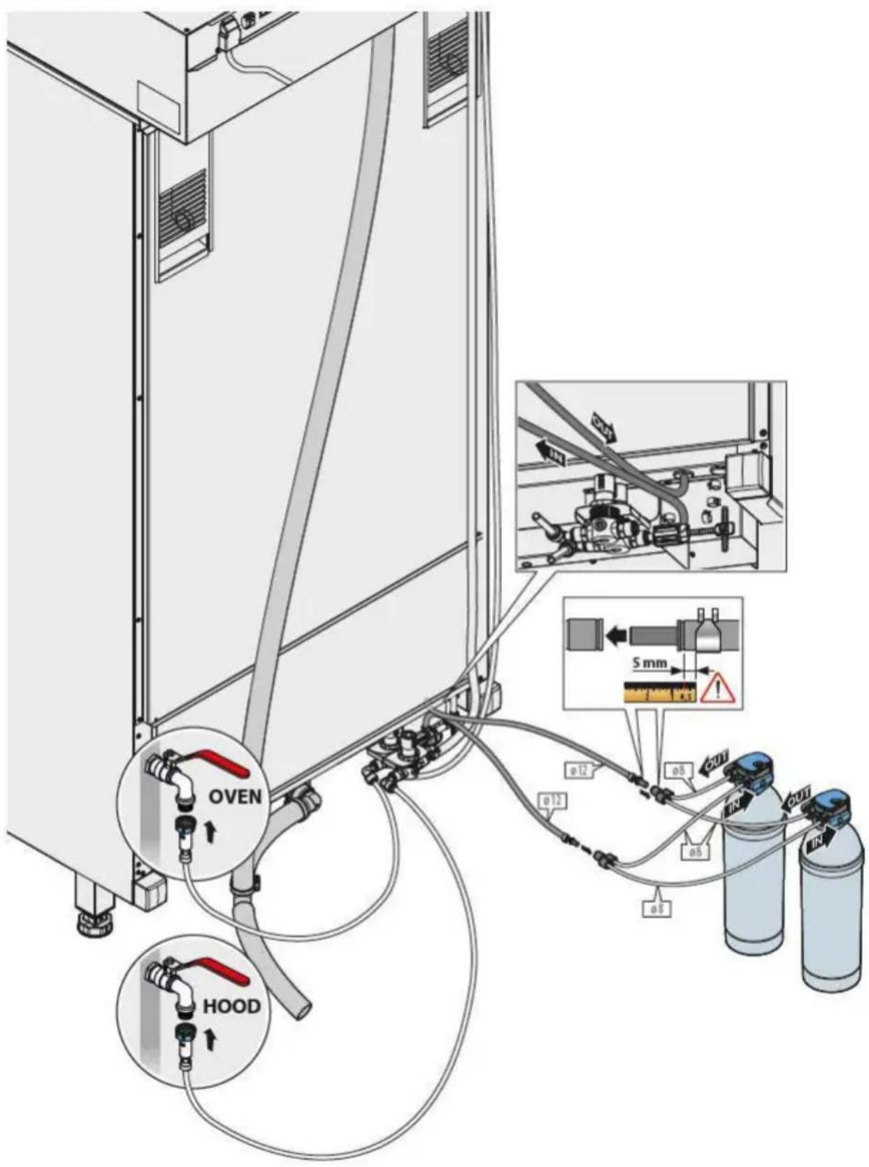
HYDRAULIC CONNECTIONS
Inlet water
The back of the device is equipped with:
A two meters of pipe with a tee coupling for the connection to the oven inlet supply (already fitted with a mechanical filter and the (3/4") fitting with non-return valve). B a pipe to supply the detergent to wash the filters.
Before connecting the water pipe to the appliance, flush it out with water in order to eliminate any residue which has accumulated inside it.
A shut off valve should be positioned between the water mains and the appliance;
The new hose-sets supplied with the appliance are to be used for the connection to the water supply. Old hose-sets should not be reused.
For further information, refer to the instructions inside the CHEFTOP - BAKERTOP MIND.
Maps™ oven packaging.
INLET WATER CHARACTERISTICS

Any damage caused by using water with parameters that do not correspond to what is specified in this section is not covered by the guarantee.
Inlet water must have the following specifications:
- maximum water temperature of 30 °C;
- water of drinking quality;
- water pressure between 150 and 600 kPa (we recommend 200 kPa).

If the inlet water pressure is lower than the indicated value (150kPa) use a pump with adequate capacity (minimum flow 300 l/h).
Inflow water specifications WASHING circuit:
Free chlorine ≤ 0,1 ppm
Chloramine ≤ 0,1 ppm
TDS ≤ 125 ppm
Silica ≤ 12 ppm
pH 7 ÷ 8,5
Total hardness (TH) ≤ 15°d
Chlorides ≤ 35 ppm
Alkalinity ≤ 200 ppm as CaCO _3
Should the water values for the WASH circuit differ from those shown, treat the water entering the system as necessary.
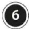
Once the connections are made, make sure the rubber plug (tied to the hood with a string) is in position. The plug is above the hood liquid drain and is useful if the drain gets blocked so that the vapour condenser can be inspected.
text_image
Diagram showing a device with a warning sign and an inset image of a mechanical component with a cable.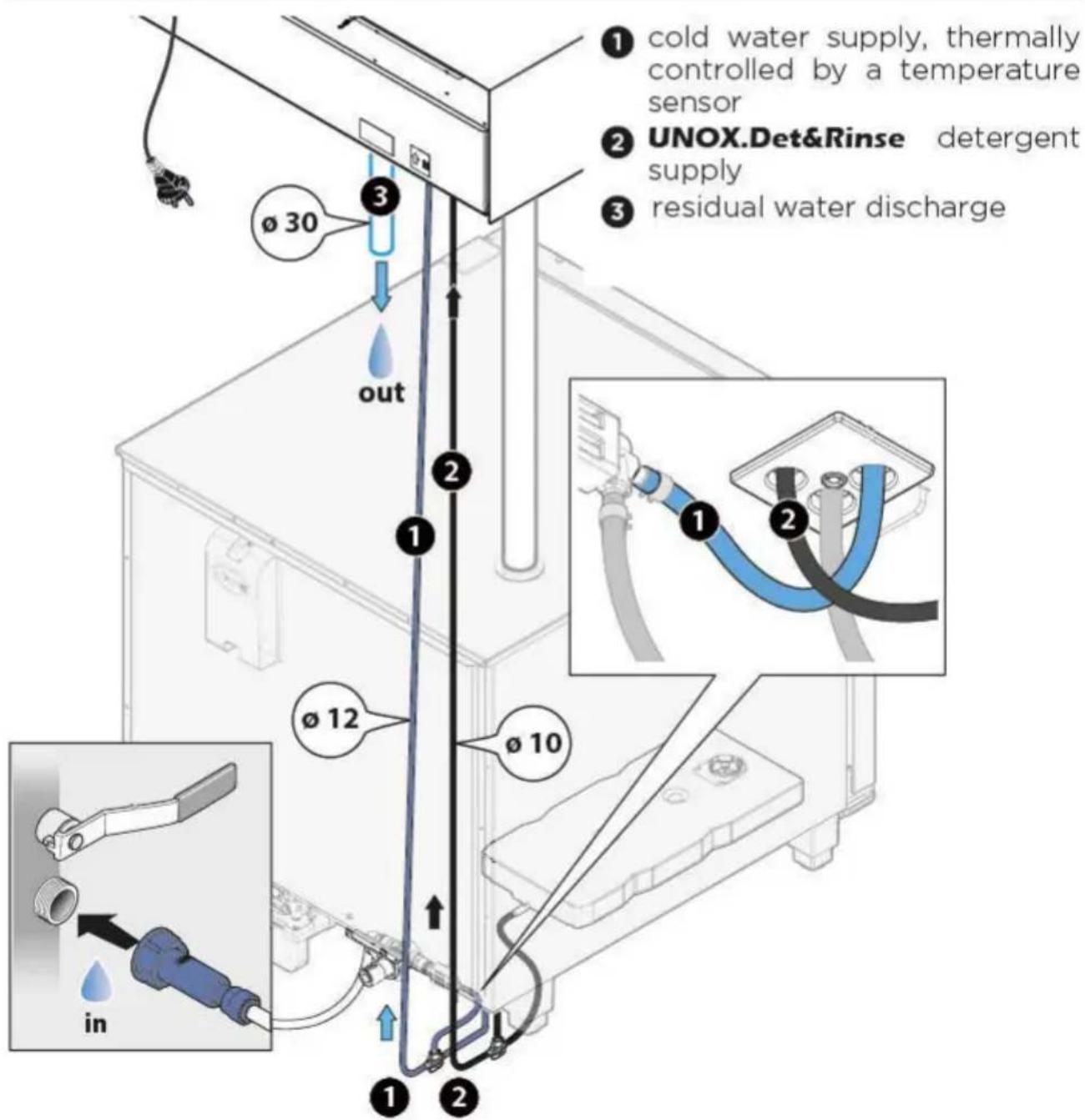
text_image
① cold water supply, thermally controlled by a temperature sensor ② UNOX.Det&Rinse detergent supply ③ residual water discharge out ① ② ③ ④ ⑤ ⑥ ⑦ ⑧ ⑨ ⑩ ⑪ ⑫ ⑬ inBIG ovens
text_image
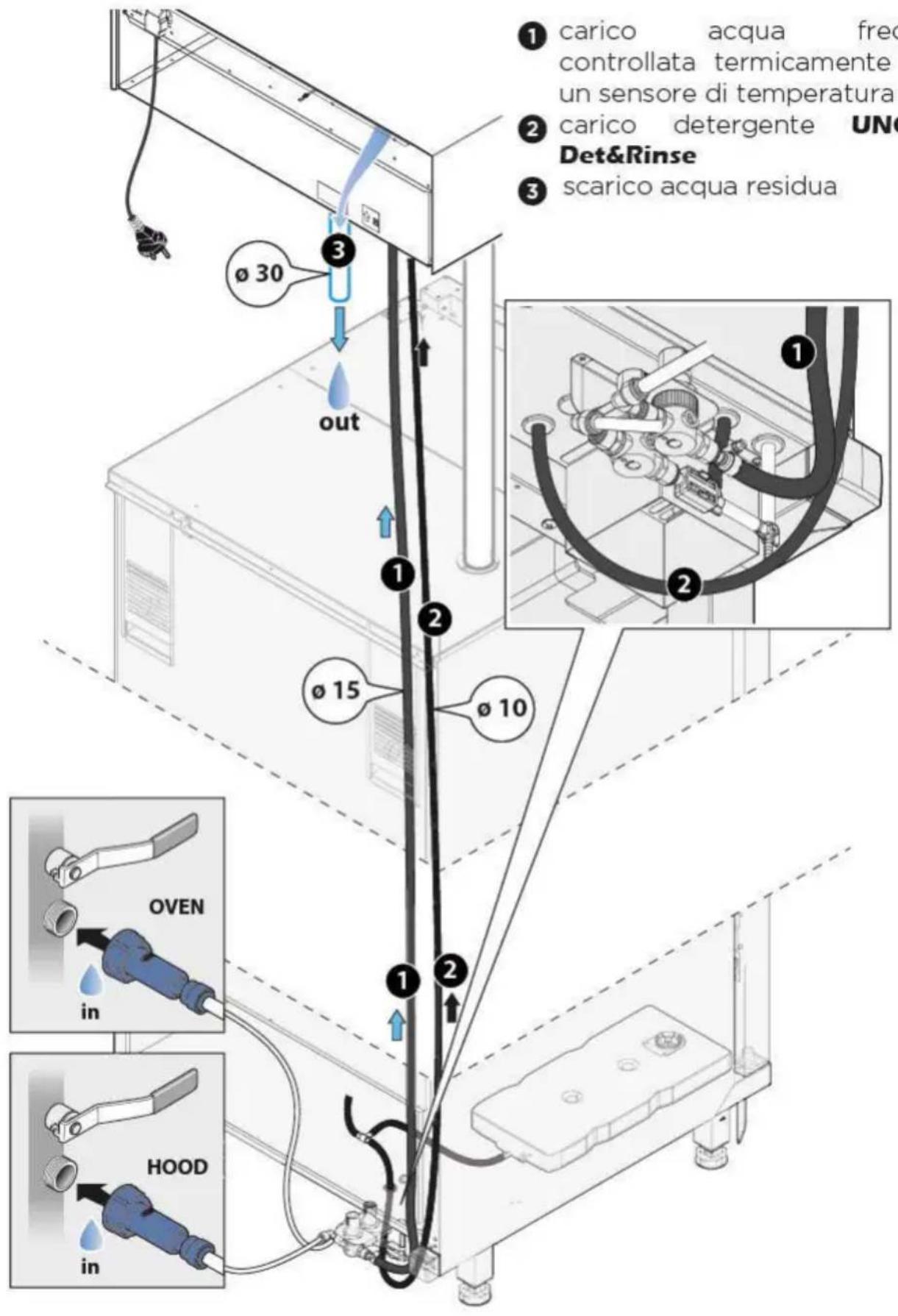
① carico acqua freccontrollata termicamenteun sensore di temperatura ② carico detergente UNoDet&Rinse ③ scarico acqua residua ø 30 out ① ② ø 15 ø 10 ① ② OVEN in HOOD in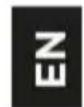
flowchart
graph TD
    A["UNOX.Pure"] --> B["LOVEN FORNO"]
    B --> C["HOOD CAPPA"]
    C --> D["LOVEN FORNO"]
    D --> E["LIEVITATORE PROOFER"]
    subgraph LOVEN FORNO
        F["IN A"] --> G["OUT B"]
        H["IN A"] --> I["OUT B"]
        J["IN A"] --> K["OUT B"]
        L["IN A"] --> M["OUT B"]
        N["IN A"] --> O["OUT B"]
        P["IN A"] --> Q["OUT B"]
        R["IN A"] --> S["OUT B"]
        T["IN A"] --> U["OUT B"]
        V["IN A"] --> W["OUT B"]
        X["IN A"] --> Y["OUT B"]
        Z["IN A"] --> AA["OUT B"]
        AB["IN A"] --> AC["OUT B"]
        AD["IN A"] --> AE["OUT B"]
        AF["IN A"] --> AG["OUT B"]
        AH["IN A"] --> AI["OUT B"]
        AJ["IN A"] --> AK["OUT B"]
        AL["IN A"] --> AM["OUT B"]
        AN["IN A"] --> AO["OUT B"]
        AP["IN A"] --> AQ["OUT B"]
        AR["IN A"] --> AS["OUT B"]
        AT["IN A"] --> AU["OUT B"]
        AV["IN A"] --> AW["OUT B"]
        AX["IN A"] --> AY["OUT B"]
        AZ["IN A"] --> BA["OUT B"]
        BB["IN A"] --> BC["OUT B"]
        BD["IN A"] --> BE["OUT B"]
        BF["IN A"] --> BG["OUT B"]
        BH["IN A"] --> BI["OUT B"]
        BJ["IN A"] --> BK["OUT B"]
        BL["IN A"] --> BM["OUT B"]
        BN["IN A"] --> BO["OUT B"]
        BP["IN A"] --> BQ["OUT B"]
        BR["IN A"] --> BS["OUT B"]
        BT["IN A"] --> BU["OUT B"]
        BV["IN A"] --> BW["OUT B"]
        BX["IN A"] --> BY["OUT B"]
        BZ["IN A"] --> CA["OUT B"]
        CB["IN A"] --> CC["OUT B"]
        DD["IN A"] --> EE["OUT B"]
        FF["IN A"] --> DG["OUT B"]
        DH["IN A"] --> DI["OUT B"]
        DJ["IN A"] --> DK["OUT B"]
        DL["IN A"] --> DM["OUT B"]
        DN["IN A"] --> DOG["OUT B"]
        DOG --> DP["LOVEN FORNO"]
    end
    subgraph LOVEN FORNO
        Q1["B"] --> R1["D"]
        R1 --> S1["E"]
        S1 --> T1["T"]
    end
    subgraph LOVEN FORNO
        U1["B"] --> V1["D"]
        V1 --> W1["T"]
    end
    subgraph LOVEN FORNO
        X1["D"] --> Y1["T"]
    end
    subgraph LOVEN FORNO
        Z1["D"] --> AA1["A"]
    end
    subgraph LOVEN FORNO
        AB1["A"] --> AC1["D"]
    end
    subgraph LOVEN FORNO
        AD1["A"] --> AE1["E"]
    end
    subgraph LOVEN FORNO
        AF1["A"] --> AG1["A"]
    end
    subgraph LOVEN FORNO
        AH1["A"] --> AI1["A"]
    end
    subgraph LOVEN FORNO
        AJ1["A"] --> AK1["A"]
    end
    subgraph LOVEN FORNO
        AL1["A"] --> AM1["A"]
    end
A: Untreated water (to Unox.Pure/Unox. Pure-RO)
B: Treated water (from Unox.Pure/Unox. Pure-RO)
C: Connection to the detergent tank
D: Cleaning water (untreated)
E: Incoming water
BIG ovens
text_image
OVEN HOOD 5 mm 5 mm 12 12 12 12 12 12 12 12 12 12 12 12 12 12 12 12 12 12 12 12 12 12 12 12 12 12 12 12 12 12 12 12 12 12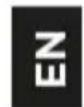
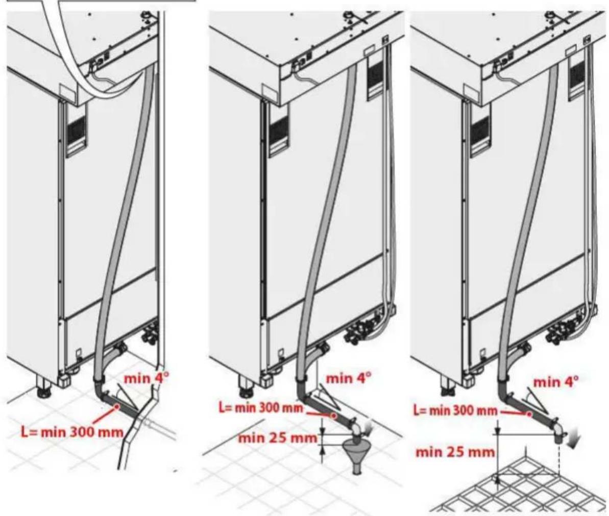
Outgoing water
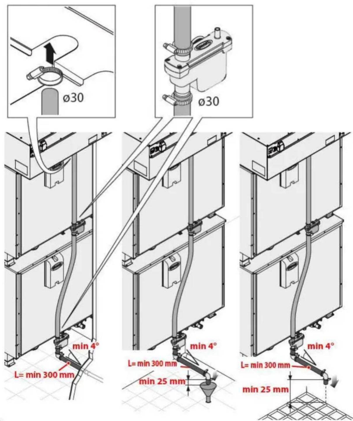
Plumbing connections are on the rear of the appliance: connect the attachment to a rigid pipe or hose by using a metal clip (supplied) and connect to a waste water discharge.

UNOX recommends its proprietary rigid pipes and flexible hoses.

The waste water draining from the appliance may be hot (90°C). The pipes used for water drainage must be able to withstand high temperatures.
text_image
Ø30 Ø30 min 4° L= min 300 mm min 4° L= min 300 mm min 25 mm min 4° L= min 300 mm min 25 mm
text_image
Ø30Outgoing water
BIG ovens
text_image
min 4° L= min 300 mm min 4° L= min 300 mm min 25 mm min 4° L= min 300 mm min 25 mmDrainage specifications
The drainage system must:
- be a siphon-type;
- be one meter in length maximum;
- have a minimum incline of 4%;
- have a diameter that is NOT less than the drain pipe attachment;
- be dedicated to each appliance; if this is not the case, make sure that the main drainage pipe is sized sufficiently to ensure that water flows away properly without any problems;
- be free of kinks and sharp ends.

For additional information see the instructions contained inside your CHEFTOP - BAKERTOP MIND.Maps™ packaging.
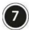
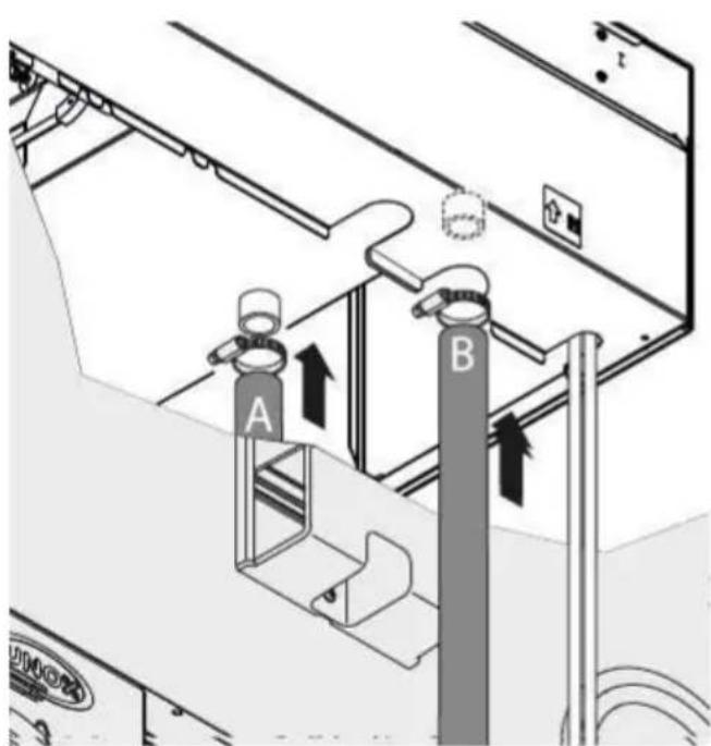
SMOKE EXHAUST
Connection to oven smoke flues
Cooking produces hot smoke and odours that are evacuated through an exhaust pipe on the top portion of the appliance.
Stacked ovens require that both the top and bottom ovens be connected to the hood.
The unused smoke intakes of the hood must be sealed using the plugs supplied.

UNOX recommends its ex-haust pipes.
text_image
Technical diagram showing airflow or ventilation system with labeled components A and B, including directional arrows indicating flow direction.
text_image
Technical schematic diagram of a mechanical or electrical device with labeled components A and B, showing internal components and assembly lines.Hood smoke exhaust
Smoke and odours coming from the oven cavity are evacuated through the hood smoke flues
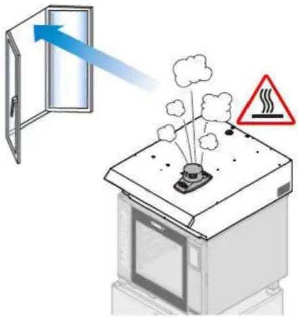
External evacuation can be performed in 1 of 3 manners:
1) Direct evacuation in the oven installation area.

Make sure that no objects or materials that may obstruct fume evacuation or become damaged by the temperature or fumes are placed above the smoke exhaust. Do not leave flammable materials near the smoke exhausts.
2) Evacuation through an efficient ventilation flue.
The UNOX smoke flue must be installed.
The flue must preferably have the same diameter (ø12cm) throughout the entire length of the oven's exhaust pipe connection;

We recommend a flue cover be installed on top of the external end of the flue, to prevent rainwater from getting into the oven and to minimise pressure drops caused by the Venturi effect, which can occur during strong air currents.
3) Evacuation by activated charcoal filter (CF)
Hoods with a final CF code have the filter already installed. the activated charcoal filter can however be purchased separately
natural_image
Illustration of a kitchen appliance with smoke and heat transfer symbols (no text or labels)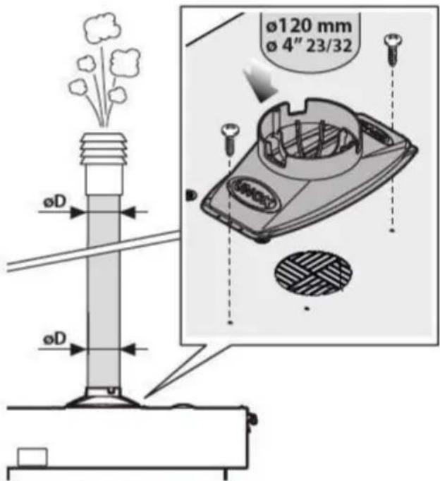
text_image
Ø120 mm Ø 4" 23/32 ØD ØD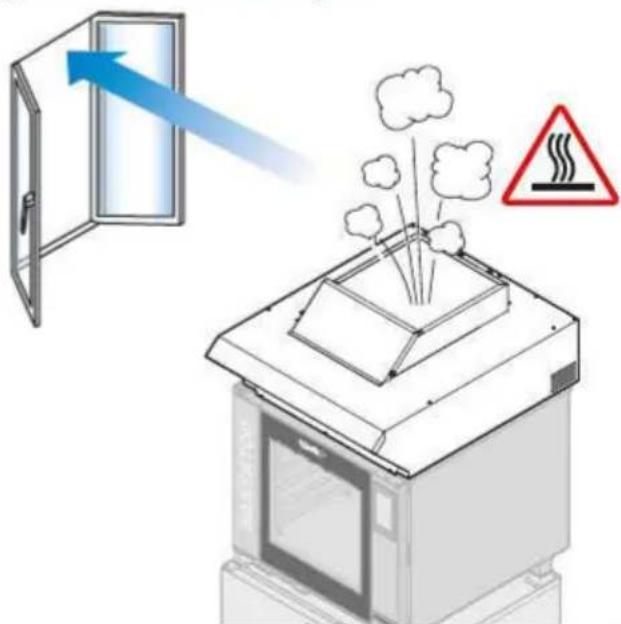
natural_image
Diagram showing airflow from a door to a machine with smoke and warning symbol (no text or labels)
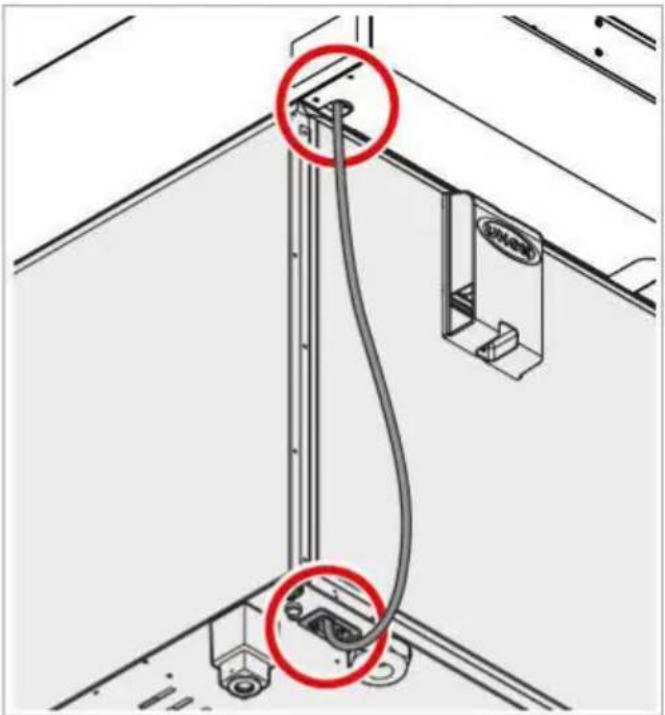
HOOD AND OVEN INTER- CONNECTION
The hoods are designed to be connected to CHEFTOP-BAKERTOP MIND.Maps™ ovens.
The accessories connect to the oven by means of ModBus connectors located on the back of the oven, which automatically connect.
① Disconnect all appliance from the electricity mains.
② Remove the rear panel of the oven to access the power board.
③ Connect the RJ45 cable to one of the ModBus outlets corresponding to the power board.
④ Replace the rear panel of the ovens.
⑤ Reconnect all the appliances to the electricity mains.

Follow the instructions contained in the accessory packing for information on to fully install and manage

Connect the ModBus cables only to the relative ModBus connectors and not to the Ethernet connectors.
natural_image
Technical diagram showing cable installation with two red-circled points of interest, no text or symbols present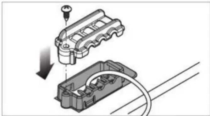
natural_image
Mechanical assembly diagram showing a piston-cranked engine block being inserted into a cable (no text or symbols present)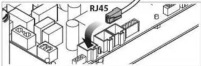
text_image
RJ45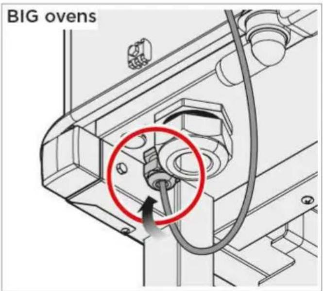
text_image
BIG ovensHOODS
Use

Before using the appliance:
- carefully read the section "Safety regulations for installation and maintenance" on page 4.
USE

Clean thoroughly at first oven use (see chapter "Routine maintenance" on page 34).
Operate the appliance at a room temperature between +5°C and +35°C.
The appliances do not feature a control panel because they are automatically controlled by the oven to which they are connected via RJ45 cable 9.
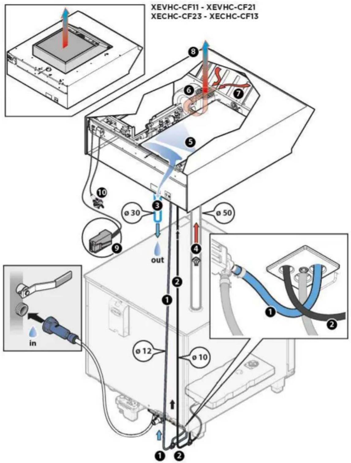
During cooking (manual or scheduled), the hood automatically starts at minimum speed: cold water is loaded ① and the condensing system, ⑤ which reduces the fumes coming from the underlying oven flues, starts ④. The mitigated smoke is evacuated in liquid form via a pipe on the back of the appliances ③. The hood speed increases when the oven door is opened in order to aspirate frontal smoke that escapes from the oven door ⑦.
Use the UNOX.Det&Rinse 2 detergent to ensure perfect cleaning of the condenser.
text_image
XEVHC-CF11 - XEVHC-CF21 XECHC-CF23 - XECHC-CF13 8 6 7 5 3 10 ø 30 out 9 ø 50 2 1 ① ② ① ② ø 12 ø 10 in① cold water supply thermically controlled by a temperature sensor
② UNOX.Det&Rinsedetergent supply
③ residual water discharge
④ cavity moisture released from flues of ovens below
⑤ vapour condenser
6 2-speed aspiration motor
⑦ cavity moisture released from open door
8 exiting cold air
9 RJ45 cable: connects the hood to the oven
10 plug for connection to the electricity mains
text_image
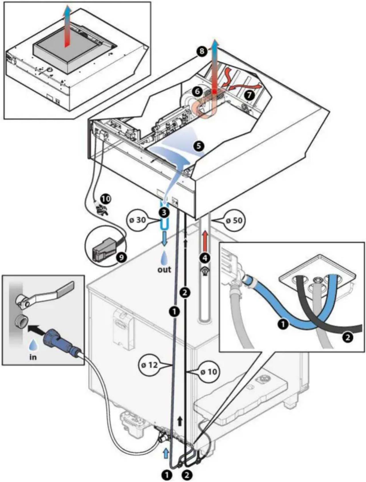
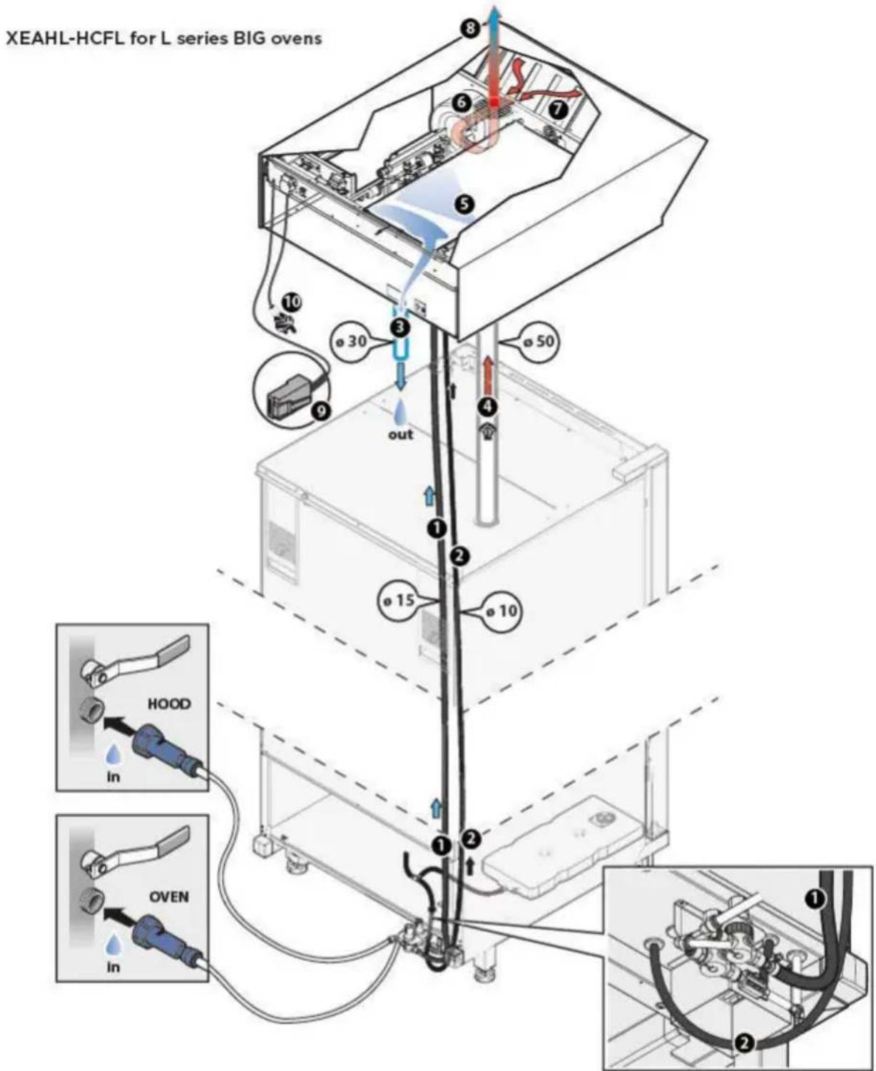
XEAHL-HCFL for L series BIG ovens 8 6 7 5 30 50 out 10 9 1 2 15 10 HOOD in OVEN in① cold water supply thermically controlled by a temperature sensor
② UNOX.Det&Rinsedetergent supply
③ residual water discharge
④ cavity moisture released from flues of ovens below
5 vapour condenser
6 2-speed aspiration motor
⑦ cavity moisture released from open door
8 exiting cold air
9 RJ45 cable: connects the hood to the oven
10 plug for connection to the electricity mains
ROUTINE MAINTENANCE

Any routine maintenance procedure must be performed:
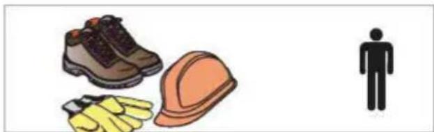
- after disconnecting the appliance from the power and water supplies - after having put on the proper personal protection equipment (i.e. gloves, etc...).
Do NOT clean using:
- abrasive or powder detergents;
- aggressive or corrosive detergents (i.e. hydrochloric/muriatic or sulphuric acid).
- abrasive or sharp tools (i.e. abrasive sponges, scrapers, steel bristled brushes, etc...);
- water spray.
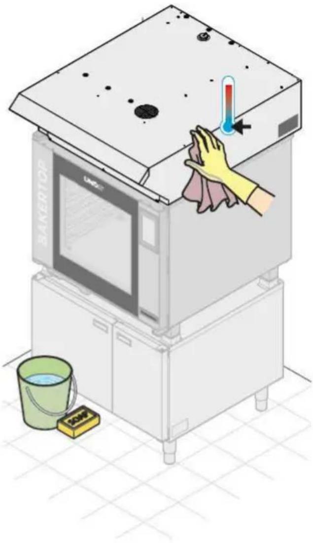
External steel surfaces
Wait for the surfaces to cool off.
Use only a soft cleaning cloth dampened with a little soap and water. Rinse and dry completely. In alternative, only use detergents recommended by UNOX; other products may cause damage thereby invalidating the guarantee*. Read the instructions provided by the detergent producer for their use.
natural_image
Illustration of a kitchen appliance with a hand cleaning it, showing a thermometer and a bucket on the floor (no text or symbols)External front filters
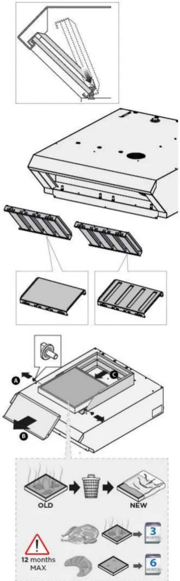
Wait for the filters to cool off.
The front filters must be removed from time to time as shown in the figure and washed with soapy water or in the dishwasher.
Make sure that they are completely dry before re-mounting them.

Never use the hood without front filters!
Internal vapour condenser
The internal condenser is automatically washed at the end of each oven washing without the need for operator intervention.

Before each washing make sure that the detergent tank (located under an oven) is not y.
We recommend using only UNOX. Det&Rinse detergent by UNOX.
UNOX.Det&Rinse is the UNOX solution that offers both detergent and rinse aid in a single product, otherwise sold separately. The working principle of UNOX.Det&Rinse combines the degreasing action of detergents and the power of rinse aid to obtain the best results during oven washing and rinsing.
Activated charcoal filter replacement
The instructions to replace the filter are given for CF hoods supplied with activated charcoal filters, such as:
XEVHC-CF11
XEVHC-CF21
XECHC-CF13
XECHC-CF23
text_image
Technical diagram illustrating the installation and cleaning process of a device, showing steps from raw material inspection to final packaging with time indicators.INACTIVITY
Follow the precautions below during inactivity:
- disconnect the appliance from the power and water supplies;
- we recommend rubbing a soft cloth lightly doused with mineral oil on all stainless steel surfaces;
At first reuse:
- clean the appliance and its accessories thoroughly (see chapter "Routine maintenance" on page 34);
- connect the appliance to its power and water supplies;
- inspect the appliance before using it;

To ensure that the appliance is in perfect use and in a safe condition, maintenance and inspections should be performed yearly by an authorised customer agent service.
DISPOSAL
Pursuant to article 13 of Legislative Decree 49 of 2014 "Implementation of the WEEE Directive 2012/19/EU on electrical and electronic equipment waste",
The barred symbol of the rubbish bin specifies that the product was placed on the market after August 13, 2005 and that at the end of its useful life it should not be treated as other waste, but must be collected separately.
All appliances are made with recyclable metallic materials (stainless steel, iron, aluminium, galvanized steel, copper, etc.) in percentages higher than 90% by weight.
Make the appliance ready for disposal by removing the power cable and any compartment or cavity closure latch (where present). At the end of its useful life, this product must be managed in a way that reduces the negative impacts on the environment and improves the effectiveness of use of resources by applying the "the polluter pays", prevention, preparation for reuse, recycling and recovery principles. Please remember that illegal or incorrect disposal of the product leads to the application of the penalties provided by current legal provisions.
Information on disposal in Italy
In Italy, WEEE appliances must be delivered:
- to Collection Centres (also known as ecological islands or ecological platforms)
- to the dealer from whom new appliances are purchased, who is required to collect them free of charge ("one against one" collection);
Information on disposal in countries of the European Union
The EU Directive on WEEE appliances has been implemented differently by each country. Therefore, if you want to dispose of this appliance, we recommend you contact your local authorities or dealer to get information on the correct disposal method.
CERTIFICATION
EU declaration of conformity for electrical and gas appliances
Manufacturer: UNOX S.p.A.
Address: Via Majorana, 22 - 35010 Cadoneghe, Padua, Italy
Declares, under its own responsibility, that the products:
XECHC-HC13
XECHC-HC23
XEVHC-HC11
XEBHC-HCEU
XEAHC-HCFL
XEVHC-HC21
XEVHC-CF11
XEVHC-CF21
XECHC-CF13
XECHC-CF23
XEAHL-HCFL
XECHL-HCFC
comply with Machinery Directive 2006/42/EC that is compliant with the following standards:
EN 60335-1: 2014 +A11:2014
EN 60335-2-99: 2003
EN62233: 2008
comply with EM Compatibility Directive 2014/30/EC through the following standards:
EN 55014-1: 2006 + A1: 2009 + A2: 2011
EN 55014-2: 1997 + A1: 2001 + A2: 2008
EN 61000-3-2: 2006 + A1: 2009 + A2: 2009
EN 61000-3-3: 2008
EN 61000-3-11: 2000
EN 61000-3-12: 2011
EN 61000-6-2: 2005
EN 61000-6-3: 2007

AFTER-SALES ASSISTANCE
In case of any malfunctions, disconnect the appliance from its power and water supply. Consult the solutions proposed in the table.
text_image
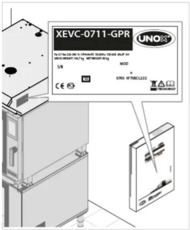
XEVC-0711-GPR Pc 0.7 Rm 228-260 V-10PM/HPPE 35/50Hz 120-400 MPa IP 34 GROSS WEIGHT: 186,7 kg NET WEIGHT: 90 kg S/N MOD 124 0 0705 N°705CL232If the solution is not listed in the table, contact a UNOX authorized technical customer service. Provide the following information:
- the date of purchase;
- the appliance data on the serial plate;
- any alarm messages that are shown on the display of the oven connected to the hood.
Manufacturer's information:
UNOX S.p.A.
Via Majorana, 22
35010 Cadoneghe (PD) Italy
Tel +39 049 86.57.511
Fax +39 049 86.57.555
info@unox.com www.unox.com
| Malfunction | Possible cause | Problem solution |
| The hood cannot be engaged when a cooking cycle is started. | The hood is not connected to the power supply. | Connect the hood to the power supply. |
| The hood was not connected to the oven vis RJ45 cable during installation. | Contact the Customer Assistance Service | |
| The RJ45 cable that connects the oven to the hood is disconnected or damaged. | ||
| The hood motor is faulty. | ||
| The motor starter capacitor is faulty. | ||
| The hood P.C.B. is damaged. | ||
| The oven P.C.B. is damaged. | ||
| The oven P.C.B. is damaged. | ||
| The hood does not achieve maximum speed when the oven door is opened. | The RJ45 cable is disconnected or damaged. | Contact the Customer Assistance Service |
| The hood motor is faulty. | ||
| The hood P.C.B. is damaged. | ||
| The oven P.C.B. is damaged. | ||
| The oven P.C.B. is damaged. | ||
| Door switch faulty. | ||
| Malfunction Possible cause Problem | solution | |
| The water condensation system is faulty. | Water inlet closed. | Open water inlet. |
| Plumbing has not been done correctly. | Make sure the appliance is connected to the water supply. | |
| The water intake filter is clogged by impurities. | Clean the filter. | |
| The water intake solenoid is damaged. | Contact the Customer Assistance Service | |
| The temperature sensor is damaged. | ||
| The hood P.C.B. is damaged. | ||
natural_image
Exterior view of a modern industrial building with a large UNO badge on the facade (no signage visible)INTERNATIONAL
UNOX S.p.A.
Via Majorana 22 / 35010 Cadoneghe (PD) Italy
Tel +39 049 8657511 / Fax +39 049 8657555
info@unox.com
INVENTIVE SIMPLIFICATION
| EUROPE | ASIA & AFRICA | ||
| ITALIAUNOX S.p.A.E-mail: info@unox.itTel.: +39 049 86 57 511 | DEUTSCHLANDUNOX DEUTSCHLAND GmbHE-mail: info.de@unox.comTel.: +49 2951 98760 | MALAYSIA & SINGAPOREUNOX (ASIA) SDN. BHDE-mail: info.asia@unox.comTel.: +603-58797700 | U.A.E.UNOX MIDDLE EAST DMCEE-mail: info.uae@unox.comTel.: +971 52 304 3321 |
| ČESKÁ REPUBLIKAUNOX DISTRIBUTION s.r.o.E-mail: info.cz@unox.comTel.: +420 241 940 000 | FRANCE, BELGIUM & LUXEMBOURGUNOX FRANCE s.a.s.E-mail: info@unox.frTel.: +33 4 78 17 35 39 | OTHER ASIAN COUNTRIESUNOX (ASIA) SDN. BHDE-mail: info.asia@unox.comTel.: +603-58797700 | SOUTH AFRICAUNOX SOUTH AFRICAE-mail: info.sa@unox.comTel.: +27 845 05 52 35 |
| POCCIIA, ПРИБАТИКА И СТРАНЫ СНГUNOX РОССИЯE-mail: info.ru@unox.comTel.: +7 (499) 702-00-14 | ÖSTERREICHUNOX ÖSTERREICH GmbHE-mail: bestellung@unox.comTel.: +43 800 880 963 | PHILIPPINESUNOX PHILIPPINESE-mail: info.asia@unox.comTel.: +63 9173108084 | INDONESIAUNOX INDONESIAE-mail: info.asia@unox.comTel.: +62 81908852999 |
| ESPAÑAUNOX PROFESIONAL ESPAÑA S.L.E-mail: info.es@unox.comTel.: +34 900 82 89 43 | HRVATSKAUNOX CROATIAE-mail: narudzbe@unox.comTel.: +39 049 86 57 538 | 대한민국UNOX KOREA CO. Ltd.이메알: info.asia@unox.com전화: +82 2 69410351 | 中华人民共和国UNOX TRADING (SHANGHAI) CO. Ltd.电子邮件: info.china@unox.com电话: +86 21 56907696 |
| SCANDINAVIAN COUNTRIESUNOX SCANDINAVIA ABE-mail: info.se@unox.comTel.: +46 (0)768 716 422 | TÜRKİYEUNOX TURKEY Protestonel Mutrak Ekip-markan Endostri ve Ticaret Limited ŞirkatiE-mail: info.tr@unox.comTel.: +90 530 176 62 03 | AMERICA & OCEANIA | |
| UNITED KINGDOMUNOX UK Ltd.E-mail: info@unoxuk.comTel.: +44 1252 851 522 | IRELANDUNOX IRELANDE-mail: info.ie@unox.comTel.: +353 (0) 87 32 23 218 | U.S.A. & CANADAUNOX Inc.E-mail: infousa@unox.comTel.: +1 800 489 8669 | COLOMBIAUNOX COLOMBIAE-mail: info.co@unox.comTel.: +57 350 65 88 204 |
| PORTUGALUNOX PORTUGALE-mail: info.pt@unox.comTel.: +351 918 228 787 | БЪЛГАРИЯUNOX BULGARIAE-mail: info.bg@unox.comTel.: +359 88 23 13 378 | MEXICOUNOX MEXICO, S. DE R.L. DE C.V.E-mail: info.mx@unox.comTel.: +52 1555 4314 180 | AUSTRALIAUNOX AUSTRALIA PTY Ltd.E-mail: info@unoxaustralla.com.auTel.: +61 3 9876 0803 |
| BRAZILUNOX BRAZILE-mail: info.br@unox.comTel.: +55 11 98717-8201 | NEW ZEALANDUNOX NEW ZEALAND Ltd.E-mail: info@unox.co.nzTel.: +64 (0) 800 76 0803 | ||
LI2446A7.D00-LDI-00 - Printed: 10-2022
All images used are for illustrative purposes only.
All features indicated in this catalogue may be subject to change and could be updated without notice.