
FX101S - Røgalarm SCHNEIDER - Gratis brugsanvisning og manual
Find enhedens vejledning gratis FX101S SCHNEIDER i PDF-format.


Brugerspørgsmål om FX101S SCHNEIDER
0 spørgsmål om dette apparat. Besvar dem du kender, eller stil dit eget.
Stil et nyt spørgsmål om dette apparat
Download vejledningen til din Røgalarm i PDF-format gratis! Find din vejledning FX101S - SCHNEIDER og tag din elektroniske enhed tilbage i hånden. På denne side er alle dokumenter nødvendige for brugen af din enhed offentliggjort. FX101S af mærket SCHNEIDER.
BRUGSANVISNING FX101S SCHNEIDER
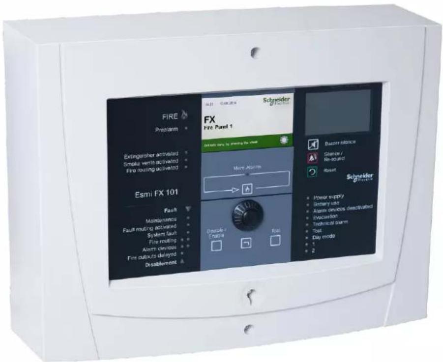
FX101S Sense Fire Detection Panel
Instruction Sheet R10004GB0
Schneider Electric Fire & Security Oy
Sokerilinnantie 11 C
FI-02600 Espoo, Finland
Tel: +358 10 446 511
Website: www.schneider-electric.com
Document number: R10004
Published: 06.03.2019
© 2018 – Schneider Electric. All Rights Reserved. This information is only to be used as guidance. Subject to changes and errors.
Contents
1 FX101S Sense Fire Detection overview ....4
2 FX101S panel external connections....6
1 FX101S Sense Fire Detection overview
FX101S is a powerful one loop fire detection control panel. The full range of Schneider Electric's SLC compatible intelligent detectors can be connected to the system.
Versatile built-in control logic enables easy control of both passive as well as active fire protective equipment and even a three-stage alert and evacuation alarm.
The panel is compatible with other fire detection equipment, such as the FMP Sense Fireman's Panel, zone led panel ZLPX, DAP Sense Delay Alarm Panel, REP Sense Protocol Repeater and MCO Sense Multi Logic Control Unit, as well as alarm management system ESGRAF. The system also provides an interface to the building management system.
| Product | Product code |
| FX101s Sense Fire Detection Panel | FFS00703803 |
Panel installation
The FX101S panel is installed on a surface with the display at a height of approximately 170 cm. The wall has to be strong enough to support the weight of the panel and the batteries.
Connections
See overleaf for general overview of the connections of the FX101S panel.
Cable entries are from behind, from above and from below.
Commissioning and Configuration
The system can be started after the jumper settings are verified. For customer/site specific settings and entry of alarm texts, a PC and licensed software "WinFX3Net" is used. For further information, see the Installation and commissioning manual.
2 FX101S panel external connections
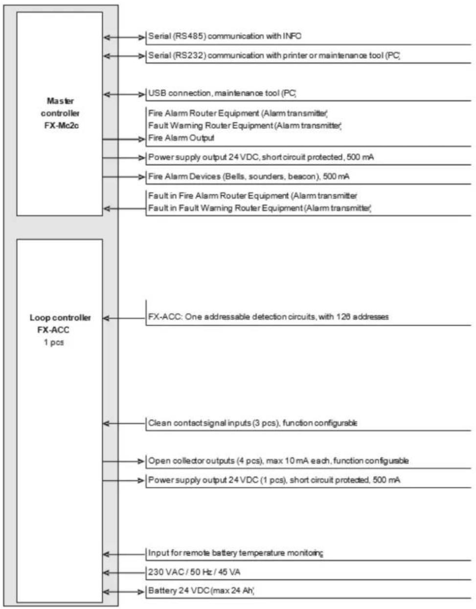
flowchart
graph TD
    A["Master controller FX-Mc2c"] --> B["Serial (RS485) communication with INFO"]
    A --> C["Serial (RS232) communication with printer or maintenance tool (PC)"]
    A --> D["USB connection, maintenance tool (PC)"]
    A --> E["Fire Alarm Router Equipment (Alarm transmitter), Fault Warning Router Equipment (Alarm transmitter), Fire Alarm Output"]
    A --> F["Power supply output 24 VDC, short circuit protected, 500 mA"]
    A --> G["Fire Alarm Devices (Bells, sounders, beacon), 500 mA"]
    A --> H["Fault in Fire Alarm Router Equipment (Alarm transmitter, Fault in Fault Warning Router Equipment (Alarm transmitter)"]
    I["Loop controller FX-ACC 1 pcs"] --> J["FX-ACC: One addressable detection circuits, with 128 addresses"]
    I --> K["Clean contact signal inputs (3 pcs), function configurable"]
    I --> L["Open collector outputs (4 pcs), max 10 mA each, function configurable"]
    I --> M["Power supply output 24 VDC (1 pcs), short circuit protected, 500 mA"]
    I --> N["Input for remote battery temperature monitoring"]
    I --> O["230 VAC / 50 Hz / 45 VA"]
    I --> P["Battery 24 VDC (max 24 Ah)"]
Figure 2. FX101S Sense Fire Detection panel external connections
Note!
The max. 24 V current consumption of the FX101S Sense Fire Detection Panel (SCC-board, loop and all addresses and control panel outputs) is 0,5 A in standby condition and 1,4 A in alarm condition. The standby time required for the system may limit the max. load of the outputs.
Mærke : SCHNEIDER
Model : FX101S
Kategori : Røgalarm