FCPS-24FS8 - Detektor Fire-Lite Alarms - Gratis brugsanvisning og manual
Find enhedens vejledning gratis FCPS-24FS8 Fire-Lite Alarms i PDF-format.

Brugerspørgsmål om FCPS-24FS8 Fire-Lite Alarms
0 spørgsmål om dette apparat. Besvar dem du kender, eller stil dit eget.
Stil et nyt spørgsmål om dette apparat
Download vejledningen til din Detektor i PDF-format gratis! Find din vejledning FCPS-24FS8 - Fire-Lite Alarms og tag din elektroniske enhed tilbage i hånden. På denne side er alle dokumenter nødvendige for brugen af din enhed offentliggjort. FCPS-24FS8 af mærket Fire-Lite Alarms.
BRUGSANVISNING FCPS-24FS8 Fire-Lite Alarms
Firmware Change
This procedure outlines the mechanical installation steps required to install a PROM in the Power Supplies listed in the title block.
Handling precautions for integrated circuits
Static electricity can destroy integrated circuits (ICs)! To prevent damage to the PROM, a wrist strap and a static-free PLCC IC insertion/extraction tool is highly recommended. The manufacturer cannot be responsible for damage to the PROM as a result of improper handling.
System Power Sources
Always remove primary and secondary power before working on the system!
- Disconnect battery backup power before working on the system!
- Proceed by disconnecting AC power to the panel at the main service circuit breaker (not the circuit breaker on the fire control panel's power supply).
- Wait 60 seconds to allow for capacitive discharge before touching any of the system's components.
- Reverse the procedure for powering up the system - AC first, then batteries.
Integrated Circuit Pin Conversion
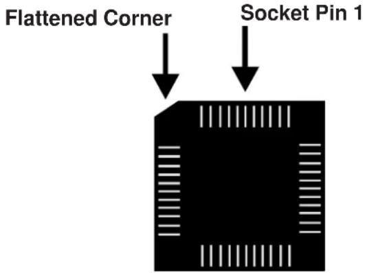
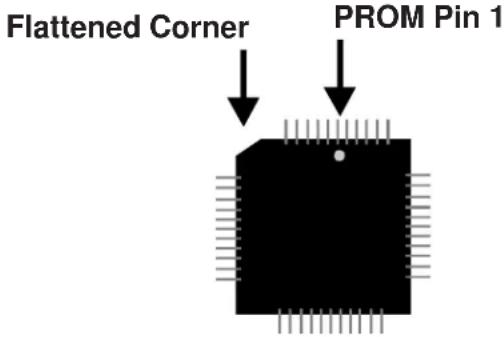
Observe proper orientation of any IC removed or installed! Note location of Pin 1 with respect to the flattened corner and dot on the body of the IC and the relationship to the flattened corner on the IC socket. The replacement PROM must be installed in the same manner as the PROM removed. Failure to observe this orientation will result in destruction of the PROM.
PROM Replacement
Observe proper orientation of any IC removed or installed! To replace the PROM, complete the following steps:
- Remove all power (battery first and then AC) before proceeding with PROM replacement.
- If necessary, disconnect any installed option modules which may inhibit access to PROM.
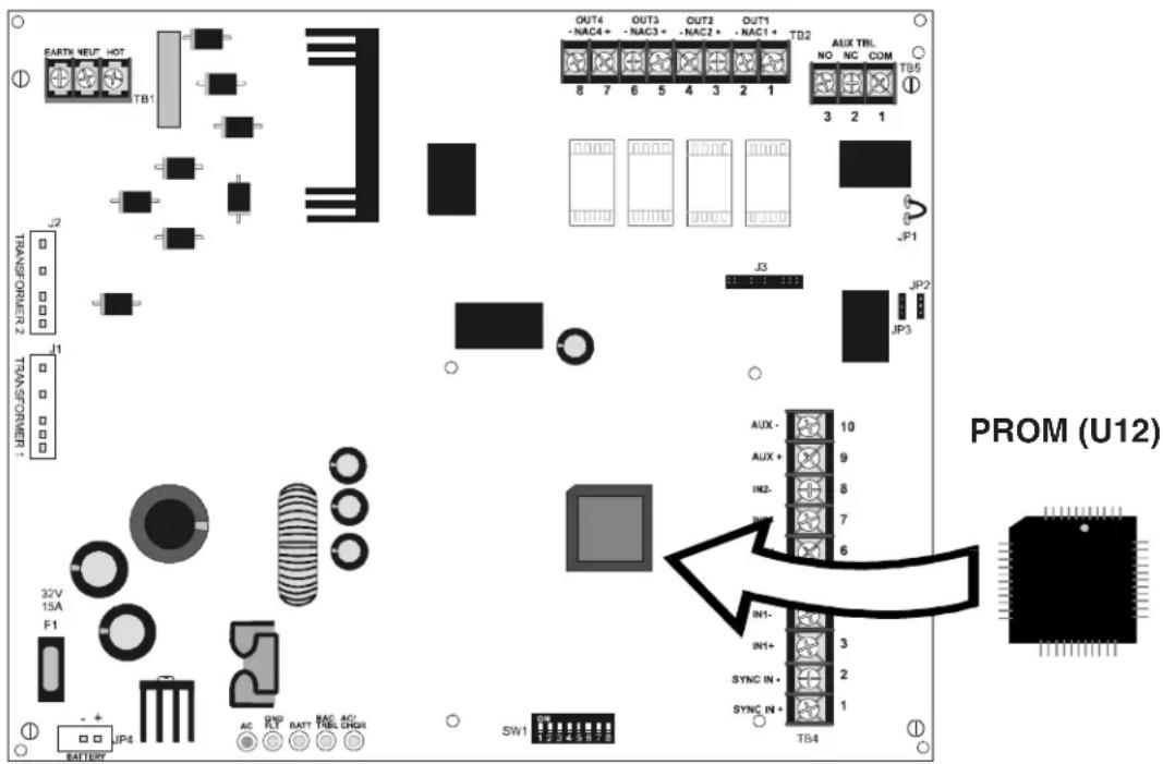
- Locate U12 (center right of the board).
- Gently loosen and remove the PROM from U12.
- Install the replacement PROM in location U12. Observe proper orientation! The dot on the IC should be positioned to the top and the flattened corner of the IC should align with the flattened corner of the socket. Use care to insure that the PROM's pins are not bent or broken during insertion.
- Reconnect any option modules which were removed in Step 2.
- Reconnect power (AC first and then batteries).
Programming and Testing
Test the Power Supply after PROM replacement.
Power Supply Software Changes
The following Table summarizes the Power Supply software changes, specifying these changes by PROM Number and Release Number:
| PROM # | Release # | Summary of Changes |
| 22V42SPCF# | Corrected an issue where the internal trouble contact (TB4 Terminals 3 & 5) would not operate correctly with AC Delay reporting DIP switch (SW1 DIP switch 4) set to the OFF position, during ibAFCAsiSome local AHJs noted that all outputs should respond to an alarm within 10 seconds per UL 864. Software originally had door holder timing set to release after 60 seconds of alarm.This must be changed to 10 seconds.IMPORTANT! This software is ONLY COMPATIBLE with Power Supplies built after Date Code 1506 (i.e. week 15 of year 2006) and with all Export versions and Canadian versions. | |