
VL-W4 - Intercom PANASONIC - Gratis brugsanvisning og manual
Find enhedens vejledning gratis VL-W4 PANASONIC i PDF-format.


Brugerspørgsmål om VL-W4 PANASONIC
0 spørgsmål om dette apparat. Besvar dem du kender, eller stil dit eget.
Stil et nyt spørgsmål om dette apparat
Download vejledningen til din Intercom i PDF-format gratis! Find din vejledning VL-W4 - PANASONIC og tag din elektroniske enhed tilbage i hånden. På denne side er alle dokumenter nødvendige for brugen af din enhed offentliggjort. VL-W4 af mærket PANASONIC.
BRUGSANVISNING VL-W4 PANASONIC
Specifications
| Model number and name | VL-WN1000 (Door Station) | VL-MW1000 (Room Monitor) | |
| Dimensions (ohle mm) |  | 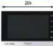 |  |
| Power source | Pak Juss MDC 1F control unit, Class 2 device or Power supply unit 11.6, PS40 - 24°C, 16.4 | Pak Juss MDC control unit, Class 2 device or Power supply unit 3A, PS40 - 24°C, 16.4 | X3C5 |
| Power consumption | Pak Stantery 2.5 V/ Upholding 5.8 W WL PS240: Standley 2.5 W / Upholding 6.5 W | Pak Stantery 2.5 V / Upholding 6.5 W WL PS240: Standley 2.5 W / Upholding 6.5 W | X3C5 |
| Dimensions (in x 2 x 4 x 5) (including pre-cluding machine) | 1 to 100 a 20.5 mm 157.5 to 206.5 a 27.8 mm | 1 to 100 a 20.5 mm 157.5 to 206.5 a 27.8 mm | X3C5 |
| Weight | 293 g | 550 g | |
| Operating environment | Ambient temperature Approx. 10 °C to 35 °C Isolation normally on non-consumer electrical 10% | At least temperature Approx. 0 °C to 40 °C Isolation normally on non-consumer electrical 10% | At least temperature Approx. 0 °C to 40 °C Isolation normally on non-consumer electrical 10% |
| Display | - | To switch the user display in hands screen (D1) or D2 (D3) | - |
| Display language | - | Playman, Mather, French, Indian, German, Spanish, Dutch, Italian and Indonesian | - |
| Linking method | Lattice free | Handy line | - |
| Kewness of lines | 1"000C - 1100000000 - 10" class M/F/000000000 - 1" | 10000000000000000000000000000000000000000000000000000000000000000000000000000000000000000000000000000 | - |
| Hardware platform | T101P, L101 | T101P, L101 | - |
| Hardware | UFS test to be Rainer | UFS test to be Rainer | - |
| Card reader, RF ID | 1360 W/ 162000, 14443 Type A 040481 | - | |
| Expanded link flow | E. coli E.1. Relay, new VL-FL* is required until appropriate to | Sensor: Insurc 2: Isrrating emergency / emergency buttons | - |
| Switching units | Interrating Appone, T101*, Verically Appone, RF* | - | |
| Upgrade sensor | 1.5V/ 2.5mA CM/ 5mm | - | |
| Minimum luminescence required | I. by within account, 55 cm from the camera lens | - | |
| Lighting method | White coloured LLD lights | - | |
| Wave / Audio format | Power II 2841, Audio, S/11 | Power II 2841, Audio, S/11 | - |
| Recording | - | Internal rotary window with clockwise axis sensors | - |
| Facing (IC rating) | IPSE - / - | - | |
| Initiation method | Gas force mounted mounting boxes supplied | Surface must mounting blocks supported or Iach's motor: Current box, IL, AKI-250 solid separately | - |
| External material | PC-AAS more | PC-AAS more | - |
| Supportive functions | • Lighting and voltage ranges on the IEC / Current measurement • Thrift battery laser | • Lighting and voltage ranges on the IEC • Frequency, ceiling wall, Sensor, Door panel • Interconnect side between main components for air pollutants and refrigerants • Cable to SP Wireless guard circuit connection, etc. • Fager press up to 52 IP cameras per meter • Signal press up to 52 IP cameras per meter | - |
- (2) PSS40 is said separately. "2 Water resistance is only used for the door stall is installed correctly, according to the instructions in the Operating instructions, and appropriate water protection measures are taken
| Modul number and name VL-W1800 (Control Box) Options | |||
| Dimensions (kilu mm) | 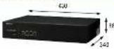 | VL. PS | Rt. RL31 (Mdy 2x6) |
 |  | ||
| Power source | 100-240 V DC, 0.85A-0.9, 50Hz | Input: 220-250 V DC, 0.2 x 3000 Hz Output: 470 V DC, 2Hz | Supplied by the door system |
| Power consumption | Under 50 °C | _ | |
| Dimensions (ft x W x 2 ft) (Excluding including sections) | 30 x 500 x 500 mm 110 x 100 x 54 mm 92 x 90 x 28 mm | ||
| Watts | 4.5 kg 250 g 50 g | ||
| Operating orientation | Antibond temperature above 0.75 to -40 °C For each direction is non-coholders up to 50 % | Antibond temperature above 0.75 to -50 °C After a slight cooling angle of 90°/°C/moseter | Antibond temperature above 0.75 to -40 °C Before a slight cooling angle up to 50 % |
| Relatives interface | CBASE-T/CIBASE-T/O-DIGBASE-T Units/DIVI/UX-X | ||
| Relatives printer | TCP/IP, UFP | ||
| Wing | U-P, U-S, U-G, U-H | ||
| Installation method | Planned to 15-inch middle width section or offset to RM unit | Well mounted in each of RM unit | |
| Current minute | Pent Cells, 45% Lower Upper Colloids, 30s | Fears mounted in PC-EBS units | Phone mounted ABS unit |
| Support functions | ● Make Bracket ● Wake slot ● Use not verification ● Supports up to 2000 SIP devices (untested SIP server) | ||
Trademark
NPEE is a significant outlook of RSP BX, and a bad risk estimate.
Phone and Mail are based on Apple Inc. (Igex) for the U.S. and of our own
Nordia, a lot of money of 2009, LLC.
- The software of the product is based in part on the work of the Independent IFRS Group.
- All other characteristics centered herein are the property of the respective owners
Important
- Sales: Distribution, currently was the company distribution and that also stated being using the overall
- Paracase cannot be responsible for the performance of the network and other other manufactures and products used on the market.
The option is not assigned to provisions come from property taxes. To the risk
Paraservice that is not responsible for any damage or loss, as a result of processing loss.
When being using the product, please then to consider for the right of others with regard in privacy and rights of personal
- The actual protection may fully implement
- 水化物的物质的反应
• Design and Specification are subject to change other works
• These products may be subject to export bonds, regulators.
DISTRIBUTED BY
Panasonic
[Unreadable due to severe distortion and noise]
Panasonic
IP Video Intercom System for Apartment complexes
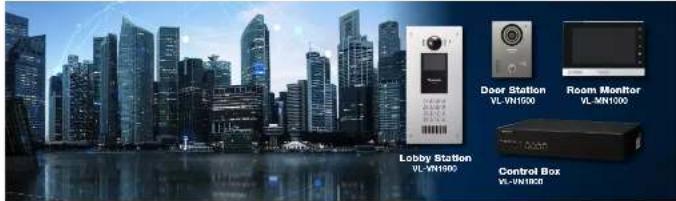
Key Features
Full IP system
A pure IP system
The Door Station and Room Monitor support PoE (IEEE 002.3at compliant)
Supports large apartment systems
supports large apartment systems
Up to 200 SIP devices on a system without a Control Box
Up to 2,000 S&P services of a system with a Control Box
Up to 12,000 eF devices on a system up to a control box at
Easy installation, convenient maintenance
Easy Setup includes set-up tool (or mass configuration of large numbers of
devices
Mobile Remote ^1
Bemora visitor answering while coaching visitor's live image
Руш погреле иод кирота и поле
Historic ice in chat room
Sensor notification
Allow visitors to enter the baby and lift
Others
5.2.10
E-mail Notification (Control Box required)
voice mail (control box required)
Visitor Recording
Lith Insgainer: Third party device acquired
| Model number and name | VL-VMI1900 (Lobby Station) | ||
| Dimension(Unit mm) | 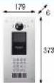 | 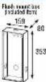 | VL-PS243 (Phase Supply Unit) |
| Power source | Power supply and DL-PS243, 16.25/20.14°C/40, 0.2A-AUDOS-Est, Output 28-10V, U.S.A | Image sensor | 2.4 M phase 10000 sensor |
| Minimum Remittance required | 1.6 in the above package, 50 cm from first camera lens | ||
| Lighting medium | White aluminum (100 psi) | ||
| Power consumption | Shareby 1.5 W, Operating 8.5 W | IP rating /UK rating | PSS - Completed on 1002 |
| Dimensions (in mm x 1x 1x 1x 1x 1x 1x 1x 1x 1x 1x 1x 1x 1x 1x 1x 1x 1x 1x 1x 1x 1x 1x 1x 1x 1x 1x 1x 1x 1x 1x 1x 1x 1x 1x | 321x 179x 0 for (excluding one line selected into the wall) | IP rating /UK rating | VL-PLS243 - Peak impact measure must be supplied |
| Weight | 16.25/20.14°C, 1.5 KgXL-PS243, 2.5 Kg | Installation medium | VL-PLS243 - Load model of load to 100 gm |
| Operating environment | 16.25/2014E, Ambient temperature Approx. = 12 °C to = 50 °C, output turned by, from connected, to 100 % XL-PS243, 2.5K, 100% output. Approx. 40% to 50 % XL-PS243 turned by, from connected, to 100 % XL-PS243 turned by, from connected, to 100 % XL-PS243 turned by, from connected, to 100 % XL-PS243 turned by, from connected, to 100 % XL-PS243 turned by, from connected, to 100 % XL-PS243 turned by, from connected, to 100 % XL-PS243 turned | ||
| Display | 3.5 inch colour size (200x400 x 400) | Wiring | UDP (just be unsigned) |
| Display language | Largest, Arabic, French, Italian, German, Korean, Dutch, 16.25/20.14°C, 1.5 Kg, 1.5 Kg, 1.5 Kg, 1.5 Kg, 1.5 Kg, 1.5 Kg, 1.5 Kg, 1.5 Kg, 1.5 Kg, 1.5 Kg, 1.5 Kg, 1.5 Kg, 1.5 Kg, 1.5 Kg, 1.5 Kg, 1.5 Kg, 1.5 Kg, 15.25/20.14°C, 1.5 Kg, 1.5 Kg, 1.5 Kg, 1.5 Kg, 1.5 Kg, 1.5 Kg, 1.5 Kg, 1.5 Kg, 1.5 Kg, 1.5 Kg, 1.5 Kg, 1.5 Kg, 1.5 Kg, 1.5 Kg, 1.5K | SP rating | Recommended SP rating up to 10000 ms |
| Video / Audio format | Video - 100 Hz, duration = 7711 | ||
| Timing method | Fixed time | Connected information | Support for active lock-releasing performance locking up to 1 |
| Timing angle | Temperature, Angle, 120°, Vertical, Absolute, 12°, 12°, 12°, 12°, 12°, 12°, 12°, 12°, 12°, 12°, 12°, 12°, 12°, 12°, 12°, 12°, 12°, 12°, 12°, 12°, 12. | Supervised function | • Design a DVP line with the last frame (200x200 x 200 ms)• Lower main lines using filters (the same, each line is)• Lower main lines (both lines are not used)• Insert detection buffer• Use case by wire or a PM code or RPE calls (M/F450)• Reception engine (set for calls are checked to be understood)• Receiving images of pictures of RPE• Cell integration? |
| Card mode (RFD) | 13.5K (60000000000000000000000000000000000000000000000000000000000000000000000000000000000000000000000000000 | ||
1 Control Box (DL-741 500) requires. Compare mobile devices. Phone tx and later, Fox 4x and later iOS 3x and later Android ^™ devices (Januar 4.4 and late), as of June 2010. Some mobile devices
may not be compatible. Supported languages: English, Vietnamese and Indonesian
2. A linkarity is important for the problem of the condition of the same time. For more than 10 minutes, it is also a small positive value.
13. Water reservoirs in bulk areas of the middle station to install concrete connection to the intermediate level of installation for a water reservoir, and commercial water construction requires are based
System Diagram of the IP Apartment System
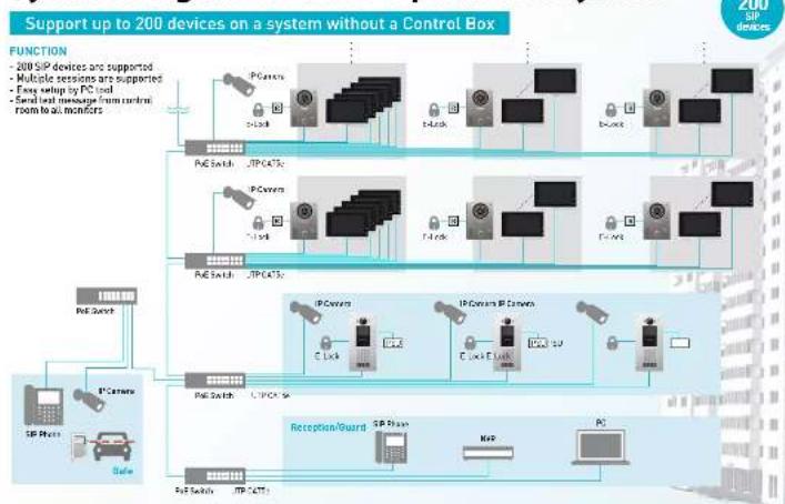
flowchart
graph TD
    A["200 SIP devices supported"] --> B["Multiple sessions are supported"]
    B --> C["Easy setup by PC load"]
    C --> D["Serial load message from control"]
    D --> E["From local controllers"]
    A --> F["PC Camera"]
    F --> G["IP Switch"]
    G --> H["IP Subnets"]
    H --> I["IP Camera"]
    I --> J["IP Switch"]
    J --> K["IP Subnets"]
    K --> L["IP Camera"]
    L --> M["IP Switch"]
    M --> N["IP Subnets"]
    N --> O["IP Camera"]
    O --> P["IP Switch"]
    P --> Q["IP Subnets"]
    Q --> R["IP Camera"]
    R --> S["IP Switch"]
    S --> T["IP Subnets"]
    T --> U["IP Camera"]
    U --> V["IP Switch"]
    V --> W["IP Subnets"]
    W --> X["IP Camera"]
    X --> Y["IP Switch"]
    Y --> Z["IP Subnets"]
    Z --> AA["IP Camera"]
    AA --> AB["IP Switch"]
    AB --> AC["IP Subnets"]
    AC --> AD["IP Camera"]
    AD --> AE["IP Switch"]
    AE --> AF["IP Subnets"]
    AF --> AG["IP Camera"]
    AG --> AH["IP Switch"]
    AH --> AI["IP Subnets"]
    AI --> AJ["IP Camera"]
    AJ --> AK["IP Switch"]
    AK --> AL["IP Subnets"]
    AL --> AM["IP Camera"]
    AM --> AN["IP Switch"]
    AN --> AO["IP Subnets"]
    AO --> AP["IP Camera"]
    AP --> AQ["IP Switch"]
    AQ --> AR["IP Subnets"]
    AR --> AS["IP Camera"]
    AS --> AT["IP Switch"]
    AT --> AU["IP Subnets"]
    AU --> AV["IP Camera"]
    AV --> AW["IP Switch"]
    AW --> AX["IP Subnets"]
    AX --> AY["IP Camera"]
    AY --> AZ["IP Switch"]
    AZ --> BA["IP Subnets"]
    BA --> BB["IP Camera"]
    BB --> BC["IP Switch"]
    BC --> BD["IP Subnets"]
    BD --> BE["IP Camera"]
    BE --> BF["IP Switch"]
    BF --> BG["IP Subnets"]
    BG --> BH["IP Camera"]
    BH --> BI["IP Switch"]
    BI --> BJ["IP Subnets"]
    BJ --> BK["IP Camera"]
    BK --> BL["IP Switch"]
    BL --> BM["IP Subnets"]
    BM --> BN["IP Camera"]
    BN --> BO["IP Switch"]
    BO --> BP["IP Subnets"]
    BP --> BQ["IP Camera"]
    BQ --> BR["IP Switch"]
    BR --> BS["IP Subnets"]
    BS --> BT["IP Camera"]
    BT --> BU["IP Switch"]
    BU --> BV["IP Subnets"]
    BV --> BW["IP Camera"]
    BW --> BX["IP Switch"]
    BX --> BY["IP Subnets"]
    BY --> BZ["IP Camera"]
    BZ --> CA["IP Switch"]
    CA --> CB["IP Subnets"]
    CB --> CC["IP Camera"]
    CC --> CD["IP Switch"]
    CD --> CE["IP Subnets"]
    CE --> CF["IP Camera"]
    CF --> CG["IP Switch"]
    CG --> CH["IP Subnets"]
    CH --> CI["IP Camera"]
    CI --> CJ["IP Switch"]
    CJ --> CK["IP Subnets"]
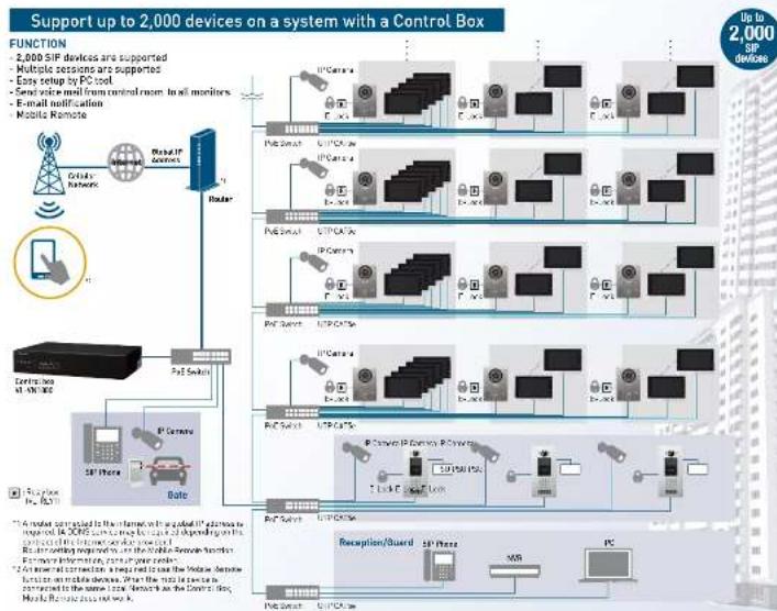
flowchart
graph TD
    A["Mobile Remote"] --> B["PC Server"]
    B --> C["IP Center"]
    C --> D["PC Switch"]
    D --> E["Control Unit AMOS"]
    E --> F["Data Bus"]
    F --> G["IP Server"]
    G --> H["PC Switch"]
    H --> I["IP Center"]
    I --> J["PC Switch"]
    J --> K["IP Center"]
    K --> L["PC Switch"]
    L --> M["IP Center"]
    M --> N["PC Switch"]
    N --> O["IP Center"]
    O --> P["PC Switch"]
    P --> Q["IP Center"]
    Q --> R["PC Switch"]
    R --> S["IP Center"]
    S --> T["PC Switch"]
    T --> U["IP Center"]
    U --> V["PC Switch"]
    V --> W["IP Center"]
    W --> X["PC Switch"]
    X --> Y["IP Center"]
    Y --> Z["PC Switch"]
    Z --> AA["IP Center"]
    AA --> AB["PC Switch"]
    AB --> AC["IP Center"]
    AC --> AD["PC Switch"]
    AD --> AE["IP Center"]
    AE --> AF["PC Switch"]
    AF --> AG["IP Center"]
    AG --> AH["PC Switch"]
    AH --> AI["IP Center"]
    AI --> AJ["PC Switch"]
    AJ --> AK["IP Center"]
    AK --> AL["PC Switch"]
    AL --> AM["IP Center"]
    AM --> AN["PC Switch"]
    AN --> AO["IP Center"]
    AO --> AP["PC Switch"]
    AP --> AQ["IP Center"]
    AQ --> AR["PC Switch"]
    AR --> AS["IP Center"]
    AS --> AT["PC Switch"]
    AT --> AU["IP Center"]
    AU --> AV["PC Switch"]
    AV --> AW["IP Center"]
    AW --> AX["PC Switch"]
    AX --> AY["IP Center"]
    AY --> AZ["PC Switch"]
    AZ --> BA["IP Center"]
    BA --> BB["PC Switch"]
    BB --> BC["IP Center"]
    BC --> BD["PC Switch"]
    BD --> BE["IP Center"]
    BE --> BF["PC Switch"]
    BF --> BG["IP Center"]
    BG --> BH["PC Switch"]
    BH --> BI["IP Center"]
    BI --> BJ["PC Switch"]
    BJ --> BK["IP Center"]
    BK --> BL["PC Switch"]
    BL --> BM["IP Center"]
    BM --> BN["PC Switch"]
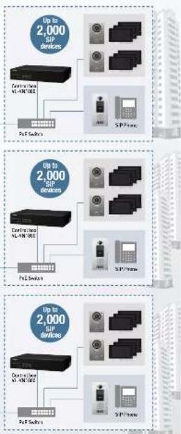
Support up to 10,000 devices on a system with 5 Control Boxes
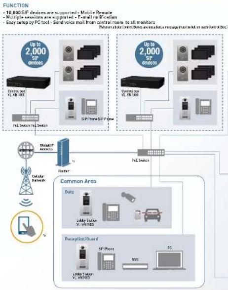
flowchart
graph TD
    A["10,000 SIP devices are supported - Mobile Remote\nMultiple sessions are supported - E-mail notification\nEasy setup by PC tool - Sand voice mail from control room to all mobiliators\nReson data center from external data management or Max antenna file"] --> B["Router"]
    B --> C["Local Network"]
    C --> D["Common Area"]
    D --> E["Gate"]
    D --> F["Lobby Station V-3V1022"]
    D --> G["Retapition/Guard"]
    E --> H["SP Phone"]
    F --> I["Lobby Station V-3V1023"]
    G --> J["NS"]
    H --> K["Router"]
    I --> K
    J --> K
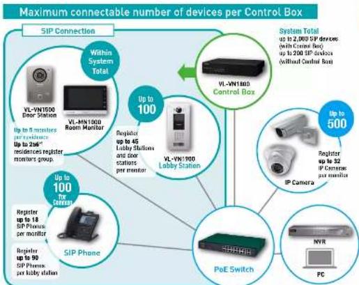
flowchart
graph TD
    A["Up to 100"] --> B["Within System Total"]
    B --> C["VL-VN1500 Door Station"]
    B --> D["VL-VN1500 Room Monitor"]
    B --> E["Up to 10 monitors per monitor"]
    B --> F["Up to 26" residences register monitors group."]
    B --> G["Register up to 45 Lobby Stations and door stations per monitor"]
    B --> H["Up to 100 for Carrier"]
    B --> I["Register up to 90 SIP Phrases per monitor"]
    B --> J["Register up to 18 SIP Phrases per monitor"]
    B --> K["Register up to 90 SIP Phrases per lobby station"]
    L["Up to 500"] --> M["VI-VN1500 Control Box"]
    M --> N["VL-VN1500 Lobby Station"]
    M --> O["Register up to 32 IP Cameras per monitor"]
    P["SIP Phone"] --> Q["PoE Switch"]
    Q --> R["NVR"]
    Q --> S["PC"]
Maximum connectable number of monitors per Residence
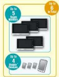
"Commutative methods. Phone to and law, Paid by online iOS 12 and 13/14/15 devices
Bed, old and least as of June 27, 2013
In the case of the following:
can be sourced as 150 ^nd devices.
17.08.28 to see the Nettler remote app of your mobile devices and video apps are then able.
Control Box through the 2017
For interest on you now looking to help them
support@100%
Mærke : PANASONIC
Model : VL-W4
Kategori : Intercom