
85745283 - Fjernsyn HAGER - Gratis brugsanvisning og manual
Find enhedens vejledning gratis 85745283 HAGER i PDF-format.


Brugerspørgsmål om 85745283 HAGER
0 spørgsmål om dette apparat. Besvar dem du kender, eller stil dit eget.
Stil et nyt spørgsmål om dette apparat
Download vejledningen til din Fjernsyn i PDF-format gratis! Find din vejledning 85745283 - HAGER og tag din elektroniske enhed tilbage i hånden. På denne side er alle dokumenter nødvendige for brugen af din enhed offentliggjort. 85745283 af mærket HAGER.
BRUGSANVISNING 85745283 HAGER
KNX Radio timer quicklink
Safety instructions
Electrical equipment must only be installed and assembled by a qualified electrician in accordance with the relevant installation standards, regulations, directives and safety and accident prevention directives of the country.
Failure to comply with these installation instructions may result in damage to the device, fire or other hazards.
The radio transmission is not suitable for safety or alarm applications.
These instructions are an integral component of the product, and must be retained by the
end user.
Design of the device
(2) (1)

Figure 1: Design of the device
(1) Insert (see Accessories, not in scope of delivery)
(2) Frame (not in scope of delivery)
(3) Application module
(4) Display
(5) Design
(6) Screw for dismantling protection (not for
design lines R.1/R.3
(7) Open
Function
This device is a product of the quicklink system, in which installation devices communicate via radio signals.
quicklink stands for a configuration mode in which the function-related connection between transmitters and receivers is set on the device through push-buttons and displays without further tools. All devices configurable by quicklink can be operated together in one system.
This device is compliant to the R&TTE-Directive 1999/5/EG. The Declaration of Conformity and further system information can be found on our homepage www.berker.de.
The device may be used in all EU and EFTA
countries
Correct use
- Application module for relay switch insert or power supply for radio application modules - Manual, time-controlled or automatic switching of the connected loads
- Transmission and reception of manual, time-controlled and automatic operation commands via quicklink
- Only suitable for use in indoor areas, no drip or spray water
Product characteristics
- quicklink functions for inclusion in the remote and group control of lighting - Integration into scenes - Two preset standard time programmes
- Individual adjustment of the time programmes possible
- Astro programme for automatic operation at dawn/dusk
- Astro time shift to adjust the switching times - Holiday programme for random switching times in automatic mode
- Party programme to avoid unintentional switching operations through automated switching commands as well as radio/extension commands - Keylock
- Automatic switching to standard/daylight saving time - Brightness-dependent switching when using a
Performance after mains breakdown/return of mains supply
- Main's breakdown: Saving of the current configuration and programming in the non-volatile memory. The device then switches to economy mode. Only the internal clock continues to run to keep the time up-to-date. The use of a buffer memory ensures that the time stays up-to-date for up to 24 hours.
- Return of mains supply: The application module executes an initial on operation ^1 , the basic display is restored. The saved configuration and programming is loaded from the memory. Any operations per
ding when the power supply broke down will not be executed after return of mains supply. If the buffer memory is full, date and time must be entered again.
Operation
Operating concept and display elements
A short press on the on and off buttons (Figure 2) switches loads manually, whilst a press >2 seconds can trigger various functions within the menu operation.
The current clock status is displayed. Active functions are displayed by using symbols (Table 1). Display illumination is activated for as soon as a button is pressed.

Figure 2: Display and operating elements
(8) on button (9) Back button (10) OK button (11) off button (12) Display of weekday and time (13) Display of the active function/programming (14) Display of next switching times
| Symbol function | |
| Keylock active | |
| Manual operation,no automatic switching times | |
| P1 P2 Presel programme P1 (week programme) or P2 (week/weekend programme) is active | |
| Astro programme is active,switching times are controlled depending on dawn/dusk times | |
| Party programme is active,manual operation only. Programmes,extension units and radio commands are not executed | |
| Normal radio operation is active,radio commands for master or group controls can be transmitted and received | |
| Stand-alone operation,Device has temporarily been removed from higher-level master controls, but can still be active as a group control. | |
Table 1: Symbols in the function/programme line (13) of the display
Switching - operation from the basic display Manual operation of the controlled loads is possible at any time from the basic display, even if
■ Press the on button. Load switches ON. ■ Press the off button. Load switches OFF.
Locking/unlocking operation The operation buttons of the time switch can be locked, in order to prevent unintentional operation e.g. by children.
The time switch is in the basic display. ■ Press the ← button for more than 5 seconds.
■ is displayed. The operation buttons are locked. ■ Press the ← button again for more than 5 seconds.
disappears in the display. The operation buttons are enabled.
Opening the menu and navigating The device is set and programmed via the menu. (15)

17)
Main menu
(15) Selected menu item (16) Position display of the selected menu item in the list of options
(17) Next option in the list ■ Short press on any button. Operation is activated. The display is illuminated.
■ Press the OK button for more than 2 seconds.
The main menu is displayed. The first menu item Auto/Manual operation (Fig. 3, 15) is
highlighted dark.
■ Press the on (↑) or off (↓) button to navigate through the menu.
The selected menu item is highlighted dark.
■ Confirm the selected option by pressing OK.
The submenu opens. Navigation through the menus can continue as
described above.
■ Press the ← button. The display switches to the previous contents. To return to the basic display, press the ← button multiple times as necessary.
If no button is pressed for a period of two minutes, the display returns to the basic display.
Figure 4 shows an overview of the functions in the menus/submenus: A.. for the user and E.. for the electrician refer to sections for additional information. Menu items in brackets are visible depending on the timer programming status.
Setting the values Values, such as time or date, have to be set first for the programming of same functions. The value to be set is of selected and is highlighted dark. ■ Press the on (1) or off (1) button. Short press on button. Change the value by one slip. Keep button pressed: Scroll through values. Scrolling stops when the button is released. Setting-Sensing (28) If switching times are set, then a symbol (28) shows whether it is an ON or OFF switching time. ■ Press the OK button. The set value is applied. ■ Press the ◆◆◆◆◆ The display switches to the previous value. The setting is not applied. Submenu A1 - Select programme One can choose between the following programmes: Manual operation: Operation takes place solely using the buttons (see Switching - operation from the basic dis

flowchart
graph TD
    A["Manual operation"] --> B["system mode"]
    B --> C{(18)}
    C --> D["system mode"]
    D --> E{(19)}
    E --> F["system mode"]
    F --> G{(20)}
    G --> H["system mode"]
    H --> I{(21)}
    I --> J["system mode"]
    J --> K{(22)}
    K --> L["system mode"]
    L --> M{(23)}
    M --> N["system mode"]
    N --> O["system mode"]
    O --> P{(24)}
    P --> Q["system mode"]
    Q --> R{(25)}
    R --> S["system mode"]
    S --> T{(26)}
    T --> U["system mode"]
    U --> V{(27)}
    V --> W["system mode"]
    W --> X{(28)}
    X --> Y["system mode"]
Figure 4: Menu overview
- Time programmes P1: 7 - 21 h and P2: 7 - 21 h + 8 - 22 h
These programmes are factory preset but can
be changed individually. P1 is a week programme with identical swit-
ching times for each day, P2 is a week/week-end programme with different switching times.
end programme with different matching times for Mon. - Fri. and Sat. - Sun.
- Astro programme: Programme for down/dark-dependent control
Programme for cashflow-dependent control of the loads (see submenu A7 - Setup Astro
programme). The Active programme in only displayed if it
The Asaro programme is only displayed if it has been set up.
- Party:
The Party function prevents unintentional switching of the connected loads by programmed
switching times or extension unit operation, e.g. switching ratio lighting OFF during a barbecue
When the Party programme is active, a load
can only be operated manually using the but-
tons on the time switch. Control via high-level control-sections and sensors as well as by ex-
tension units, radio and forced control commands is deactivated.
If the load is moved to a defined state in force, made (see Table 4) and this forced mode is
mode (see Table 4) and this forced mode is active, then the Party programme cannot be
selected and the following message appears in the display: Party programme not available
in forced mode
The device shows the Programme selection ubmenu (Fig. 4, 18). The most recently selected
programme is highlighted dark.

(1) 1-2017年1月1日
■ Press on (1) or off (4) button to select the desired programme.
■ Press the OK button
The screen switches to the basic display. The
selected programme is run, the corresponding symbol (Table 1) is shown in the display (Fig.
2, 13).
Submenu A2 - Change, delete or add to
programmes
The options modify and restore defaults (Figure 2, 22) can be used for the preset factory pro-
grammes:
- modify to adapt, add to or delete operation times. A maximum of 20 operation times per
day are possible.
- restore defaults to reset a modified programme to the factory default programming.
Switching times can only be edited individually
under modify. It is not possible to edit pro-gramme blocks (e.g. Mon - Fri).
- Gramine Blocks (e.g. Wall: -1 ft.). - Press the on or off button to select options or
to change the values.
■ Press the OK button
Short press on button: Confirmation of the current selection as the set value.
Current selection of the set value. Long press on button (≥ 2 s) in programme ed
Long press on button (1-2) in program setting: Adding an extra switching time or deletion

■ Press the ← button
Short press on button: The display switches to the last content.
Long press on button (> 2 s): Programming is completed, the switching times are ignored.
completed, the switching times are skipped. Changes can be saved or rejected.


switching times are missing. Saving is nevertheless possible

[Non-Text]
Submenu A3 - Activating/deactivating Holiday
programme The Holiday programme is a simple form of the
The Holiday programme is a simple form of the presence simulation. The switching times of an
existing programme (P1, P2, Astro) are varied, randomly, by ± 15 minutes. If switching times are
too close together (difference < 15 minutes), then they are not varied.
They are not valued. The time switch can be found in the submenu
Holiday programme (Fig. 4, 20)
■ Confirm activation with OK. The screen switches to the basic display and
the symbol 📁 for Holiday programme is
displayed (Fig. 2, 13).
■
The screen switches to the basi
the symbol 📁 for Holiday programme is
hidden in the display.
ubmenu A4 - Activating/deactivating Stand-
alone programme The Stand-alone programme can be used for
The Stand-alone programme can be used for radio installations, in which the time switch was
assigned to a master controller as a subordinate controller. In Stand-alone operation the device
ignores the radio commands of higher-level mast controls and forced control commands, as well as
controls and forced control commands, as well as extension unit signals, i.e. operation commands
concerning the local load are not executed. ④ If the load is moved to a defined position is
1 In the load is moved to a defined position in forced mode (see Table 4) and this forced m
de is active, then the Stand-alone programme cannot be selected. The following message
appears in the display: Stand-alone pro-
The timer can be found in the submenu Stand-
alone programme (Fig. 4, 21).
■ Confirm activation with OK. The screen switches to the basic display and
the symbol (1+4) for Stand-alone programme
is displayed (Fig. 2, 13).
■
The screen switches to the basi
the symbol ◆ for normal radio operation is displayed (Fig. 2-43).
is displayed (Fig. 2, 13).
Submenu A5 - Set time/date
In the main menu (Fig. 4, 18), Timevdate is highlighted dark.
■ Short press on OK button.
The hour display as an active element is high-lighted desk.
■ Set the date and time (see Setting values).
When all the setting options have been run
Operation and installation instructions
Installation Instructions

KNX radio timer quicklink
Order-No. 8574 52
GB
Submenu A6 - Set time options
can be activated or deactivated for the timer. The submenu Time setting is displayed (Fig. 4)
The subfield time setting is displayed (Fig. 425).
■

■ Press the buttons on or off to select the re-
quired setting and confirm by pressing OK. The device applies the setting and returns to
the submenu Time setting.
Submenu A7 - Setup Astro programme
The Astro function causes controlled loads to be switched at dawn and dusk, meaning that the
switched at dawn and dusk, meaning that the switching times are adjusted automatically accor-
ding to the season. One can choose ON or OFF switching operations for dawn and dusk. As these
switching times can be very early or very late, the Astro function offers enhanced options in order to
ada
- Deviation from dawn time by ± 120 minutes
- Deviation from dusk time by ± 120 minutes - Earliest ON/OFF switching time (Earliest O
OFF at) No switching times are awarded before the
No switching times are executed before the earliest ON/OFF switching time, as defined by
dawn. The lighting is switched off at the set time. Later Astro switching times are executed
normally
Example
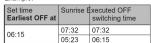
- Latest ON/OFF switching time (Latest ON/OFF
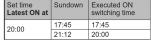
at) No switching times are executed after the latest
ON/OFF switching time, as defined by dusk. The lighting is switched on at the set time. Ear
lier Astro switching times are executed normal
By. Evomale
Outfall
The installation location must be set to determine the correct future times.
the correct Astro times.
- Country fruity selection. Simple setting option by selecting a country
and a city near the location from a comprehensive list of European cities.
- The setting is made by entering the geograf
co-ordinates and time zone of the location. If the location is outside, Evans or a high level
If the location is outside Europe of a high level of accuracy is required for the Astro times, then
the setting should be made using the co-ordi-pates.
。
[Non-Text]
[Non-Text]
[Non-Text]
[Non-Text]
[Non-Text]
[Non-Text]
[Non-Text]
[Non-Text]
[Non-Text]
[Non-Text]
[Non-Text]
[Non-Text]
[Non-Text]
[Non-Text]
[Non-Text]
[Non-Text]
[Non-Text]
[Non-Text]
[Non-Text]
[Non-Text]
[Non-Text]
[Non-Text]
[Non-Text]
[Non-Text]
[Non-Text]
[Non-Text]
[Non-Text]
[Non-Text]
[Non-Text]
[Non-Text]
[Non-Text]
[Non-Text]
[Non-Text]
[Non-Text]
[Non-Text]
[Non-Text]
[Non-Text]
[Non-Text]
[Non-Text]
[Non-Text]
[Non-Text]
[Non-Text]
[Non-Text]
[Non-Text]
[Non-Text]
[Non-Text]
[Non-Text]
[Non-Text]
[Non-Text]
[Non-Text]
[Non-Text]
[Non-Text]
[Non-Text]
[Non-Text]
[Non-Text]
[Non-Text]
[Non-Text]
[Non-Text]
[Non-Text]
[Non-Text]
[Non-Text]
[Non-Text]
[Non-Text]
[Non-Text]
[Non-Text]
[Non-Text]
[Non-Text]
[Non-Text]
[Non-Text]
[Non-Text]
[Non-Text]
[Non-Text]
[Non-Text]
[Non-Text]
[Non-Text]
[Non-Text]
[Non-Text]
[Non-Text]
[Non-Text]
[Non-Text]
[Non-Text]
[Non-Text]
[Non-Text]
[Non-Text]
[Non-Text]
[Non-Text]
[Non-Text]
[Non-Text]
[Non-Text]
[Non-Text]
[Non-Text]
[Non-Text]
[Non-Text]
[Non-Text]
[Non-Text]
[Non-Text]
The submenu Astro setting is displayed (Fig. 4, 26).
■ Use the buttons on or off to select the setting type and confirm by pressing OK. The country/city selection and the co-ordinate settings are displayed.
■ Set the location and times (see Setting values) Run through all the setting options. Having confirmed the Latest ON/OFF at? time

■ Press the buttons on or off to select the required option and confirm by pressing OK. Yes: The screen switches to the basic display. The Astro programme is run and the appropriate symbol (Table 1) displayed (Figure 2, 13). The Astro settings are saved and Astro is added to the programme selection (Fig. 4, 19). No: The screen switches to the basic display. The Astro settings are saved and Astro is added to the programme selection (Fig. 4, 19), but is not run.
Submenu A8 - Set display contrast
In the submenu Basic setting (Fig. 4, 23), Display setting is highlighted dark. ■ Short press on OK button. The current contrast value as an active element is highlighted dark.

■ Set the contrast (see Setting values). Having made the setting, the display returns to the Basic setting submenu.
Submenu A9 - Resetting the device to the factory settings In the factory setting, both the user's settings, such as programmes or Astro settings, are reset and all the configured radio logic function deleted.
In the submenu Basic setting, Factory setting is highlighted dark.
■ Press the OK button for more than 10 seconds During initialisation, the display shows ◎ and then switches to Start-up mode. Language, time and date must be reset.
Information for electricians
Installation
Selecting installation location
A minimum distance between the transmitter and corresponding receiver of about 1 m must be maintained.
A minimum distance to electronic devices which emit high frequency signals such as computers, electronic transformers or microwave devices of approx. 0.5 m must be maintained.
Mounting on or close to metal surfaces may cause impairment of the radio transmission. Take material penetration into account. The range
of the system can be optimised by selecting the best possible mounting location:
1.2
| Material Degree of material penetration | |
| Wood, plaster, plasterboard, uncoated glass | approx. 90 % |
| Brick, press boards approx. | 70 % |
| Reinforced concrete, fl oor heating | approx. 30 % |
| Metal, metal grids, aluminium laminates, coated glass | approx. 10 % |
| Rain, snow approx. 1 ... 40 % | |
Table 2: Material penetrati
Assembly of the device (Figure 1)
The insert is installed (see operating instructions for the insert).
for the insert). Attach the application module (3) together with
Attach the application module (5) together with frame (2) to a suitable insert (1) so that the contact pins are inserted into the available jack. As soon as voltage is supplied to the application module, the display indicates whether the application module and the insert are compatible with each other:
| Display text Meaning | |
| (Operating mode indicator) | Compatible |
| Invalid Power Module | Not compatible |
| Invalid or defective Power Module! | Incompatible or missing supply voltage. Check the insert and replace as necessary. |
| Changed Power Module / Reset to factory? | Compatible, but not confi gu red to each other. |
| Direct reset of the radio confi guration to the factory setting possible by kee-ping (10 s) the OK button pressed. | |
| User settings (e.g. times, programmes) remain set. | |
Table 3: Insert/application module compatibility
■ If available, h x dismantling protection with SCREEN (A)
■ Click design cover (5 or 6) into place on application module (3).
Start-up
First start up
The device initialises itself when the mains voltage is switched on for the first time. Insert detection is carried out and, if an incompatible device is found, a message is displayed (see Table 3). Then an hourglass and the manufacturer's logo are displayed.
The language selection is displayed, the first lan-


on :--- Wednesday off :--- 12:08
Submenu E1 - Radio configuration
quicklink
The radio configuration sets the functional con-
rection between commanding (transmitters) and function-executing (receivers) radio components
Thus wireless e.g. central unit, group, extension
unit and time controls can be realised.
The following can be configured:
- The local of the insert
- Radio commands to control other receivers
- Functions that are executed when radio com
mands are received
For configuration by means of Hager connec-
tion device TX100 OF ETS, additional functions are available (see operating instructions for
TX100 or application description for ETS).
Configuring the radio timer as a receiver
Configuration to control the load connected to the insert via reception of a radio command. (Table 4) As an example, the configuration of a wall-transmitter and the radio timer as receiver is described down below (Table 5).
If the message Connection error is displayed during confirmation, this indicates an important
during conir guration, this indicates an impossi-ble combination or an error. Reset the message
by pressing OK

Configuring radio timer as a transmitter
The following radio command for activation of
receiver functions is supported:
ON/OFF (switch)
Device is connected as an operator for a compatible receiver. Both buttons are
assigned using a teach-in operation. Th
device serves a master and active time switch programmes are also carried out on
Switch programmes are also carried out on the receivers.
As an example, the configuration of the radio times with a radio push-button is shown here (Table 6). Different configuration displays, such as for receivers with display, are to be taken from the receiver operating instructions.
Deleting a configuration
To delete a conti gured receiver or the local operati
on, execute the configuration again.
art configuration (see configuring the radio
■ If necessary, Select transmitter button
■ If necessary, Select transmittler button. The stop Select transmittor button devices with
1 The step Select transmitters, buzlon devices will only one transmission channel, e.g. radio moti
detector as a transmitter.
elect function on receiver,
■ Confirm the function on the receiver: press the ▲ or ▼ button, select Delete and confirm with



successful
□
■ Confirm the message with OK.
The quicklink setting menu is displayed. The
logic function symbol Ⓠ is removed.


■ Finish configuration: Short press on the cfg button the transmission
tion the transmitter
| Configurable function | Display text | Effect on the receiver | |
| 3# | ON/OFF | Change-over | A short radio command switches the controlled load alternator ON. |
| on | Switch ON | Switch-on | A radio command switches the connected load ON. |
| off | Switch OFF | Switch off | A radio command switches the connected load OFF. |
| Scene 1 | Scene 1 | Creates the switching state saved in the scene (see transmitter instructions). | |
| Scene 2 | Scene 2 | The receiver is allocated to Scene 1 or 2 due to the configuration of the function. | |
| Timer | Time-controlled on | Switches the connected load ON for the set switch-on time. Switch-off takes place automatically when the time has elapsed | |
| Switch'1 | On/OFF (switch) | Device is assigned to a compatible transmitter as a switch. The OFF function is assigned using a teach-in operation. | |
| • | Forced mode ON | Forced contr. ON | Switches the load with higher priority to the appropriate switching state. The execution of other commands. |
| Forced mode OFF | Forced contr. OFF | ||
| D0 | Delete | Delete | Deletion of the configuration |
Preconfigured local function (see operation)
Table 4: Configurable functions
Configuration of group functions
By means of a group function, one transmitter
controls several receivers. To do so, the same functions must be configured on all receivers.
■ Start configuration (see configuring the radio
timer as a receiver).
■ If necessary, Select transmitter button
The step Select transmitter button devices with
only one transmission channel, e.g. radio moti-on detector as a transmitter
on detector as a transmitter.
■ Select function on receiver: Select the identical
function on each receiver to be integrated and config the function on the receiver.
■ Finish configuration: Short press on the cfg
button the transmitter
Step
The useful ED on the wall transmits lights up in
The cfg LED on the wall-transmitter lights up in red colour. Cfg (Table 1) is shown in the display
of the timer.
[图 1]
Cfg
on +. Friday off
61 年 12月。
All receives within radio range also indicate the
Air receivers within radio range also indicate the configuration mode.
(1)
The cfg LED on the wall transmitter blinks for 1
second.
only for
[1]
||(_1_2_3)|_4_5_6|
(1) 2023 年
(No text)
configuration
es2est, pstd2ivv
select qalocrank function
(No text)
- list of possible functions is displayed
A list of possible functions is displayed.
10
diff score 1
If the transmitter button has already been
In the transmitter button has already been configured with a function in a different
receiver and/or the configured function is part
of a group control, only this function can be configured. To change a function, the existing
configured. To change a function, the existing configuration must be deleted and the new
one needs to be configured.
In thousands, display the logic function score.
An hourglass displays the logic function operation. The successful execution of the configuration
is then displayed.
□
| | |
-
The quicklink setting menu is displayed. The
(1) symbol indicates that a logic function was set up.
- p.
| Umprietal
select quicklink function
The Ground Truth image displays a single, solid horizontal line, which is a stylistic or background element (like a rule line on paper). According to Rule 2, such lines must be ignored by the OCR result. The provided OCR content is "____", which consists of underscores. Underscores are not equivalent to a solid line and are not permitted under the “Stylistic/Background Lines (Ignore)” rule. Outputting underscores for a stylistic line is incorrect because it misinterprets the line as a placeholder fill-in-the-blank area. Since the OCR output incorrectly rendered a stylistic line as underscores (which should be ignored), this violates the rule. Therefore, the OCR result is inconsistent with the Ground Truth.
The cfg LEDs on the radio wall-transmitter and
all receivers within radio range go out. The Cfg
display on the screen of the radio timer goes out. The function is configured.
|
|
|
(No text)
nction for the radio timer
Configuration of scenes
Individual settings for lighting and the position
of shutters can be combined into scenes. Two different scenes can be created via quicklink and
called up by pressing a button on the transmitter.
A scene is created by confi guring a transmiti button (redin command) in the corresponding
button (radio command) in the corresponding receivers with the scene function (Table 4).
■ Start configuration (see configuring the rad
timer as a receiver).
■ Select transmitter by the own command
■ Select function or receiver: Select the Scene
■ Before function on receiver: Select the 340ns function on each receiver to be integrated and
confirm the function on the receiver.
■ Finish configuration: Short press on the cfg button, the transmitter.
Babon the transmitant
| Step | Result |
| Start config duration | |
| ■ Open the quick/ink setting menu (see Opening the menu and navigating). | config/garden |
| ■ Confirm configuration with OK. | The menu for activating the configuration is dis- played. Conf guration mode is inactive. #1 #2 #3 #4 |
| ■ Press the buttons on or off to select cfg on and conf rim by pressing OK. If there is no further activation, the conf guration is automatically ended after 10 minutes. | Conf guration mode is active. The cfg LED of the radio button lights up in red colour. #1 #2 #3 #4 |
| All receivers within radio range also indicate the conf guration mode. If conf gured already, the fct LED of the radio button indicates the conf gured function. | |
| Select function | |
| ■ Select the ON/OFF (switch) function on the radio push-button using the fct button (see operating instructions). | The fct LED blinks red and green. |
| Conf rim function | |
| ■ To save the allocation of command and function, keep the fct button of the shutter button pressed for more than 2 seconds. | The cfg LED blinks. After successful saving, the fct LED blinks red and green. |
| Finish config duration | |
| ■ Press the buttons on or off to select cfg off and conf rim by pressing OK. | cfg fn #2 ## |
| The cfg LEDs on the radio button and all receivers within radio range go out. The radio command for the time switch has been confirmed. | |
Table 6: Configuring radio timer as a transmitter
Appendix
Technical data
Radio frequency 868 MHz
Radio protocol KNX radio
Connection Mounting on suitable inserts
Power supply via insert
quicklink logic functions max. 20 transmitters/
receivers Receivers category 2
Receiver Category 2 Transmitters clubs only < 1 %
Power reserve via internal storage battery, 8 h
Charging time of the internal storage battery 48 h
Switching times max. 20 per day/140 in total
Relative humidity (no condensation) 0 ... 65 %
Ambient temperature -5 ... +45 °C
Storage/transport temperature -20 ... +60 °C
The Declaration of Conformity can be found on our
Internet site.
Accessories
Relay switch insert 8512 12 00
Power supply for KNX radio
application module 8502 01 00
Web
Websites to determine the location's latitude/lon-
gitude:
- http://www.active-value.de/geocoder/
- http://touchmap.com/latlong.html
Warranty
We reserve the right to make technical and formal
changes to the product in the interest of technical
progress.
Our products are under guarantee scope of the statutory provisions.
If you have a warranty claim, please contact the
point of sale or ship the device postage free with a
description of the fault to the appropriate regional representative
Repurchase
[Non-Text]
[Non-Text]
[Non-Text]
[Non-Text]
[Non-Text]
[Non-Text]
[Non-Text]
[Non-Text]
[Non-Text]
[Non-Text]
[Non-Text]
[Non-Text]
[Non-Text]
[Non-Text]
[Non-Text]
[Non-Text]
[Non-Text]
[Non-Text]
[Non-Text]
[Non-Text]
[Non-Text]
[Non-Text]
[Non-Text]
[Non-Text]
[Non-Text]
[Non-Text]
[Non-Text]
[Non-Text]
[Non-Text]
[Non-Text]
[Non-Text]
[Non-Text]
[Non-Text]
[Non-Text]
[Non-Text]
[Non-Text]
[Non-Text]
[Non-Text]
[Non-Text]
[Non-Text]
[Non-Text]
[Non-Text]
[Non-Text]
[Non-Text]
[Non-Text]
[Non-Text]
[Non-Text]
[Non-Text]
[Non-Text]
[Non-Text]
[Non-Text]
[Non-Text]
[Non-Text]
[Non-Text]
[Non-Text]
[Non-Text]
[Non-Text]
[Non-Text]
[Non-Text]
[Non-Text]
[Non-Text]
[Non-Text]
[Non-Text]
[Non-Text]
[Non-Text]
[Non-Text]
[Non-Text]
[Non-Text]
[Non-Text]
[Non-Text]
[Non-Text]
[Non-Text]
[Non-Text]
[Non-Text]
[Non-Text]
[Non-Text]
[Non-Text]
[Non-Text]
[Non-Text]
[Non-Text]
[Non-Text]
[Non-Text]
[Non-Text]
[Non-Text]
[Non-Text]
[Non-Text]
[Non-Text]
[Non-Text]
[Non-Text]
[Non-Text]
[Non-Text]
[Non-Text]
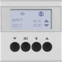
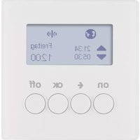

Mærke : HAGER
Model : 85745283
Kategori : Fjernsyn