
75492002 - Luxmeter HAGER - Gratis brugsanvisning og manual
Find enhedens vejledning gratis 75492002 HAGER i PDF-format.


Brugerspørgsmål om 75492002 HAGER
0 spørgsmål om dette apparat. Besvar dem du kender, eller stil dit eget.
Stil et nyt spørgsmål om dette apparat
Download vejledningen til din Luxmeter i PDF-format gratis! Find din vejledning 75492002 - HAGER og tag din elektroniske enhed tilbage i hånden. På denne side er alle dokumenter nødvendige for brugen af din enhed offentliggjort. 75492002 af mærket HAGER.
BRUGSANVISNING 75492002 HAGER
B.
Berker
310 965 02
Operating instructions
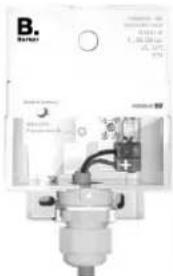
Brightness and temperature sensor surface-mounted 7549 20 02
1. Use
The brightness and temperature sensor is suitable for brightness and temperature measurement for the KNX building management system.
2. Safety
Electrical equipment may only be installed and assembled by a qualified electrician. The national regulations and safety directions must be observed. Please observe the rules and instructions in the ZVEI/ZVEH manual for building management systems to ensure that the bus cables are laid correctly and commissioning of the KNX devices is carried out correctly. Interventions in and modifications to the device will invalidate the warranty.
3. Measurement ranges
Measurement range for brightness measurement
1 to 100 000 lux (tolerance ± 20 % resp. ± 1 Lux)
Measurement range for temperature measurement
-25 °C to + 55 °C (tolerance 5 % resp. ± 1 Grad)
(The larger tolerance applies in each case.)
4. Selecting the installation location
Please note when selecting the installation location
- that the brightness and temperature sensor is exposed to no or to minimal dirt, as a dirty sensor has an adverse effect on the brightness measurement.
- that direct sunlight can interfere with the temperature measurement.
5. Installation of the sensor

Install the brightness and temperature sensor only in a vertical position!
Consequence on non-observance
Moisture and/or dirt can get into the housing! This will result in device malfunctions and will short-circuit the bus cable.

natural_image
Four technical diagrams showing mechanical components and a schematic of a device with labeled dimensions (14 mm x 8 mm)6. Bus connection
- Push the bus cable through the nippel grommet into the terminal compartment.
- Connect the bus terminal to the inserted cable. Pay attention to polarity.
- Press the bus terminal completely onto the contact pins.
natural_image
Exterior view of a mechanical device with no visible text or symbols7. Entry of the physical address
The ETS assigns the physical address, the group addresses; the setting of parameters is also done with the ETS.
Loading of the physical address:
- Press button 1. LED 2 lights up.
- The physical address can be assigned by the ETS.
2

natural_image
Mechanical device with internal components and labeled part 1 (no readable text or symbols)8. Installing and maintaining the cover
Installing the cover
- Place the cover carefully over the installed device.
- Screw on the cover
Maintaining the cover
- Clean the cover from time to time, so that the measured values during brightness measurement are not corrupted by dirt deposits. Use a moist cloth for this.
9. Technical data
Brightness and temperature sensor 7549 20 01
Operating voltage bus voltage
Bus coupling unit integrated
Temperature measuring range -25 °C to +55 °C
Tolerance ± 5 % resp. ± 1 degree
Brightness measuring range 1 to 100 000 Lux
Tolerance ± 20 % min. ± 1 Lux
Power consumption < 150 mW
Degree of protection built-in IP 54
with vertical installation with
attached cover
10. Warranty
We reserve the right to realise technical and formal changes to the product in the interest of technical progress.
Our products are under guarantee within the scope of the statutory provisions. If you have a warranty claim, please contact the point of sale or ship the device postage-free with a description of the fault to our Service Center.
Berker GmbH & Co. KG
Abt. Service-Center
Hubertusstraße 17
D-57482 Wenden-Ottfingen
Phone: 0 23 55 / 90 5-0
Fax: 0 23 55 / 90 5-111


Mærke : HAGER
Model : 75492002
Kategori : Luxmeter