Ecostar WF30 - Opvarmning Braemar - Gratis brugsanvisning og manual
Find enhedens vejledning gratis Ecostar WF30 Braemar i PDF-format.

Brugerspørgsmål om Ecostar WF30 Braemar
0 spørgsmål om dette apparat. Besvar dem du kender, eller stil dit eget.
Stil et nyt spørgsmål om dette apparat
Download vejledningen til din Opvarmning i PDF-format gratis! Find din vejledning Ecostar WF30 - Braemar og tag din elektroniske enhed tilbage i hånden. På denne side er alle dokumenter nødvendige for brugen af din enhed offentliggjort. Ecostar WF30 af mærket Braemar.
BRUGSANVISNING Ecostar WF30 Braemar
It is a condition of your warranty cover that the items in the Schedule below are checked (and action taken as required) every two (2) years after the date of installation by a qualified, licenced technician, and that the Schedule is properly filled out (ie names, signature, date, and action taken). Even after the warranty period expires, please continue to have the product maintained every two years as per the items in the Schedule. This will help to prolong the life of the product and keep it running efficiently. Maintenance Schedule
| Year | 248610 | ||||
| Name of Technician and company(Print) | |||||
| Signature of Technician | |||||
| Date of attendance |
Cabinet and components
| Cabinet | |||||
| Heat exchanger | |||||
| Electrical connections | |||||
| Combustion air inlet louvres |
General installation
| Rear register | |||||
| Flue system, cowl | |||||
| Electrical and gas connections |
Electrical
| Electrical wiring | |||||
| Room fan motor / impeller | |||||
| Thermocouple voltage | |||||
| Overtemp switch |
Gas, burners, ignition
| Main burner and injector | |||||
| Pilot gas rate | |||||
| Pilot burner and injector | |||||
| Pilot ignition / ignition electrode |
Operation
| Start up and run sequence | |||||
| Control operation | |||||
| Complete ignition | |||||
| Gas inlet pressure | kPa | kPa | kPa | kPa | kPa |
| Gas test point pressure High | kPa | kPa | kPa | kPa | kPa |
| Gas test point pressure Low | kPa | kPa | kPa | kPa | kPa |
| Thermostat operation | |||||
| Draught diverter (NOTE 1) |
Action taken key:
√ = Inspected and working correctly no action required
A = Adjustment of part
C = Cleaning of part
R = Replaced part
NOTE 1:
Check operation of flue and draft diverter in accordance with detailed instructions included in AS/NZS 56001.
To owner/user, please note that as explained in your Warranty Card. Installation is not covered by the warranty (for example, electrical and gas connections to the Wall Furnace). However, we still require that you have these things checked, because they can affect the performance (and/or safety) of the heater. This is why we have included them in the Maintenance Schedule. Further, routine maintenance may be required more frequently in non-domestic applications or when operating in adverse environmental situations. It is your obligation to ensure that you comply with these requirements.
It is the policy of Seeley International to introduce continual product improvement. Accordingly, specifications are subject to change without notice. Please consult with your dealer to confirm the specifications of the model selected.
Warranty Service
Australia 1-300-650-644
seeleyinternational.com

SEELEY
INTERNATIONAL

OWNER'S MANUAL
Wall Furnace - WF30/40
natural_image
Exterior view of a tall, beige industrial or laboratory device with a dark band and control panel (no visible text or symbols)(English) (WF30/40)
IMPORTANT MAINTENANCE (AND WARRANTY) INFORMATION
As with any product that has moving parts or is subject to wear and tear, it is VERY IMPORTANT that you maintain your wall furnace and have it regularly serviced. It is a condition of warranty cover for your wall furnace that you comply with all of the maintenance and service requirements set out in this Owner's Manual. Compliance with these requirements will prolong the life of your wall furnace. Further, it is also a condition of warranty cover that each item in the Maintenance Schedule in this Owner's Manual is performed with the frequency indicated, by a qualified, licensed technician, and that the Maintenance Schedule is properly filled out (ie names, signature, date, and action taken) when the item is completed. ANY FAILURE TO CARRY OUT THE REQUIRED MAINTENANCE AND SERVICING REQUIREMENTS, AND ANY FAILURE TO PROPERLY FILL OUT THE MAINTENANCE SCHEDULE, WILL VOID YOUR WARRANTY.
Care Instructions
External surfaces should be cleaned with warm water and detergent with the heater turned off. Do not use abrasive cleaners as scratching of the surface will occur.
Warning
DO NOT: Place articles on or against this appliance.
DO NOT: Use or store flammable materials near this appliance
DO NOT: Spray aerosols in the vicinity of this appliance while it is in operation.
DO NOT: Modify this appliance.
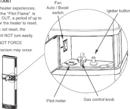
IMPORTANT
If for any reason your heater experiences, a POWER FAILURE, the "Pilot Flame" is TURNED OFF, or GOES OUT, a period of up to 5 minutes is required for the heater to reset. If the heater has not reset, the "Gas control knob" will NOT turn easily. PLEASE DO NOT FORCE Damage to the mechanism may occur.

Braemar
& SEELEY INTERNATIONAL
WF30/40
OPERATING INSTRUCTIONS
Introduction
For satisfactory performance of your Braemar gas wall furnace, please read these instructions carefully. The operation of the heater is controlled by the gas control knob and fan switch located behind the access door on the front cover.
Fan Operation
The fan will start automatically in both AUTO and BOOST positions when the unit is warm enough after the burner is turned on, and stop automatically when the unit has cooled sufficiently after the burner turns off. With AUTO selected the unit will automatically select between "low" and "normal" (and "boost" on 40MJ models) fan speeds based on the heated air temperature - no further user adjustment is necessary. When BOOST is selected the fan will run only on its boost speed. It is recommended that the manual fan switch be set to AUTO for normal operation, or BOOST for rapid heat-up.
Gas Control
To light the heater:
- Turn the gas control knob anti-
clockwise from the "0" position to the
position. - Depress knob fully and hold down
- Press the igniter button located next to the gas control knob 3-4 times.
- Observe the pilot meter to indicate
operation of the pilot. - Wait 20 seconds then release the gas control knob and check the pilot meter stays on.
- Repeat the process if required.
Heat Setting
- Turn gas control knob anti-clockwise to desired heat setting between "1" and "7".
- The heater will automatically adjust the gas flow to maintain the room temperature corresponding to the selected heat setting.
To Increase Heat Setting
- Turn gas control knob anti-clockwise towards "7".
To Decrease Heat Setting
- Turn gas control knob clockwise towards "1".
To Turn Off Main Burner (Pilot-Stand by)
- Turn gas control knob clockwise to a position between the word PILOT & the symbol ★.
(see "Pilot zone" Figure 1 below) It is recommended that the pilot be left in operation during the heating season.
To Turn Off Completely (end of heating season)
- Turn gas control knob clockwise to the "0" position.
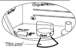
Figure 1: To Turn Off Main Burner (Pilot-Stand by) Heater will now only re-start when control knob is turned to a heat setting of 1 to 7.
SEELEY INTERNATIONAL - OWNER'S MANUAL 2