NevoSwitch 714904 - Kontakt TELEVES - Gratis brugsanvisning og manual
Find enhedens vejledning gratis NevoSwitch 714904 TELEVES i PDF-format.

Brugerspørgsmål om NevoSwitch 714904 TELEVES
0 spørgsmål om dette apparat. Besvar dem du kender, eller stil dit eget.
Stil et nyt spørgsmål om dette apparat
Download vejledningen til din Kontakt i PDF-format gratis! Find din vejledning NevoSwitch 714904 - TELEVES og tag din elektroniske enhed tilbage i hånden. På denne side er alle dokumenter nødvendige for brugen af din enhed offentliggjort. NevoSwitch 714904 af mærket TELEVES.
BRUGSANVISNING NevoSwitch 714904 TELEVES
Televes®

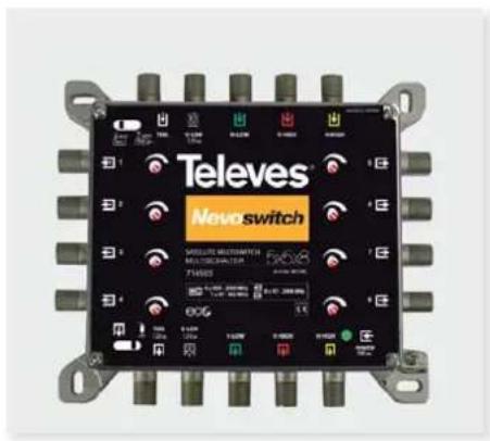
NEVOswitch 5x
ES Hoja Técnica
EN Data Sheet
ES
Nueva gama de conmutadores de 5 entradas y múltiples salidas de usuario, (4...32 según ref.). Dispone de otras 5 salidas de paso que permiten encadenar varios elementos ampliando el número de usuarios fi nales de la instalación (cascada).
Dispone de las siguientes opciones de alimentación:
- A través del jack de Power DC (12V)
- A través de la línea V-Low (12Vbc)
- A través de la entrada o salida de la señal TERR.
- Aplicando entre 12 y 18V en los conectores de salida de usuario.
El paso de alimentación 12 Vdc es hacia las entradas/salidas Ter, V-Low, para la alimentación de preamplifi cadores, antenas BOSS, LNB ú otros elementos encadenados (cascada).
En las referencias QUAD, el multiswitch genera las diferentes combinaciones de tensión y tono hacia la entradas
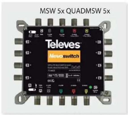
SAT para hacerlo compatible con LNB QUAD.
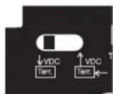
En el caso de la entrada/salida Ter se puede seleccionar el sentido de paso de la corriente mediante el switch 1.
Esta gama incorporá el sistema ECO por el cual el consumo de la instalación se reduce a medida que disminuye el número de usuarios conectados. Incluso el consumo es 0 A, si no se utiliza alimentación local y no hay ningún usuario conectado. En este caso para poder ver la señal Terrestre sería necesario que al menos un usuario estuviera alimentando la instalación.
Para un funcionamiento correcto de la instalación es necesario cargar el paso de las señales con 75 ohmios, para ello se debe confi gurar el switch 2 en la posición en el último modulo de la cascada.
Permite regular el nivel de salida de cada usuario de manera individual (opción no disponible en la gama QUAD).
EN
New range of input/multiple output switches, (from 4 to 32, according to reference). It can be used as a cascade element since it has 5 outputs to connect to other switches and increase the number of users.
It has the following powering options:
- Through the Power DC Jack (12 Vdc)
- Through the V-Low input (12 Vdc).
- Through the TERR input or output.
- Applying 12/18V at any user output.
12V DC passes through the Terr and V-LOW input/output to power pre-amplifiers, BOSS antennas, LNB or other elements (cascade).
The switch can generate the required voltage or voltage + tone (QUAD references) so it's compatible with any QUAD LNB.
The user can select the direction of the current/voltage through the TERR input/output using the Switch No. 1.
This range of products has been designed with the ECO system: as the number of users decreases, the power consumption of the system will decrease as well. When no users are connected and there's no local mains, the consumption will go down to 0A. In this case scenario, to see the DTT signal at least one user must be connected to the system to power it.
Any signal must be balanced to 75 ohms (Switch No. 2) in the last element of the chain for the proper operation of the system.
This range allow to control the output signal level of every user individually. (Not available for the QUAD range).
MSW 5x Splitter

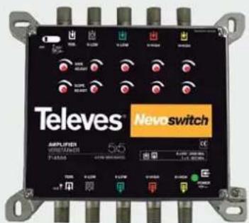
MSW 5x Tap MSW 5x Amplifi er

ES
Estos dispositivos complementan la gama anterior de MSW de forma que se consigue ampliar la instalación a un mayor número de usuarios optimizando la señal que le llegaría a cada uno.
En los amplifi cadores mediante el switch, podemos activar/desactivar el paso de corriente para la alimentación de preamplifi cadores, antenas BOSS,...
EN
This range of products has been designed as a complement to the former MSW range, so any facility can be easily extended to more users, optimizing every output signal.
The voltage/current can be activated/deactivated in the MSW amplifiers to power pre-amplifiers, BOSS antennas, etc.
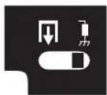
Nota / Note:
Switch 1
Switch 2
NEVOswitch 5x
| Especif. técnicas | Technical specifications | 714501MS54C | 714502MS56C | 714503MS58C | 714504MS512C | 714505MS516C | |||
| Tipo | Type | 5x5x4 5x5x6 | 5x5x8 5x5x12 | 5x5x16 | |||||
| Margen frec. | Frequency range MHz | SAT 950-2400 | |||||||
| TER 47-862 | |||||||||
| Nivel de salida | Max output level dBμV | SAT | EN50083-3 IM35dBc | 109 | |||||
| TER | DIN 45004-B | 105 | |||||||
| Ganancia máxima | Max gain | dB | SAT | - | |||||
| TER | - | ||||||||
| Ecualizador Equaliser | SAT | - | |||||||
| TER | - | ||||||||
| Pérdidas de paso Through losses | SAT | -4 ± 2 - 5 ± 5 - 8 ± 2 | |||||||
| TER - 3 ± 1 | -5 ± 2 | ||||||||
| Pérdidas deriv. | Tap losses (adjustable -12dB) | SAT | Max | -5 ± 5 * | -5 ± 5 * | ||||
| Min | -8 ± 5 * | -10 ± 5 * | |||||||
| TER | Max | -3 ± 5 * | -3 ± 5 * | ||||||
| Aislamiento IN-OUT | Isolation IN-OUT | SAT | >30 | ||||||
| Paso corriente | LNB control signals | mA | LNB/TER | / Input max. | 250 | ||||
| A | Total | 1 | |||||||
| Alimentación | Powering | Vdc | 12 | ||||||
| Paso DC | DC pass | In-Out / Out-In ** | |||||||
| Consumo máx. | Max. consumption | mA | Power Supply 12Vdc (PWR) | 65 ± 5 | 105 ± 10 | 130 ± 10 | |||
| Receiver (12/18V) | 33 *** | ||||||||
| Rango de temperatura | Temperatura Range | °C | -5....+45 °C | ||||||
| Indice de protección | Protection level | IP | IP20 | ||||||
| Peso | Weight | g | 365 | 400 | 765 | 800 | |||
| Dimensiones | Dimensions | mm | 140x120x30 | 140x255x30 | |||||
Televes
| 714506MS524C | 714507MS532C | 714402MS56NCQ | 714403MS58NCQ | 714404MS512NCQ | 714405MS516NCQ | 714901AZ512G | 714902AZ515G | 714903AZ520G | 714904AZ525G | 714905SAV525G | 714509MS530VGQ |
| 5x5x24 5x5x32 5x5x6 QUAD 5x5x8 QUAD 5x5x12 QUAD 5x5x16 QUAD 5x5x5 5x5x5 5x5x5 5x5x5 5x5x5 | |||||||||||
| 950-2400 | |||||||||||
| 47-862 | |||||||||||
| 109 - | 115 | ||||||||||
| 105 -- | |||||||||||
| - | - | 25 ± 4 | |||||||||
| - | - | 27 ± 2 | |||||||||
| - | - | 7 | |||||||||
| - | - | 6 | |||||||||
| -10 ± 5 - 12 ± 5 - 4 ± 2 - 5 ± 5 - 8 ± 4 - 1,5 ± 0,5 - 4 ± 1 | 11 | ||||||||||
| -7 ± 3 | -10 ± 3 | -3 ± 1 | -5 ± 2 | -1,5 ± 0,5 | -4 ± 1 | 17 | |||||
| -5 ± 5 * | -5 ± 5 * | -5 ± 5 | -5 ± 5 | -15 ± 3 | -17 ± 3 - 21 ± 3 - 26 ± 3 | - | - | ||||
| -9 ± 5 * | -12 ± 3 * | -8 ± 5 | -10 ± 5 | ||||||||
| -5 ± 5 * | -8 ± 5 * | -3 ± 5 | -3 ± 5 | -12 ± 1 | -15 ± 1 | -20 ± 1 | -25 ± 1 | - | - | ||
| >30 | >25 | >25 | |||||||||
| 250 | 500 | 250 | 250 | ||||||||
| 1 | - | 1 | |||||||||
| 12 | - | 12 | |||||||||
| In-Out / Out-In ** | In-Out / Out-In | In-Out / Out-In** | - | In-Out / Out-In | |||||||
| 200 ± 15 | 235 ± 25 | 65 ± 5 | 105 ± 10 | 130 ± 10 | - | - | |||||
| 33 *** | - | - | |||||||||
| -5....+45 °C | |||||||||||
| IP20 | |||||||||||
| 1200 | 1600 | 400 | 765 | 800 | 400 | 330 | |||||
| 140x383x30 | 140x510x30 | 140x120x30 | 140x255x30 | 140x120x30 | 140x120x30 | ||||||
NEVOswitch 5x
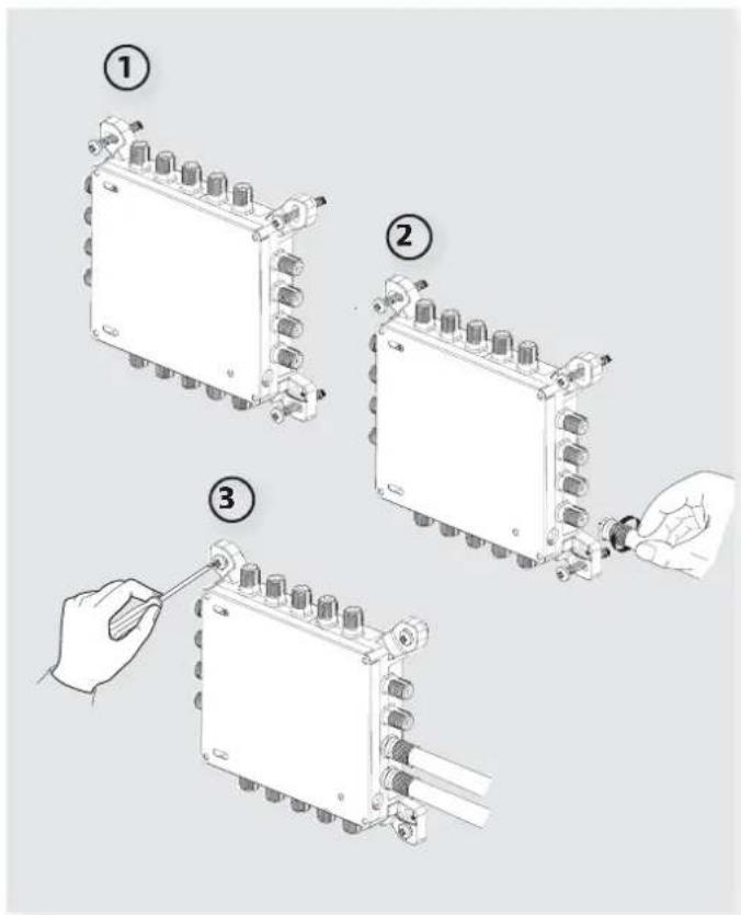
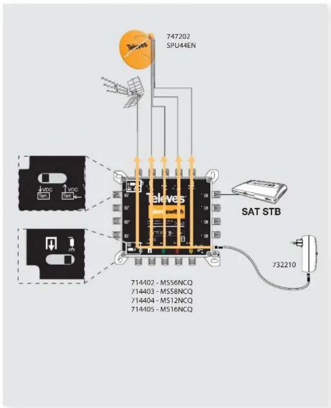
Modo de instalación / Installation mode
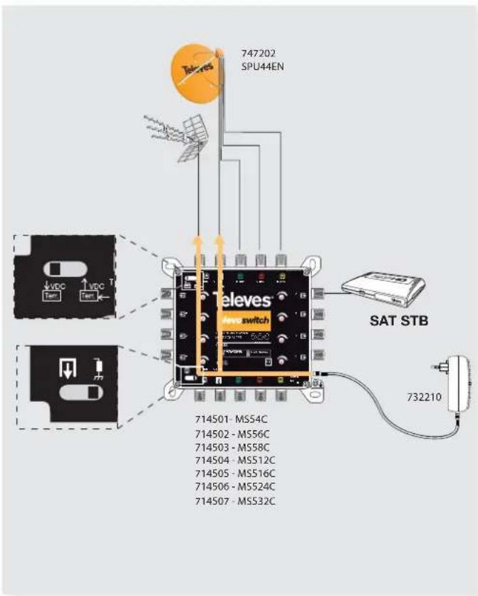
Ejemplo de aplicación 1 / Example of implementation 1
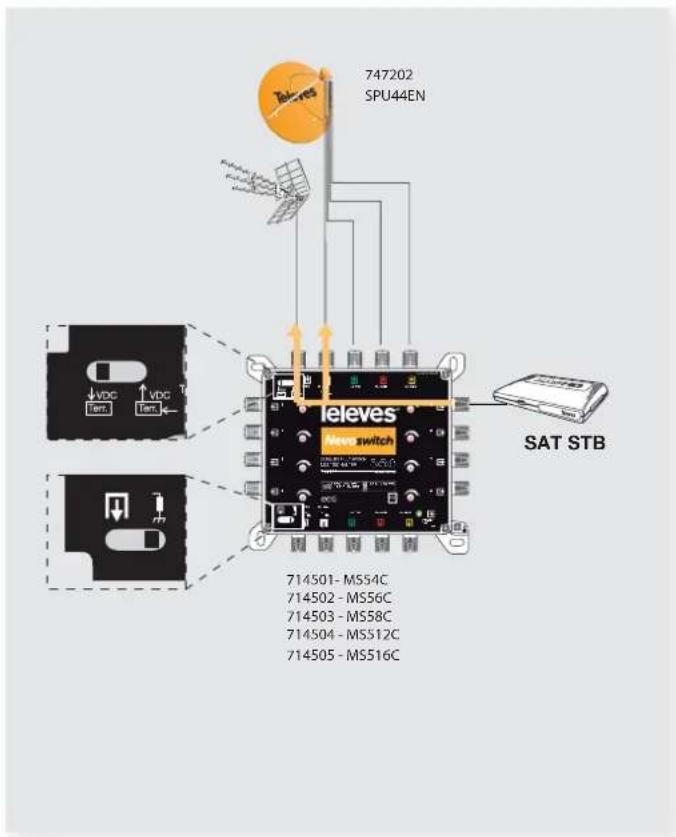
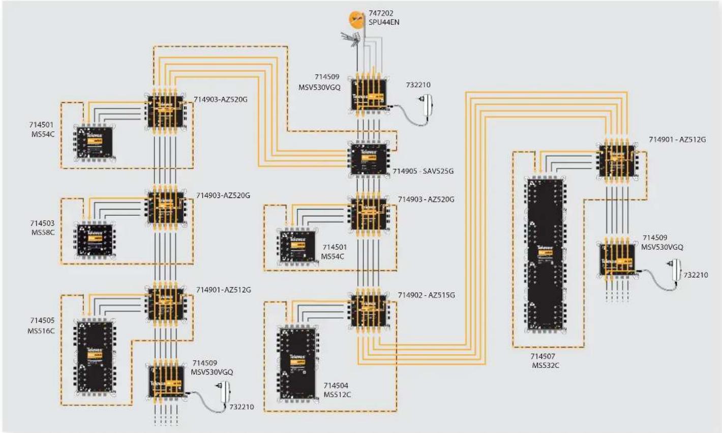
Ejemplo de aplicación 2 / Example of implementation 2
Ejemplo de aplicación 3 /Example of implementation 3
Ejemplo de aplicación 4 / Example of implementation 4
flowchart
graph TD
    A["714501 MS54C"] --> B["714903-AZ520G"]
    C["714503 MS58C"] --> D["714903-AZ520G"]
    E["714505 MS516C"] --> F["714901-AZ512G"]
    G["714509 MSV530VGQ"] --> H["714905 - SAV525G"]
    I["714509 MSV530VGQ"] --> J["714903 - AZ520G"]
    K["714501 MS54C"] --> L["714902 - AZ515G"]
    M["714504 MS512C"] --> N["714907 MSS32C"]
    O["747202 SPU44EN"] --> P["732210"]
    Q["714901 - AZ512G"] --> R["714509 MSV530VGQ"]
    S["714509 MSV530VGQ"] --> T["732210"]
RANGO DE PRODUCTOS PRODUCT RANGE
| RefArt. Nr. | Descripción Description | |
| 714501MS54C | Multiswitch 5x4 5x4 Multiswitch | |
| 714502MS56C | Multiswitch 5x6 5x6 Multiswitch | |
| 714503MS58C | Multiswitch 5x8 5x8 Multiswitch | |
| 714504MS512C | Multiswitch 5x12 5x12 Multiswitch | |
| 714505MS516C | Multiswitch 5x16 5x16 Multiswitch | |
| 714506MS524C | Multiswitch 5x24 5x24 Multiswitch | |
| 714507MS532C | Multiswitch 5x32 5x32 Multiswitch | |
| 714402MS56NCQ | Multiswitch 5x6 QUAD 5x6 Multiswitch QUAD | |
| 714403MS58NCQ | Multiswitch 5x8 QUAD 5x8 Multiswitch QUAD | |
| 714404MS512NCQ | Multiswitch 5x12 QUAD 5x12 Multiswitch QUAD | |
| 714405MS516NCQ | Multiswitch 5x16 QUAD 5x16 Multiswitch QUAD | |
| 714509MS530VGQ | Amplifi cador 5x5 5x5 Amplifi er | |
| 714901AZ512G | Derivador 5x5x5 (12dB) 5x5x5 Tap (12dB) | |
| 714902AZ515G | Derivador 5x5x5 (15dB) 5x5x5 Tap (15dB) | |
| 714903AZ520G | Derivador 5x5x5 (20dB) 5x5x5 Tap (20dB) | |
| 714904AZ525G | Derivador 5x5x5 (25dB) 5x5x5 Tap (25dB) | |
| 714905SAV525G | Repartidor 5 x 5 x 5 5x5x5 Splitter |
ES
Instrucciones de seguridad
Condiciones generales de instalación:
- Antes de manipular o conectar el equipo leer este manual.
- Para reducir el riesgo de fuego o choque eléctrico, no exponer el equipo a la lluvia o a la humedad.
- Deje un espacio libre alrededor del aparato para proporcionar una ventilación adecuada.
- El aparato no debe ser expuesto a caídas o salpicaduras de agua. No situar objetos o recipientes llenos de agua sobre o cerca del aparato si no se tiene la suficiente protección.
- No situar el equipo cerca de fuentes de calor o en ambientes de humedad elevada.
- No situar el equipo donde pueda estar sometido a fuertes vibraciones o sacudidas.
Operación segura del equipo:
- La tensión de alimentación de éste producto se suministra a través de las fuentes de alimentación ref.7321 y 7328 (230V\~ / 12V).
- Si algún líquido u objeto se cayera dentro del equipo, por favor recurra al servicio técnico especializado.
- Para desconectar el equipo de la red, tire del conector, nunca del cable de red.
- No conectar el equipo hasta que todas las demás co- nexiones del equipo hayan sido efectuadas.
Descripción de Simbología de seguridad eléctrica
esgo de choque eléctrico no abrir el equipo.
- Este simbolo indica que el equipo cumple los requerimientos de seguridad para equipos de clase II. - Este simbolo indica que el equipo cumple los requerimientos del marcado CE.
EN
Important safety instructions
General installation conditions:
• Before handling or connecting the equipment, please read this manual.
- In order to reduce the risk of fire or electric shock, do not expose the equipment to rain or moisture.
- Please allow air circulation around the equipment.
- The equipment must not come into contact with water or even be splashed by liquids. Do not place containers with water on or near the equipment if it is not adequately protected.
- Do not place the equipment near sources of heat or in excessively moisture conditions.
- Do not place the equipment where it may be affected by strong vibrations or knocks.
- The powering voltage for this product is provided by the PSUs ref.7321 and 7328 (230V \~ / 12V).
- If any liquid or object falls inside the equipment, please contact a specialized technician.
- To disconnect the equipment from the mains, pull from the connector, and never pull from the cable.
- Do not connect the equipment to the mains until all the other connections have been made.
How to use the equipment safely:
Description of the electrical safety symbols
k of fire or electric
shock, do not open the equipment.

This symbol indi
equipment complies with the safety requirements for class II equipment.

mbol indicates that the
equipment complies with the safety requirements for equipment of marked CE.
DECLARACIÓN DE CONFORMIDAD ▪ DECLARATION OF CONFORMITY DECLARAÇÃO DE CONFORMIDADE ▪ DECLARATION DE CONFORMITE □ DICHIARAZIONE DI CONFORMITÁ ▪ DEKLARACJA ZGODNOŚCI KONFORMITÄTSERKLÄRUNG ▪ ПІЗТОПОИТІКО ΣΥΜΜΟΡΦΩΣΗΣ □ FÖRSÄKRAN OM ÖVERENSSTÄMMELSE ▪ ДЕКЛАРАЦИЯ COOTBETCTВИЯ ▶ www.televes.com
Televes