SCC-C4239P - Accessoire pour barre de son SAMSUNG - Bezplatný návod k obsluze
Najděte návod k zařízení zdarma SCC-C4239P SAMSUNG ve formátu PDF.

Dotazy uživatelů ohledně SCC-C4239P SAMSUNG
0 otázka o tomto zařízení. Odpovězte na ty, které znáte, nebo položte vlastní.
Položte novou otázku o tomto zařízení
Stáhněte si návod pro váš Accessoire pour barre de son ve formátu PDF zdarma! Najděte svůj návod SCC-C4239P - SAMSUNG a vezměte svůj elektronický přístroj zpět do rukou. Na této stránce jsou zveřejněny všechny dokumenty potřebné k používání vašeho zařízení. SCC-C4239P značky SAMSUNG.
NÁVOD K OBSLUZE SCC-C4239P SAMSUNG
Power Zoom Camera User Manual
imagine the possibilities
Thanks you for purchasing this Samsung product.
To receive a more complete service, please visit our website
www.samsungsecurity.com
CAUTION
RISK OF ELECTRIC SHOCK. DO NOT OPEN

CAUTION: TO REDUCE THE RISK OF ELECTRIC SHOCK, DO NOT REMOVE COVER (OR BACK) NO USER SERVICEABLE PARTS INSIDE. REFER SERVICING TO QUALIFIED SERVICE PERSONNEL.
This symbol indicates that dangerous voltage consisting a risk of electric shock is present within this unit.

This symbol indicates that there are important operating and maintenance instructions in the literature accompanying this unit.
WARNING
- To reduce the risk of fire or electric shock, do not expose this appliance to rain or moisture.
- To prevent injury, this apparatus must be securely attached to the floor/wall in accordance with the installation instructions.
WARNING
- Be sure to use only the standard adapter that is specified in the specification sheet.
Using any other adapter could cause fire, electrical shock, or damage to the product. - Incorrectly connecting the power supply or replacing battery may cause explosion, fi re, electric shock, or damage to the product.
- Do not connect multiple cameras to a single adapter. Exceeding the capacity may cause abnormal heat generation or fire.
- Securely plug the power cord into the power receptacle. Insecure connection may cause fi re.
- When installing the camera, fasten it securely and firmly. The fall of camera may cause personal injury.
- Do not place conductive objects (e.g. screwdrivers, coins, metal parts, etc.) or containers filled with water on top of the camera. Doing so may cause personal injury due to fire, electric shock, or falling objects.
- Do not install the unit in humid, dusty, or sooty locations. Doing so may cause
2\_ overview
fi re or electric shock.
- If any unusual smells or smoke come from the unit, stop using the product. In such case, immediately disconnect the power source and contact the service center. Continued use in such a condition may cause fire or electric shock.
- If this product fails to operate normally, contact the nearest service center. Never disassemble or modify this product in any way. (SAMSUNG is not liable for problems caused by unauthorized modifications or attempted repair.)
- When cleaning, do not spray water directly onto parts of the product. Doing so may cause fi re or electric shock.
CAUTION
- Do not drop objects on the product or apply strong blows to it. Keep away from a location subject to excessive vibration or magnetic interference.
- Do not install in a location subject to high temperature (over 50^ C), low temperature (below -10^ C), or high humidity. Doing so may cause fire or electric shock.
- If you want to relocate the already installed product, be sure to turn off the power and then move or reinstall it.
- Remove the power plug from the outlet when there is a lighting storm. Neglecting to do so may cause fire or damage to the product.
- Keep out of direct sunlight and heat radiation sources. It may cause fire.
- Install it in a place with good ventilation.
- Avoid aiming the camera directly towards extremely bright objects such as sun, as this may damage the CCD image sensor.
- Apparatus shall not be exposed to dripping or splashing and no objects filled with liquids, such as vases, shall be placed on the apparatus.
- The Mains plug is used as a disconnect device and shall stay readily operable at any time.
- When using the camera outdoors, moisture may occur inside the camera due to temperature difference between indoors and outdoors. For this reason, it is recommended to install the camera indoors. For outdoor use, use the camera with built-in fan and heater.
IMPORTANT SAFETY INSTRUCTIONS
- Read these instructions.
- Keep these instructions.
-
Heed all warnings.
-
Follow all instructions.
-
Do not use this apparatus near water.
-
Clean only with dry cloth.
-
Do not block any ventilation openings. Install in accordance with the manufacturer's instructions.
-
Do not install near any heat sources such as radiators, heat registers, or other apparatus (including amplifiers) that produce heat.
-
Do not defeat the safety purpose of the polarized or grounding-type plug. A polarized plug has two blades with one wider than the other. A grounding type plug has two blades and a third grounding prong. The wide blade or the third prong is provided for your safety. If the provided plug does not fit into your outlet, consult an electrician for replacement of the obsolete outlet.
-
Protect the power cord from being walked on or pinched particularly at plugs, convenience receptacles, and the point where they exit from the apparatus.
-
Only use attachments/accessories specified by the manufacturer.
-
Use only with the cart, stand, tripod, bracket, or table specified by the manufacturer, or sold with the apparatus. When a cart is used, use caution when moving the cart/ apparatus combination to avoid injury from tip-over.
-
Unplug this apparatus during lightning storms or when unused for long periods of time.
-
Refer all servicing to qualified service personnel. Servicing is required when the apparatus has been damaged in any way, such as powersupply cord or plug is damaged, liquid has been spilled or objects have fallen into the apparatus, the apparatus has been exposed to rain or moisture, does not operate normally, or has been dropped.

natural_image
Symbolic icon of a person climbing a ladder, enclosed in a circle with no text or symbols
Apparatus shall not be exposed to dripping or splashing and no objects filled with liquids, such as vases, shall be placed on the apparatus
4\_ overview
OVERVIEW
2
4 Important Safety Instructions
5 Contents
6 Features
7 What's Included
7 Part Names and Functions
INSTALLATION & CONNECTION
11
11 Preparing Installation
11 Connecting the Cables
SETUP
14
14 Main Menu
15 Profi le
17 Camera Set
26 Intelligent Video
28 Privacy Zone
29 Preset
30 Other Set
31 Communication
31 System Info
32 Language
APPENDIX
33
33 Shortcut Keys
34 Specifications
FEATURES
- With the state-of-the-art digital signal processing technology, full digital image processing and special algorithm of 600-line high resolution implemented.
- High Sensitivity: It implements images of high sensitivity using the up-to-date Super-HAD IT CCD(SCC-C4237P/C4337P)/ExView-HAD PS CCD(SCC-C4239P/C4339P).
- VPS(Virtual Progressive Scan): This is an advanced technology that reproduces a sharp progressive image. This is appropriate to high quality recording and file transfer via the Internet. (SCC-C4239P/C4339P only)
- High performance surveillance camera, equipped with x34 zoom lens and digital zoom IC, enabling monitoring up to 544 times
- WDR extends the contrast range as it takes a picture of each of dark and bright areas before compositing the two, which is useful if you take a picture of windows inside a building. Namely, it improves the picture quality of the outdoor scenery as well as indoor.(SCC-C4239P/C4339P only)
- Low Illumination: It uses the digital signal technologies such as low illumination and Day/Night functions that make your camera identify objects even in the worst environment.
- XDR (eXtended Dynamic Range): Actively controls the gamma compensation in the way it operates the ambient luminance contrast in a certain pixel unit to determine the optimal visibility.
- Digital Power Synchronization: The full digital Line Lock function directly adjusts the vertical camera synchronization to enhance the operationability and reliability of this camera.(SCC-C4337P/C4339P only)
- DAY/NIGHT: This function can make the IR Cut fi Itering function inactive under the illumination below the normal value.
- White Balance to control the brightness to the illumination
- Superior Backlight Adjustment: When an object has a bright illumination or sunlight behind it, this camera automatically improves the shaded object picture quality.
• Auto Focus to automatically adjust the focus to the subject movement - Privacy zone to hide a specific area for personal privacy.
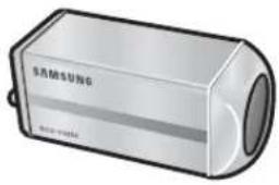
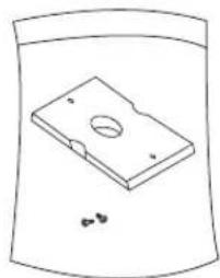
WHAT'S INCLUDED
Please check if your camera and accessories are all included in the product package.
text_image
S.光标本U406 ISO-2017-035Camera
natural_image
Simple line drawing of a rectangular electronic component with a circular hole and small dots, enclosed in a curved container (no text or symbols)Camera Holder (Mount Adaptor) 2 Screws

User's Manual
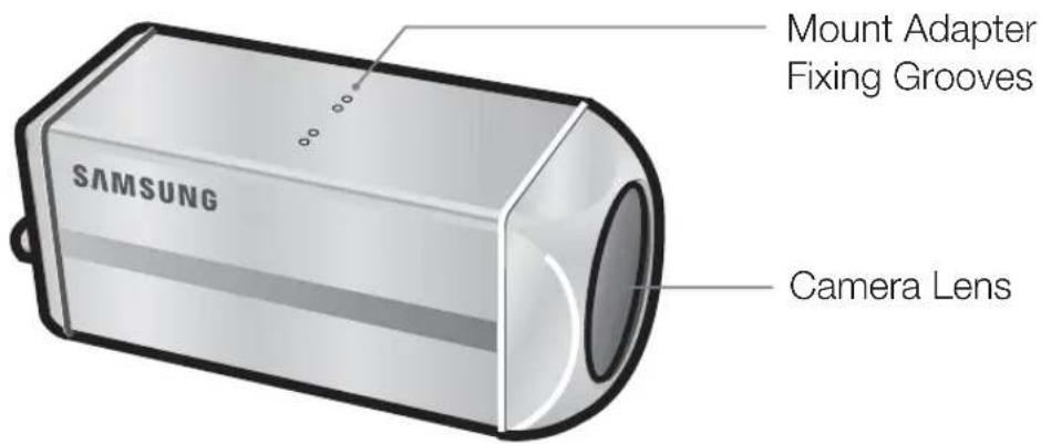
PART NAMES AND FUNCTIONS
SIDE VIEW
text_image
Mount Adapter Fixing Grooves SAMSUNG Camera Lens
- Wipe out a dirty surface of the lens softly with a lens tissue or cloth to which you have applied ethanol.
Rear Panel
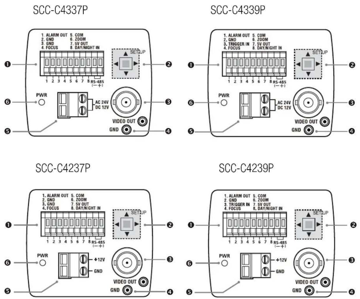
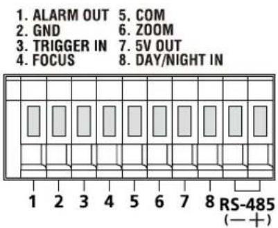
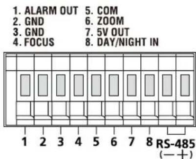
① Input/Output Connector
This connector has input and output ports for RS-485 control signals, DAY/NIGHT switching, and alarm output signals.
text_image
1. ALARM OUT 5. COM 2. GND 6. ZOOM 3. TRIGGER IN 7. 5V OUT 4. FOCUS 8. DAY/NIGHT IN RS-485 (—+)SCC-C4239P/C4339P
text_image
1. ALARM OUT 5. COM 2. GND 6. ZOOM 3. GND 7. 5V OUT 4. FOCUS 8. DAY/NIGHT IN RS-485 (— +)SCC-C4237P/C4337P
1. ALARM OUT
Alarm out jack for motion detection. (Open Collector, On Gnd)
2. GND
Grounding jack.
3. TRIGGER IN (SCC-C4239P/C4339P)
Displays the current still image when it receives the Trigger signal. (Normal Open Type)
4.5.6 FOCUS, COM, ZOOM
This port is used for ZOOM/FOCUS, MENU CONTROL, HOME RETURN, and ONEAF by using an external controller.
Depending on the input condition, 4 modes, A, B, C, and D are available. (SPECIAL - CTRL TYPE)
(Operation Voltage Range : +3V\~+13V, -3V\~-13V)
1) When the voltage is supplied to either ZOOM or FOCUS port
| Function *1 Code | Tele(Up) | Wide(Down) | Near(Left) | Far(Right) |
| ZOOM Port FOCUS Port | ||||
| A -6V +6V -6V +6V | ||||
| B -6V +6V +6V -6V | ||||
| C +6V -6V -6V +6V | ||||
| D | +6V -6V +6V -6V | |||
*1: During MENU OFF, controls ZOOM/FOCUS and during MENU ON, changes the direction, Up/Down/Left/Right SETUP switch.
2) When the voltage is supplied to both ports
| Function Code | ENTER/AF *2 HOME RETURN *3 | |||
| ZOOM Port | FOCUS Port | ZOOM Port | FOCUS Port | |
| A -6V -6V +6V +6V | ||||
| B -6V +6V +6V -6V | ||||
| C +6V -6V -6V +6V | ||||
| D | +6V +6V -6V -6V | |||
* 2 : For short voltage supply during MENU OFF, executes ONEAF and for more than 2 second
* 3 : For more than 2 second long voltage supply, moves to the PRESET 0(HOME) position.
7.5V OUT
Power supply jack for RS-485 JIG. Use within typical DC +5V 100mA.
8. DAY/NIGHT IN
This is a function to receive the external DAY/NIGHT signal from the sensor(option) and convert the signal into BW.
9. RS-485 DATA-
Jack for connection to RS-485 DATA- signal line.
10. RS-485 DATA+
Jack for connection to RS-485 DATA+ signal line.
② SETUP Switch
This switch is used to set the function or property. When this switch is pressed for at least 2 seconds, the MAIN MENU appears.
◀▶ (Left/Right) : By pressing this switch left or right, you can move left or right on the menu or change the displayed value.
▲▼ (Up/Down): By pressing this switch up or down, you can move up or down on the menu.
☐ : When you press this switch in the menu, the selected function is confirmed. To enter a submenu, press this button.
③ Video OUT Port
This is connected to the Video Input Port of the monitor and it outputs the Video signals.
④ GND
This is a grounding port.
⑤ Power Connection Port
This is connected to the Power cable.
⑥ Power Display LED
When the power is normally connected, the red LED lights.
PREPARING INSTALLATION
- To install and use the camera, first prepare the following cables.
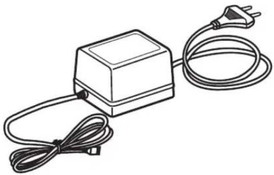
① POWER ADAPTER CABLE (SOLD SEPARATELY)
The requirements for the power adapter, which connects to the camera's POWER IN terminal, are as follows:
- SCC-C4237P/C4239P : DC 12V 600mA
- SCC-C4337P/C4339P: AC 24V 300mA
DC 12V 600mA
natural_image
Line drawing of a rectangular electronic device with a coiled cable and power plug (no text or symbols)② VIDEO CABLE(SOLD SEPARATELY)
Use a BNC cable, such as the one shown below, to connect the camera's VIDEO OUT to the monitor.
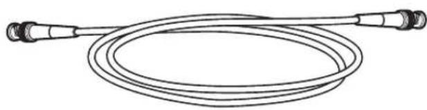
natural_image
Line drawing of a coiled cable with two connectors (no text or symbols)INSTALLATION
- Connect one end of the BNC cable(not included) to the VIDEO OUT.
- Connect the other end of the BNC cable (not included) to the VIDEO IN of the monitor.
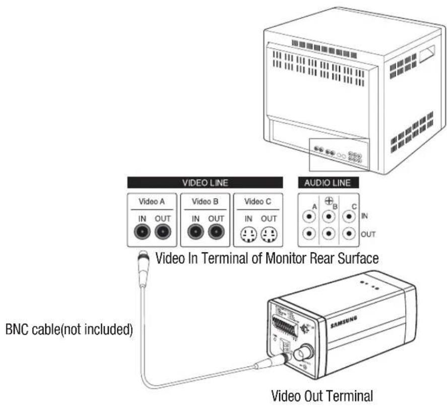
text_image
VIDEO LINE AUDIO LINE Video A IN OUT Video B IN OUT Video C IN OUT A B C IN OUT Video In Terminal of Monitor Rear Surface BNC cable(not included) SAMSUNG Video Out Terminal- Plug in the power adapter(not included). Use a "minus" screwdriver to connect one part of the power adapter, which consists of two lines, to the POWER terminal of the camera as follows :
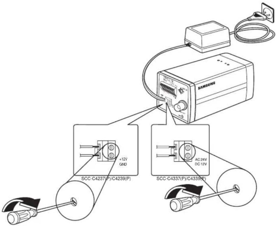
text_image
SAMSUNG +12V GND SCC-C4237(P)/C4239(P) AC 24V DC 12V12_ installation & connection
- Determine the type of power supply and set the POWER SELECTION switch accordingly. Next, plug the power adapter into a wall outlet.
- If the camera operates normally, the following screen will be displayed for 5 seconds and then disappears.
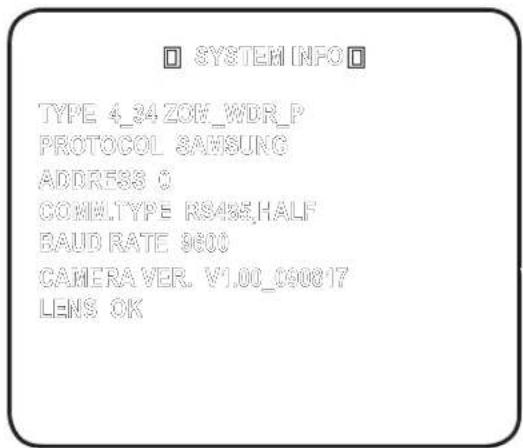
text_image
SYSTEM INFO TYPE 4_34 ZOK_WDR_P PROTOCOL SAMSUNG ADDRESS 0 COMMULTYPE RS485.HALF BAUD RATE 9600 CAMERAVER. V1.00_090817 LENS OK-
The requirements for RS485 control is as follows :
-
Signaling Speed: 9600 bps
- Data Bit : 8 bits
- Stop Bit : 1 bit
- Parity Bit : none
Using OSD icons
- ◀▶: If these icons appear in the left and right corner of a menu item, you can use them move to the previous or next menu.
- (EXIT): Exits the menu setup screen.
Before exiting the setup screen, select
to save your settings to the whole menus, or to cancel them. - (RET): Saves your settings and returns to the previous screen.
• (HOME): Returns to the main menu. - (SAVE): Use this icon if you want to save your settings after you specified the mask area and privacy area, etc.
Once you saved your settings, the changes remain intact even if you select
- (DEL): Use this icon if you want to delete a mask, or privacy area, etc. Once you deleted your settings, the deletions remain valid even if you select
on exit. - ←: This icon appears in the right of a menu containing sub menu items.
MAIN MENU
This is the first screen you ever see when you turn on the camera where you can set the camera environment to your needs.
- PROFILE
Select a mode appr--opriate to the camera installation environment.
- CAMERA SET
You can configure the camera settings.
• INTELLIGENCE
Offers motion detection and tracking functions.
- PRIVACY ZONE
You can configure the privacy settings.
- PRESET
You can set the PRESET POSITION.
- OTHER SET
You can reset the camera, or adjust the OSD color to your preference.
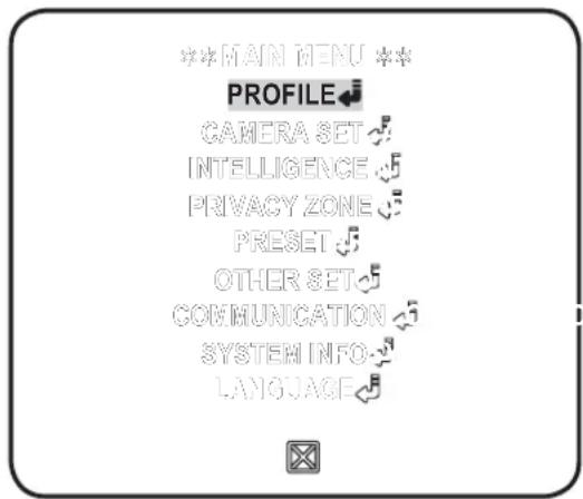
text_image
***MAIN MENU PROFILE CAMERA SET INTELLIGENCE PRIVACY ZONE PRESET OTHER SET COMMUNICATION SYSTEM INFO LANGUAGE• COMMUNICATION
Conf i gures the settings pertaining to RS-485 communication.
- SYSTEM INFO
Shows the system information such as the camera version or communication settings.
- LANGUAGE
Select a preferred one from the supported languages.
PROFILE
You can select one from the pre-determined confi gurations as appropriate to your specifi c camera installation environment.
Your selection on each item in PROFILE will affect all other settings of the camera.
- STANDARD
Automatically optimizes the camera settings to the normal environment.
• ITS
This setting enables you to analyze the traffic situation and take the traffic information at a glance.
- BACKLIGHT
This setting enables you to view a sharp background and object even in a severe backlight scene.
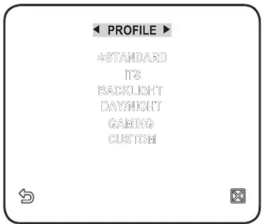
text_image
PROFILE *STANDARD ITS BACKLIGHT DAYNIGHT GAMING CUSTOM- DAY/NIGHT
Automatically optimizes the camera settings to the day and night scene.
• GAMING
This automatically configures the settings so that you can work in a stable illumination condition as indoors.
- CUSTOM
Your change to any of the PROFILE settings will switch the display to CUSTOM.
| CAMERA SETUP MENU | STANDARD ITS BACKLIGHT DAY/NIGHT GAMING | |||||
| Parent Menu | Sub-menus | |||||
| VPS OFF | ON OFF OFF OFF | |||||
| IRIS | ALC ALC ALC ALC ALC | |||||
| ALC - | - | - | - | - | ||
| LEVEL 0 | 0 | 0 | 0 | 0 | ||
| BACKLIGHT OFF OFF WDR OFF OFF | ||||||
| WDR - | - | - | - | - | ||
| WEIGHT | Custom Setting | Custom Setting | MEDIUM | Custom Setting | Custom Setting | |
| WDR LEVEL | Custom Setting | Custom Setting | 0 | Custom Setting | Custom Setting | |
| WHITE BAL | Custom Setting Custom Setting Custom Setting Custom Setting Custom Setting | Setting | ||||
| MOTION | (F.FAST)--- | (F.FAST)--- | NORM | (F.FAST)--- | SLOW | |
| DNR | MEDIUM | MEDIUM | MEDIUM | MEDIUM | MEDIUM | |
| SHUTTER | OFF OFF OFF OFF | |||||
| SENSE UP | AUTO X4 | AUTO X2 | AUTO X4 | AUTO X4 | AUTO X4 | |
| XDR | MEDIUM | MEDIUM | MEDIUM | MEDIUM | MEDIUM | |
| DAY/NIGHT | AUTO | AUTO | DAY | AUTO | DAY | |
| NIGHT | - | - | - | - | - | |
| BURST OFF ON OFF OFF OFF | ||||||
| EXT | - | - | - | - | - | |
| BURST | - | - | - | - | - | |
| WHITE BAL | DAY DAY/NIGHT DAY DAY/NIGHT DAY | |||||
| DAY | - | - | - | - | - | |
| MODE | ATW2 | ATW1 | ATW1 | ATW1 | ATW1 | |
| RED 0 | 0 | 0 | 0 | 0 | ||
| BLUE 0 | 0 | 0 | 0 | 0 | ||
| NIGHT | - | - | - | - | - | |
| BRIGHTNESS | - | MEDIUM | - | MEDIUM | - | |
| MODE | OFF | ATW2 | OFF | ATW2 | OFF | |
| RED | - | 0 | - | 0 | - | |
| BLUE | - | 0 | - | 0 | - | |
| DETAIL | 2 | 2 | 2 | 2 | 2 | |
You can configure the general settings of the camera module.
- Select
- . The Camera Setup menu appears. - Change the settings as necessary, or select an item to check.
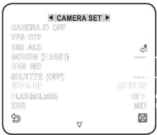
text_image
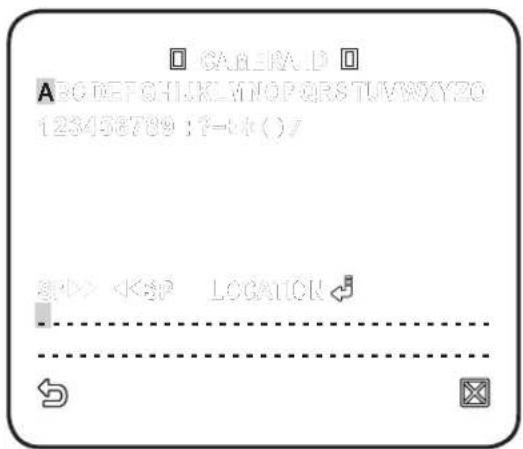
CAMERA SET CAMERA ID OFF VPS OFF IRIS ALC MOTION (F.FAST) DNR MID SHUTTER (OFF) SENS-UP AUTO M FLICKERLESS OFF XDR MIDCAMERA ID
Provide the ID and location for a camera that displays on the screen.
- Select
- . - Use ▲▼◀▶ to select a desired character, then press [ENTER].
In the lower input box of the screen, the selected character will be entered.
■ You can enter up to 54 characters including alphabets, numbers and special characters.
- LOCATION : Specify the display position of the camera ID.